110 VOLKSWAGEN TRANSPORTER 2011 Owners Manual
[x] Cancel search | Manufacturer: VOLKSWAGEN, Model Year: 2011, Model line: TRANSPORTER, Model: VOLKSWAGEN TRANSPORTER 2011Pages: 486, PDF Size: 69.28 MB
Page 18 of 486
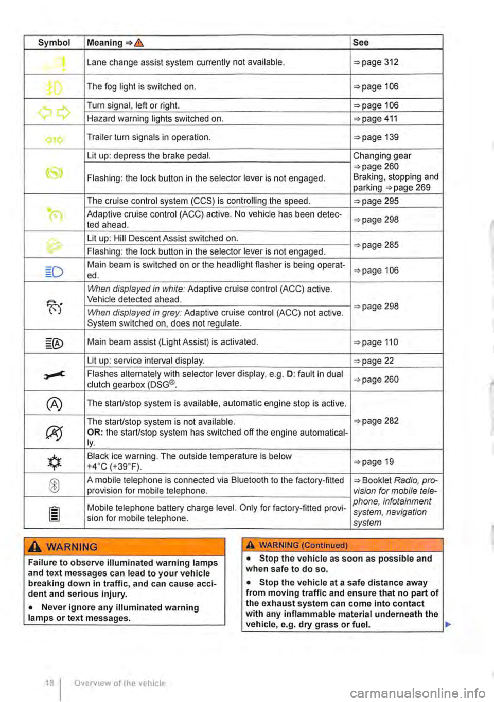
Symbol Meaning=>& See
Lane change assist system currently not available. =>page 312 .
The fog light is switched on. =>page 106
.......,,...., Turn signal, left or right. =>page 106 r., Hazard warning lights switched on. =>page 411
Trailer turn signals in operation. =>page 139
Lit up: depress the brake pedal. Changing gear
CS» =>page 260 Flashing: the lock button in the selector lever is not engaged. Braking, stopping and parking =>page 269
The cruise control system (CCS) is controlling the speed. =>page 295
(") Adaptive cruise control (ACC) active. No vehicle has been detec-ted ahead. =>page 298
th. Lit up: Hill Descent Assist switched on. =>page 285 Flashing: the lock button in the selector lever is not engaged.
Main beam is switched on or the headlight flasher is being opera!-=>page 106 ed.
When displayed in white: Adaptive cruise control (ACC) active.
B'
Vehicle detected ahead.
When displayed in grey: Adaptive cruise control (ACC) not active. =>page 298
System switched on, does not regulate.
Main beam assist (Light Assist) is activated. =>page 110
Lit up: service interval display. =>page 22
,....c. Flashes alternately with selector lever display, e.g. 0: fault in dual clutch gearbox (DSG®. =>page 260
(A) The starUstop system is available, automatic engine stop is active.
The starUstop system is not available. =>page 282
(J9 OR: the starUstop system has switched off the engine automatical-ly.
*
Black ice warning. The outside temperature is below =>page 19 +4·c (+39.F).
® A mobile telephone is connected via Bluetooth to the factory-fitted => Booklet Radio, pro-provision for mobile telephone. vision for mobile tele-
Mobile telephone battery charge level. Only for factory-fitted provi-phone, infotainment system, navigation sion for mobile telephone. system
A WARNING A WARNING (Continued)
Failure to observe illuminated warning lamps and text messages can lead to your vehicle breaking down in traffic, and can cause acci-dent and serious injury.
• Never ignore any illuminated warning lamps or text messages.
Overv1ew of the vehicle
• Stop the vehicle as soon as possible and when safe to do so.
• Stop the vehicle at a safe distance away from moving traffic and ensure that no part of the exhaust system can come Into contact with any inflammable material underneath the vehicle, e.g. dry grass or fuel. ll>
Page 29 of 486
Possible displays
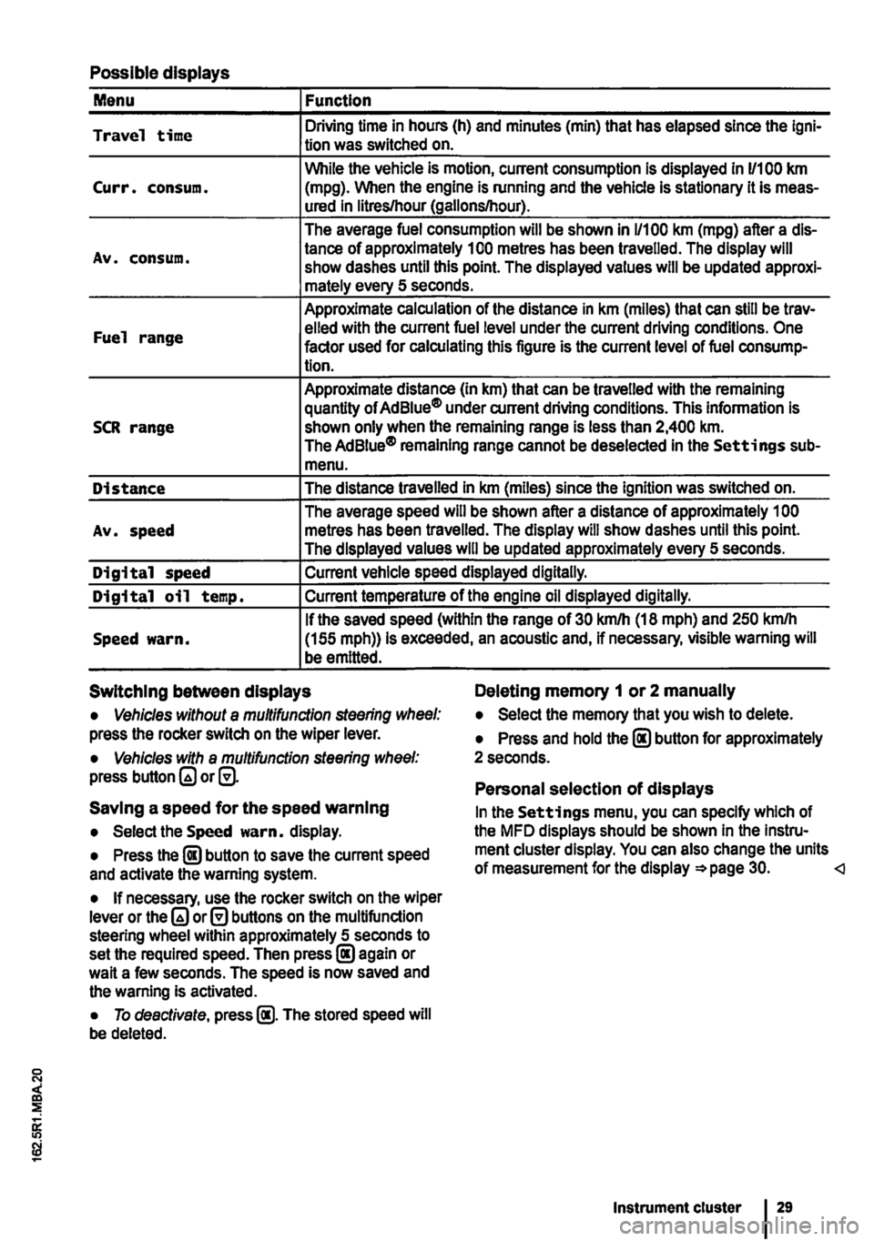
Menu Function
Travel time Driving time in hours (h) and minutes (min) that has elapsed since the lgni-tion was switched on.
While the vehicle is motion, current consumption is displayed in 11100 km Curr. consum. (mpg). When the engine is running and the vehicle is stationary it is meas-ured in litres/hour (gallons/hour).
The average fuel consumption will be shown in 1/100 km (mpg) after a dis-
Av. consum. tance of approximately 100 metres has been travelled. The display will show dashes until this point. The displayed values will be updated approxi-mately every 5 seconds.
Approximate calculation of the distance in km (miles) that can still be trav-
Fuel range elled with the current fuel level under the current driving conditions. One factor used for calculating this figure is the current level of fuel consump-tion.
Approximate distance (In km) that can be travelled with the remaining quantity of Ad Blue® under current driving conditions. This information is SCR range shown only when the remaining range is less than 2,400 km. The AdBiue® remaining range cannot be deselected in the Settings sub-menu.
Distance The distance travelled in km (miles) since the ignition was switched on.
The average speed will be shown after a distance of approximately 1 00 Av. speed metres has been travelled. The display will show dashes until this point. The displayed values will be updated approximately every 5 seconds.
Digital speed Current vehicle speed displayed digitally.
Digital oil temp. Current temperature of the engine oil displayed digitally.
If the saved speed (within the range of 30 km/h (18 mph) and 250 kmlh Speed warn. (155 mph)) is exceeded, an acoustic and, if necessary, visible warning will be emitted.
Switching between displays Deleting memory 1 or 2 manually
• Vehicles without a multifunction steering wheel: press the rocker switch on the wiper lever.
• Vehicles with a multifunction steering wheel: press button or@.
Saving a speed for the speed warning
• Select the Speed warn. display.
• Press the @ button to save the current speed and activate the warning system.
• If necessary, use the rocker switch on the wiper lever or the or@ buttons on the multifunction steering wheel within approximately 5 seconds to set the required speed. Then press@ again or wait a few seconds. The speed is now saved and the warning Is activated.
• To deactivate, press @. The stored speed will be deleted.
• Select the memory that you wish to delete.
• Press and hold the @ button for approximately 2 seconds.
Personal selection of displays
In the Settings menu, you can specify which of the MFD displays should be shown In the Instru-ment cluster display. You can also change the units of measurement for the display =*page 30.
Page 80 of 486
A WARNING (Continued)
• If the belt webbing or any other part of the seat belt becomes damaged, the seat belt may tear during an accident or sudden brak-Ing manoeuvre.
• Damaged seat belts must be replaced Im-mediately with new seat belts approved by Volkswagen Commercial Vehicles for your ve-hicle type. Seat belts subjected to stress and stretched d urlng an accident must be re-placed by a qualified workshop. Renewal may
Warning lamp
sn-0110
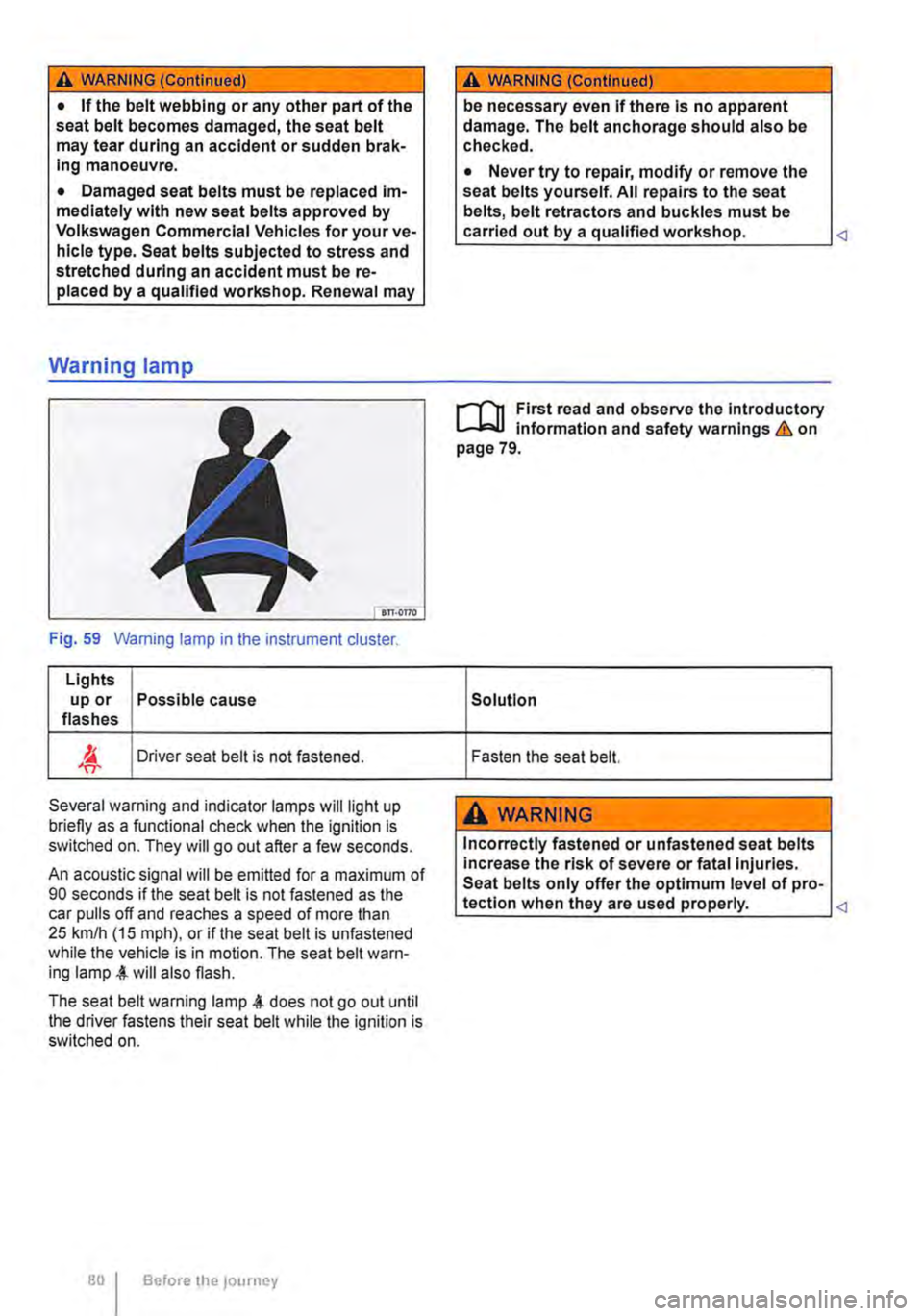
Fig. 59 Warning lamp in the instrument cluster.
Lights up or Possible cause flashes
'IT-Driver seat belt is not fastened.
Several warning and indicator lamps will light up briefly as a functional check when the ignition is switched on. They will go out after a few seconds.
An acoustic signal will be emitted for a maximum of 90 seconds if the seat belt is not fastened as the car pulls off and reaches a speed of more than 25 km/h (15 m ph), or if the seat belt is unfastened while the vehicle is in motion. The seat belt warn-ing will also flash.
The seat belt warning lamp does not go out until the driver fastens their seat belt while the ignition is switched on.
Before the journey
A WARNING (Continued)
be necessary even If there Is no apparent damage. The belt anchorage should also be checked.
• Never try to repair, modify or remove the seat belts yourself. All repairs to the seat belts, belt retractors and buckles must be carried out by a qualified workshop.
r-Y'n First read and observe the Introductory information and safety warnings & on page 79.
Solution
Fasten the seat belt.
A WARNING
Incorrectly fastened or unfastened seat belts Increase the risk of severe or fatal Injuries. Seat belts only offer the optimum level of pro-tection when they are used properly.
Page 101 of 486
Installing child seats with ISOFIX ISOFIX/i-
Size
The location of the ISO FIX anchor points is shown either by a symbol or by a label marked "ISOFIX" 79.
• Observe the warnings 97, Basic infor-mation on fitting and using child seats.
• Push the attachment arms on the child seat into the ISOFIX anchor points 79 as shown by the arrows. The child seat must click and audibly securely into place.
• Pull on both sides of the child seat to check whether the seat has clicked properly into place.
• If the child seat is fitted with a support foot, the foot must sit firmly on the floor of the vehicle.
Using insert guides
If the child seat anchor points are not directly ac-cessible, insert guides make fitting and removing the child seat easier. First attach the insert guides to the anchor points. Then secure the child seat as per the installation guide.
CD
Avoid damage to the upholstery and seat cush-ions caused by the Insert guides.
• Always pull the insert guides off the anchor points before folding the rear seat forward, or when removing the child seat.
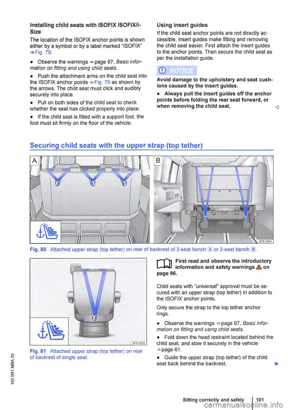
Fig. 80 Attached upper strap (top tether) on rear of backrest of 3-seat or 2-seat bench [ID.
87E-0783
Fig. 81 Attached upper strap (top tether) on rear of backrest of single seat.
r-1'11 First read and observe the Introductory L-lcJ.I Information and safety warnings & on page 96.
Child seats with "universal" approval must be se-cured with an upper strap (top tether) in addition to the ISOFIX anchor points.
Only secure the strap to the top tether anchor rings.
• Observe the warnings 97, Basic infor-mation on fitting and using child seats.
• Fold down the head restraint located behind the child seat, and stow it securely in the vehicle 61.
• Guide the upper strap (top tether) of the child seat back behind the backrest. )I>
Sitting correctly and safely 1101
Page 106 of 486
Lights and vision
Lights
0::0 Introduction
This chapter contains information on the following subjects:
Indicator lamps . . . . . . . . . . . . . . . . . 106
Turn signal and main beam lever . . 107 Switching lights on and off . . . . . . . . 108
Lights and vision -functions . . . . . . . . . . . . . . 109
Main beam assist ....................... 110
Masking or switching over headlights for driving abroad . . . . . . . . . 111
Coming Home and Leaving Home functions (orientation lighting).............. 112
Headlight range control, instrument and switch lighting . . . . . 113 Interior and reading lights . . . . . . . . . 114
Observe any country-specific regulations when us-ing vehicle lighting.
The driver is responsible for the correct headlight position and the correct headlight setting.
Additional information and warnings:
• Exterior views ""page 5
• Volkswagen information system =oo page 24
• Changing bulbs =oo page 432
Indicator lamps
A WARNING
Accidents and serious injuries can occur if roads are not sufficiently Illuminated and oth-er road users have difficulty seeing the vehi-cle, or cannot see it at all.
• Always switch the dipped beam head-lights on if it is dark, raining or visibility is poor.
A WARNING
Setting headlights too high, and the incorrect use of the main beam, could distract and daz-zle other road users. This can lead to acci-dents and serious injuries.
• Always ensure that the headlights are ad-j usted correctly.
• Never use the main beam or the headlight flasher if other road users could be dazzled.
[Qj First read and observe the introductory information and safety warnings & on page 106.
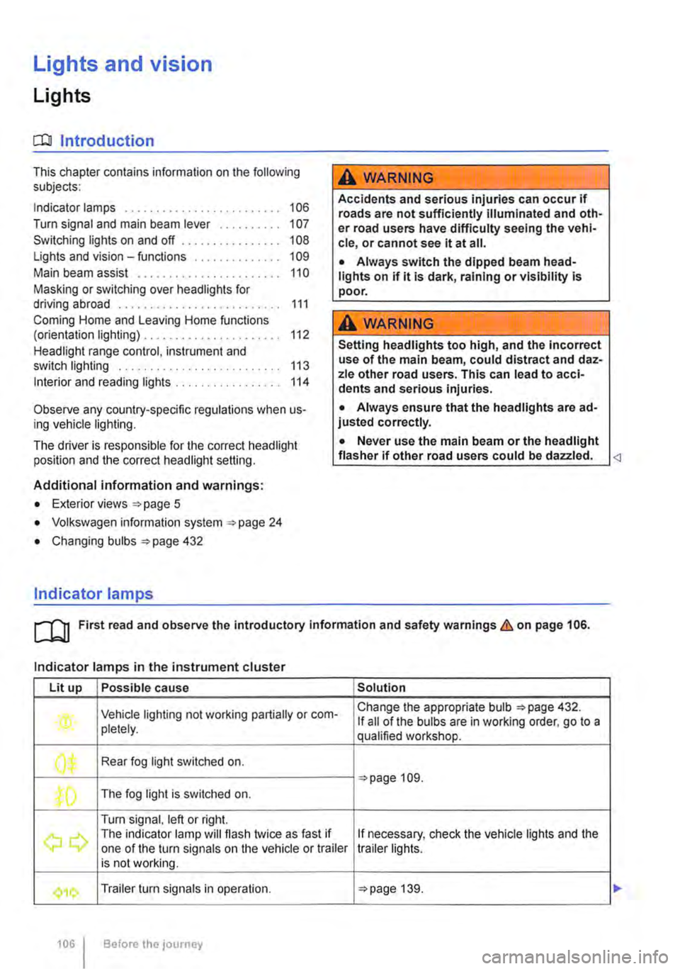
Indicator lamps in the instrument cluster
Lit up Possible cause Solution
Vehicle lighting not working partially or corn-Change the appropriate bulb 432. If all of the bulbs are in working order. go to a pletely. qualified workshop.
' Rear fog light switched on. J", =oopage 109.
,( The fog light is switched on.
Turn signal, left or right.
r The indicator lamp will flash twice as fast if If necessary, check the vehicle lights and the one of the turn signals on the vehicle or trailer trailer lights. is not working.
'111 Trailer turn signals in operation. 139.
106 Before the journey
Page 107 of 486
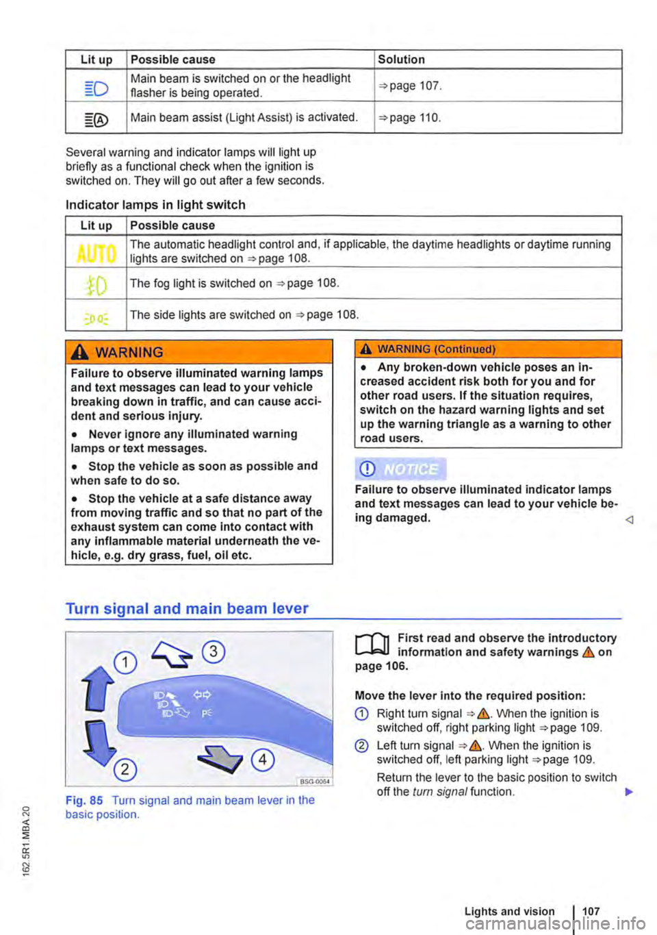
Lit up Possible cause Solution
Main beam is switched on or the headlight 107. flasher is being operated.
Main beam assist (light Assist) is activated. 110.
Several warning and indicator lamps will light up briefly as a funclional check when the ignition is switched on. They will go out after a few seconds.
Indicator lamps in light switch
Lit up Possible cause
The automatic headlight control and, if applicable, the daytime headlights or daytime running Jl lights are switched on 108 .
.fD The fog light is switched on 108.
I) I The side lights are switched on 108.
A WARNING
Failure to observe illuminated warning lamps and text messages can lead to your vehicle breaking down in traffic, and can cause acci-dent and serious injury.
• Never Ignore any illuminated warning lamps or text messages.
• Stop the vehicle as soon as possible and when safe to do so.
• Stop the vehicle at a safe distance away from moving traffic and so that no part of the exhaust system can come into contact with any inflammable material underneath the ve-hicle, e.g. dry grass, fuel, oil etc.
Turn signal and main beam lever
A WARNING (Continued)
• Any broken-down vehicle poses an In-creased accident risk both for you and for other road users. If the situation requires, switch on the hazard warning lights and set up the warning triangle as a warning to other road users.
CD
Failure to observe illuminated indicator lamps and text messages can lead to your vehicle be-ing damaged.
...--r'l1 First read and observe the introductory l.-Jo:JJ information and safety warnings & on page 106.
Move the lever into the required position:
CD Right tu m signal &. VVhen the ignition is switched off, right parking light 109.
@ Left turn signal &. VVhen the ignition is switched off, left parking light 109.
Return the lever to the basic position to switch
<]
Fig. 85 Turn signal and main beam lever in the basic position.
off the turn signal function. 1>
Lights and vision 1107
Page 109 of 486
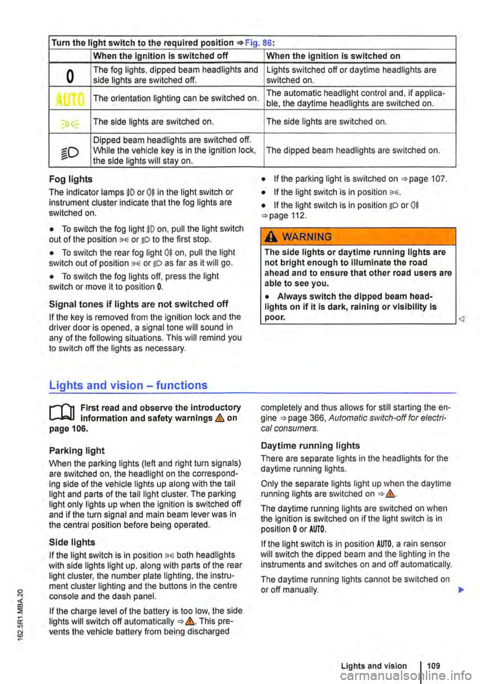
Turn the light switch to the required position 86:
When the Ignition Is switched off
0 The fog lights, dipped beam headlights and side lights are switched off.
,. The orientation lighting can be switched on.
) , The side lights are switched on.
Dipped beam headlights are switched off.
"'D While the vehicle key is in lhe ignition lock, the side lights will stay on.
Fog lights
The indicator lamps or 0$ in the light switch or Instrument cluster indicate that the fog lights are switched on.
• To switch the fog light on, pull the light switch out of the position "" or tD to the first stop.
• To switch the rear fog light 0$ on, pull the light switch out of position ,.,, or gD as far as it will go.
• To switch the fog lights off, press the light switch or move it to position 0.
Signal tones if lights are not switched off
If the key is removed from the ignition lock and the driver door is opened, a signal tone will sound in any of the following situations. This will remind you to switch off the lights as necessary.
Lights and vision -functions
1""1'11 First read and observe the introductory L-lo:.U Information and safety warnings & on page 106.
Parking light
When the parking lights (left and right turn signals) are switched on, the headlight on the correspond-ing side of the vehicle lights up along with the tail light and parts of the tail light cluster. The parking light only lights up when the Ignition is switched off and if the turn signal and main beam lever was in the central position before being operated.
Side lights
If the light switch is in position ;.o; both headlights with side lights light up, along with parts of the rear light cluster, the number plate lighting, the instru-ment cluster lighting and the buttons in the centre console and the dash panel.
If the charge level of the battery is too low, the side lights will switch off automatically &. This pre-vents the vehicle battery from being discharged
When the Ignition Is switched on
Lights switched off or daytime headlights are switched on.
The automatic headlight control and, if applica-ble, the daytime headlights are switched on.
The side lights are switched on.
The dipped beam headlights are switched on.
• If the parking light is switched on 107.
• If the light switch is in position '"'·
• If the light switch is in position iD or 0$ 112.
A WARNING
The side lights or daytime running lights are not bright enough to Illuminate the road ahead and to ensure that other road users are able to see you.
• Always switch the dipped beam head-lights on if it is dark, raining or visibility Is
completely and thus allows for still starting the en-gine 366, Automatic switch-off for electri-cal consumers.
Daytime running lights
There are separate lights in the headlights for the daytime running lights.
Only the separate lights light up when the daytime running lights are switched on &.
The daytime running lights are switched on when the ignition is switched on if the light switch is in position 0 or AUTO.
If the light switch is in position AUTO, a rain sensor will switch the dipped beam and the lighting in the instruments and switches on and off automatically.
The daytime running lights cannot be switched on or off manually. ,._
Lights and vision 1109
Page 110 of 486
Automatic headlight control AUTO
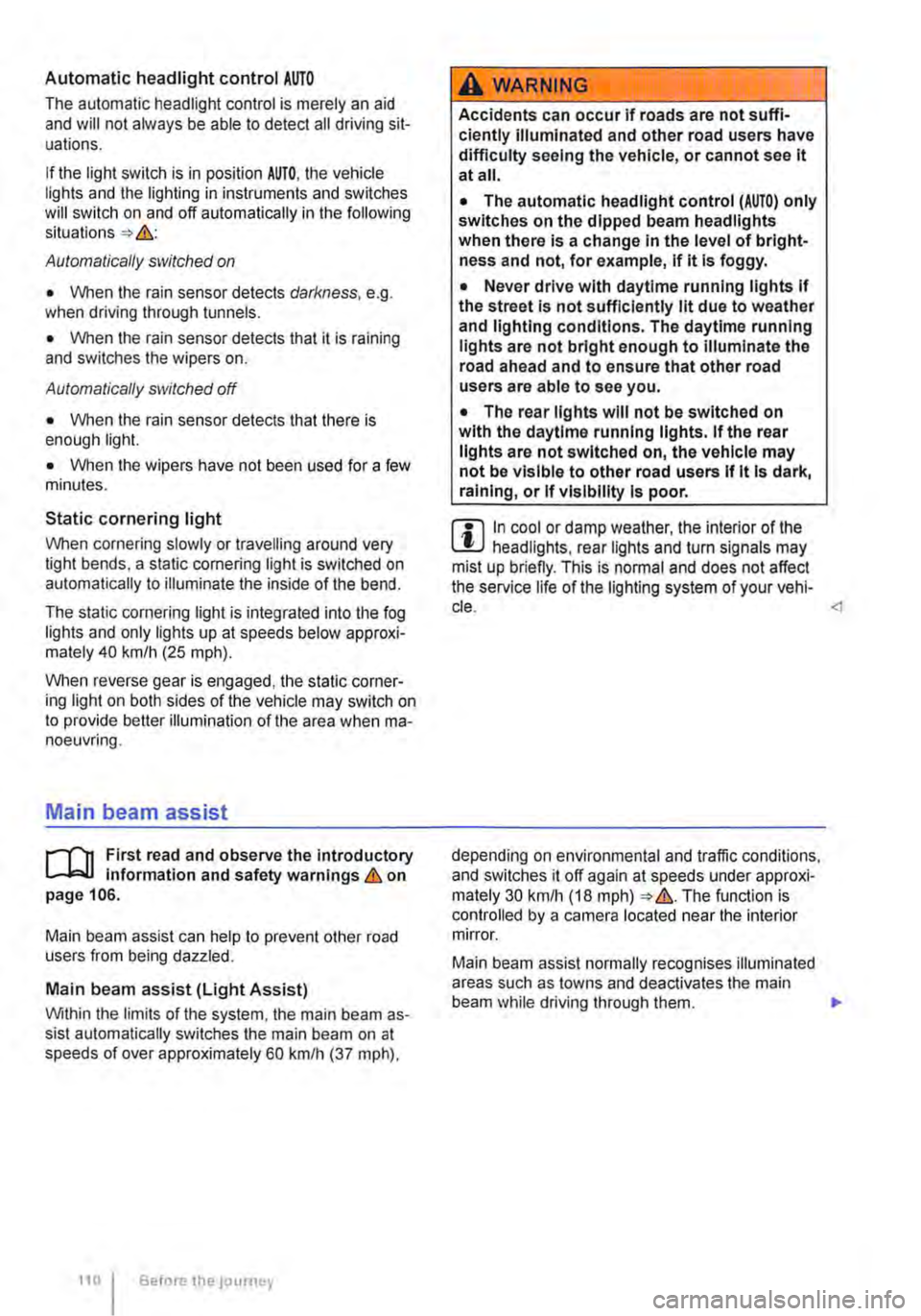
The automatic headlight control is merely an aid and will not always be able to detect all driving sit-uations.
If the light switch is in position AUTO, the vehicle lights and the lighting in instruments and switches will switch on and off automatically in the following situations => .&.:
Automatically switched on
• When the rain sensor detects darkness, e.g. when driving through tunnels.
• When the rain sensor detects that it is raining and switches the wipers on.
Automatically switched off
• When the rain sensor detects that there is enough light.
• When the wipers have not been used for a few minutes.
Static cornering light
When cornering slowly or travelling around very tight bends, a static cornering light is switched on automatically to illuminate the inside of the bend.
The static cornering light is integrated into the fog lights and only lights up at speeds below approxi-mately 40 km/h (25 mph).
When reverse gear is engaged, the static corner-ing light on both sides of the vehicle may switch on to provide better illumination of the area when ma-noeuvring.
Main beam assist
r-("'n First read and observe the introductory 1..-JcJl Information and safety warnings.&. on page 106.
Main beam assist can help to prevent other road users from being dazzled.
Main beam assist (Light Assist)
Within the limits of the system, the main beam as-sist automatically switches the main beam on at speeds of over approximately 60 kmlh (37 m ph),
110 I Before the journey
A WARNING
Accidents can occur if roads are not suffi-ciently Illuminated and other road users have difficulty seeing the vehicle, or cannot see it at all.
• The automatic headlight control (AUTO) only switches on the dipped beam headlights when there is a change In the level of bright-ness and not, for example, if it Is foggy.
• Never drive with daytime running lights if the street Is not sufficiently lit due to weather and lighting conditions. The daytime running lights are not bright enough to Illuminate the road ahead and to ensure that other road users are able to see you.
• The rear lights will not be switched on with the daytime running lights. If the rear lights are not switched on, the vehicle may not be visible to other road users If it Is dark, raining, or If visibility Is poor.
m In cool or damp weather, the interior of the l..!J headlights, rear lights and turn signals may mist up briefly. This is normal and does not affect the service life of the lighting system of your vehi-cle.
Main beam assist normally recognises illuminated areas such as towns and deactivates the main beam while driving through them. .,.
Page 135 of 486
A WARNING (Continued)
• Attach securing straps securely to the fas-tening rings.
• Loose objects in the vehicle can suddenly slide and change the way the vehicle han-dles.
• Never exceed the maximum load rating of the fastening rings when securing objects.
• Small and light objects should also be se-cured.
• Never secure a child seat to the fastening rings.
• Rotating single seats must always be turned in the direction of travel if a load is se-cured behind this seat using fastening rings.
T-shaped fastening ring
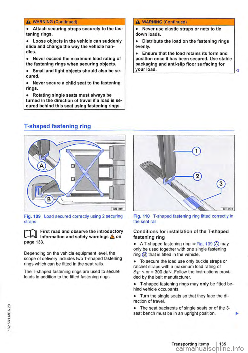
Fig. 109 Load secured correctly using 2 securing straps
il11 First read and observe the introductory L-J,.:.U information and safety warnings & on page 133.
Depending on the vehicle equipment level, the scope of delivery includes two T-shaped fastening rings which can be fitted in the seat rails.
The T-shaped fastening rings are used to secure loads in addition to the fitted fastening rings.
A WARNING (Continued)
• Never use elastic straps or nets to tie down loads.
• Distribute the load on the fastening rings evenly.
• Ensure that the load retains its form and position once it has been secured. Use stable packaging and anti-slip floor surfacing for your load.
Conditions for installation of the T-shaped fastening ring
• AT-shaped fastening ring 109 ®may only be used together with one single fastening ring® that is fitted in the vehicle.
• To secure the load use only buckle straps or ratchet straps with a maximum load rating of SrF < or= 300 daN. Follow the instructions provi-ded by the belt manufacturer.
• T-shaped fastening rings may only be fitted be-hind vehicle occupants.
• Turn the single seats so that they face the di-rection of travel.
• The seat backrests of single seats or of the 3-seat bench must be in an upright position. .,.
Transporting Items 135
Page 136 of 486
Fitting the T-shaped fastening ring
• Fit the T-shaped fastening ring parallel to the seat rail in the seat rail.
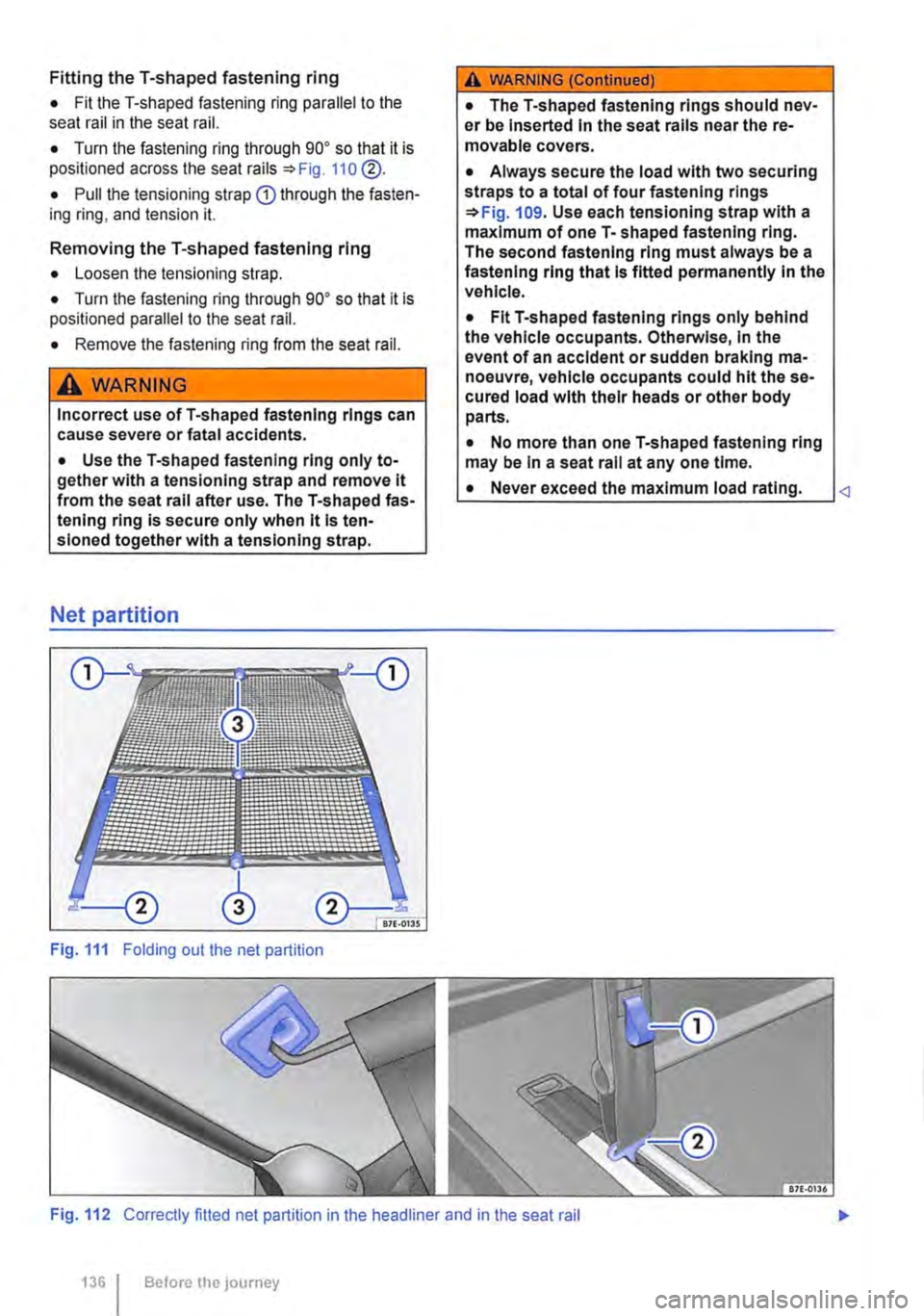
• Turn the fastening ring through go• so that it is positioned across the seat rails =:>Fig. 110 @.
• Pull the tensioning strap Q) through the fasten-ing ring, and tension it.
Removing the T-shaped fastening ring
• Loosen the tensioning strap.
• Turn the fastening ring through go• so that it is positioned parallel to the seat rail.
• Remove the fastening ring from the seat rail.
A WARNING
Incorrect use ofT-shaped fastening rings can cause severe or fatal accidents.
• Use the T-shaped fastening ring only to-gether with a tensionlng strap and remove it from the seat rail after use. The T-shaped fas-tening ring is secure only when it Is ten-sloned together with a tenslonlng strap.
Net partition
Fig. 111 Folding out the net partition
A WARNING (Continued)
• The T-shaped fastening rings should nev-er be Inserted In the seat rails near the re-movable covers.
• Always secure the load with two securing straps to a total of four fastening rings =:>Fig. 109. Use each tensloning strap with a maximum of one T-shaped fastening ring. The second fastening ring must always be a fastening ring that Is fitted permanently In the vehicle.
• Fit T-shaped fastening rings only behind the vehicle occupants. Otherwise, In the event of an accident or sudden braking ma-noeuvre, vehicle occupants could hit the se-cured load with their heads or other body parts.
• No more than one T-shaped fastening ring may be In a seat rail at any one time.
• Never exceed the maximum load rating.
1361 Before the journey