VOLKSWAGEN TRANSPORTER 2012 Owners Manual
Manufacturer: VOLKSWAGEN, Model Year: 2012, Model line: TRANSPORTER, Model: VOLKSWAGEN TRANSPORTER 2012Pages: 486, PDF Size: 69.28 MB
Page 101 of 486
Installing child seats with ISOFIX ISOFIX/i-
Size
The location of the ISO FIX anchor points is shown either by a symbol or by a label marked "ISOFIX" 79.
• Observe the warnings 97, Basic infor-mation on fitting and using child seats.
• Push the attachment arms on the child seat into the ISOFIX anchor points 79 as shown by the arrows. The child seat must click and audibly securely into place.
• Pull on both sides of the child seat to check whether the seat has clicked properly into place.
• If the child seat is fitted with a support foot, the foot must sit firmly on the floor of the vehicle.
Using insert guides
If the child seat anchor points are not directly ac-cessible, insert guides make fitting and removing the child seat easier. First attach the insert guides to the anchor points. Then secure the child seat as per the installation guide.
CD
Avoid damage to the upholstery and seat cush-ions caused by the Insert guides.
• Always pull the insert guides off the anchor points before folding the rear seat forward, or when removing the child seat.
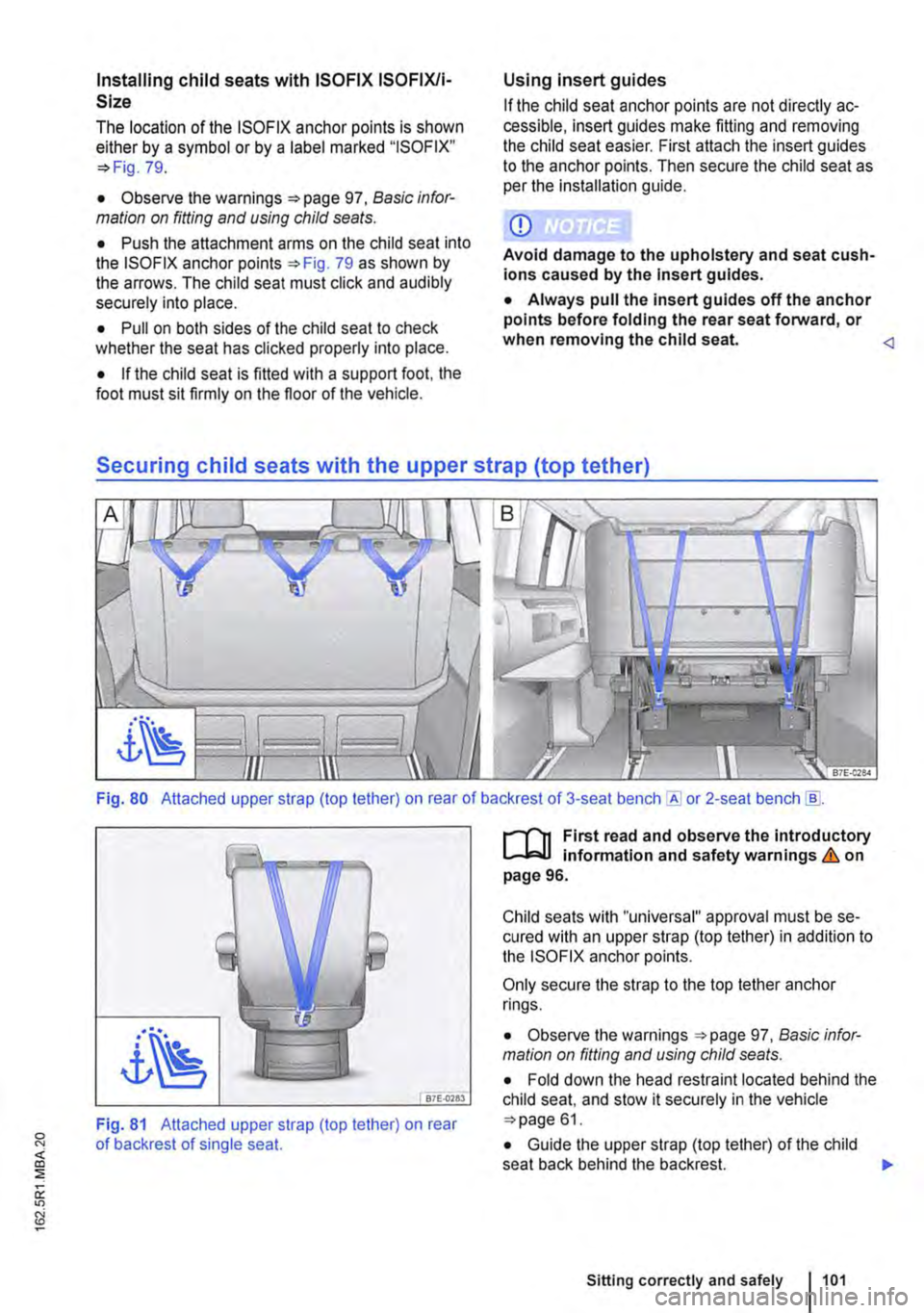
Fig. 80 Attached upper strap (top tether) on rear of backrest of 3-seat or 2-seat bench [ID.
87E-0783
Fig. 81 Attached upper strap (top tether) on rear of backrest of single seat.
r-1'11 First read and observe the Introductory L-lcJ.I Information and safety warnings & on page 96.
Child seats with "universal" approval must be se-cured with an upper strap (top tether) in addition to the ISOFIX anchor points.
Only secure the strap to the top tether anchor rings.
• Observe the warnings 97, Basic infor-mation on fitting and using child seats.
• Fold down the head restraint located behind the child seat, and stow it securely in the vehicle 61.
• Guide the upper strap (top tether) of the child seat back behind the backrest. )I>
Sitting correctly and safely 1101
Page 102 of 486
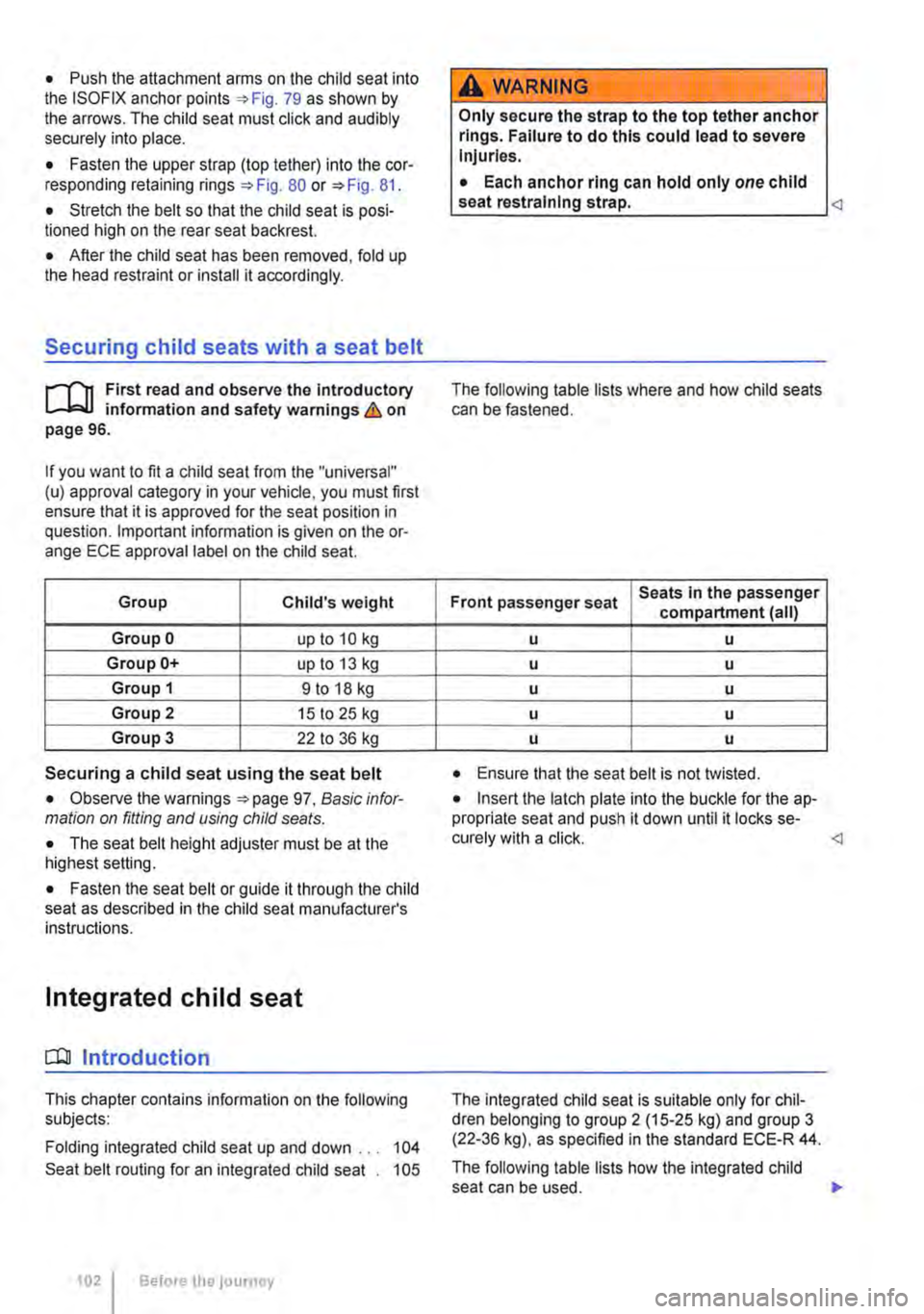
• Push the attachment arms on the child seat into the ISOFIX anchor points 79 as shown by the arrows. The child seat must click and audibly securely into place.
• Fasten the upper strap (top tether) into the cor-responding retaining rings 80 or 81.
• Stretch the belt so that the child seat is posi-tioned high on the rear seat backrest.
• After the child seat has been removed, fold up the head restraint or install it accordingly.
Securing child seats with a seat belt
r-111 First read and observe the Introductory L--lo:oU information and safety warnings & on page 96.
If you want to fit a child seat from the "universal" (u) approval category in your vehicle. you must first ensure that it is approved for the seat position in question. Important information is given on the or-ange ECE approval label on the child seat.
Group Child's weight
Group 0 up to 10 kg
Group 0+ up to 13 kg
Group 1 9 to 18 kg
Group 2 15 to 25 kg
Group 3 22 to 36 kg
Securing a child seat using the seat belt
• Observe the warnings 97, Basic infor-mation on fitting and using child seals.
• The seat belt height adjuster must be at the highest setting.
• Fasten the seat belt or guide it through the child seat as described in the child seat manufacturer's instructions.
Integrated child seat
o::n Introduction
This chapter contains information on the following subjects:
Folding integrated child seat up and down ... 104
Seat belt routing for an integrated child seat . 105
102 Before the journey
A WARNING
Only secure the strap to the top tether anchor rings. Failure to do this could lead to severe Injuries.
• Each anchor ring can hold only one child seat restraining strap.
Front passenger seat Seats In the passenger compartment (all)
u u
u u
u u
u u
u u
• Ensure that the seat belt is not twisted.
• Insert the latch plate into the buckle for the ap-propriate seat and push it down until it locks se-curely with a click.
The following table lists how the integrated child seat can be used. .,..
Page 103 of 486
Single seat in
Group Child's weight passenger compart-menta)
Group 0 up to 10 kg -
Group 0+ up to 13 kg -
Group 1 9 to 18 kg -
Group 2 15 to 25 kg 8
Group 3 22 to 36 kg 8
a) The integrated child seat is fijted depending on equipment level.
8: integrated child seat approved for this weight class.
Volkswagen Commercial Vehicles recommends that the integrated child seat be used on the single seat facing against the direction of travel for chil-dren in group 2.
For safety reasons, if the integrated child seat is used on the single seat for children in group 3, it must face the direction of travel.
The supplied side head restraint must be used for children in group 2.
The side head restraint must not be used when group 3 children use the integrated child seat.
Additional information and warnings:
• Seat belts =:. page 79
Children who are not belted in and children who are not secured using a suitable re-straint system could sustain fatal injuries if the airbags are triggered.
• Always transport children up to the age of 12 on the rear seats.
• If exceptional circumstances require you to transport a child in a rear-facing child seat on the front passenger seat, the front passen-ger front airbag must always be switched off.
• Always secure children in the vehicle in a restraint system which is suitable for their height and weight.
• Always ensure that children are properly belted In.
A WARNING
When travelling, children must be secured In the vehicle In a child seat appropriate for weight and size.
• Always secure children In the vehicle in a restraint system which is suitable for their height and weight.
• Always fasten children's seat belts cor-rectly and ensure that they assume a correct sitting position.
• The shoulder part of the seat belt must lie approximately on the centre of the shoulder and never across the neck or upper arm.
• The shoulder belt must lie close to the chest.
• The lap part of the seat belt must lie across the pelvis, not across the stomach, and always fit closely.
• If necessary, tighten the belt so that it lies snugly over the body.
• Never allow children or babies to be trans-ported on someone's lap, or held In some-one's arms.
• Always secure children under 1.5 m tall in a child seat. Using a normal seat belt could lead to injuries to the abdominal and neck areas.
• Only ever fasten one child into a child seat.
• Read and observe the information and warnings from the child seat manufacturer.
• Never leave a child in a child seat unsu-pervised or alone In the vehicle.
• Any modifications to the integrated child seat must be made only by a qualified work-shop.
• Have a child seat or parts of a child seat replaced if the child seat or any part of it be-comes damaged or if it withstands the force of a collision during an accident.
A WARNING
Loose items could be flung through the vehi-cle interior in the event of a sudden braking manoeuvre or accident. This could cause in-juries.
• Do not leave any toys or hard objects loose in the child seat or on the seat. <1
Sitting correctly and safely 103
Page 104 of 486
Folding integrated child seat up and down
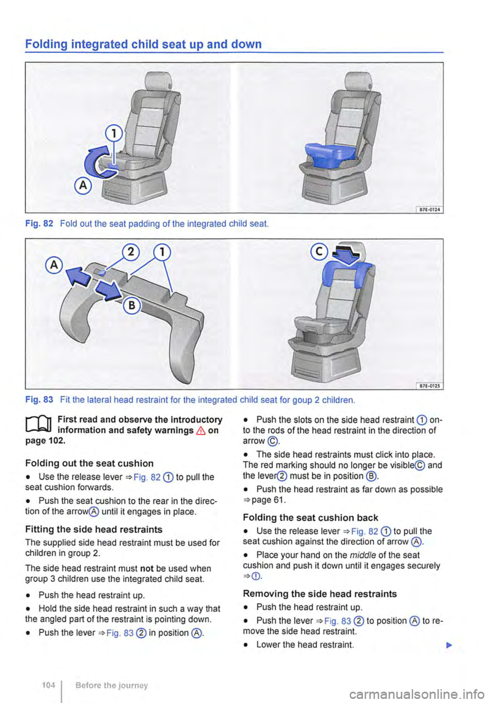
Fig. 82 Fold out the seat padding of the integrated child seat.
Fig. 83 Fit the lateral head restraint for the integrated child seat for goup 2 children.
r"'1'1t First read and observe the Introductory information and safety warnings & on page 102.
Folding out the seat cushion
• Use the release lever 82 Q) to pull the seat cushion forwards.
• Push the seat cushion to the rear in the direc-tion of the arrow@ until it engages in place.
Fitting the side head restraints
The supplied side head restraint must be used for children in group 2.
The side head restraint must not be used when group 3 children use the integrated child seat.
• Push the head restraint up.
• Hold the side head restraint in such a way that the angled part of the restraint is pointing down.
• Push the lever 83 ®in position@.
104 Before the journey
• Push the slots on the side head restraint Q) on-to the rods of the head restraint in the direction of arrow@.
• The side head restraints must click into place. The red marking should no longer be visible@ and the lever@ must be in position @.
• Push the head restraint as far down as possible 61.
Folding the seat cushion back
• Use the release lever 82 Q) to pull the seat cushion against the direction of arrow @.
• Place your hand on the middle of the seat cushion and push it down until it engages securely
Removing the side head restraints
• Push the head restraint up.
• Push the lever 83 ® to position ® to re-move the side head restraint.
• Lower the head restraint. ...
Page 105 of 486
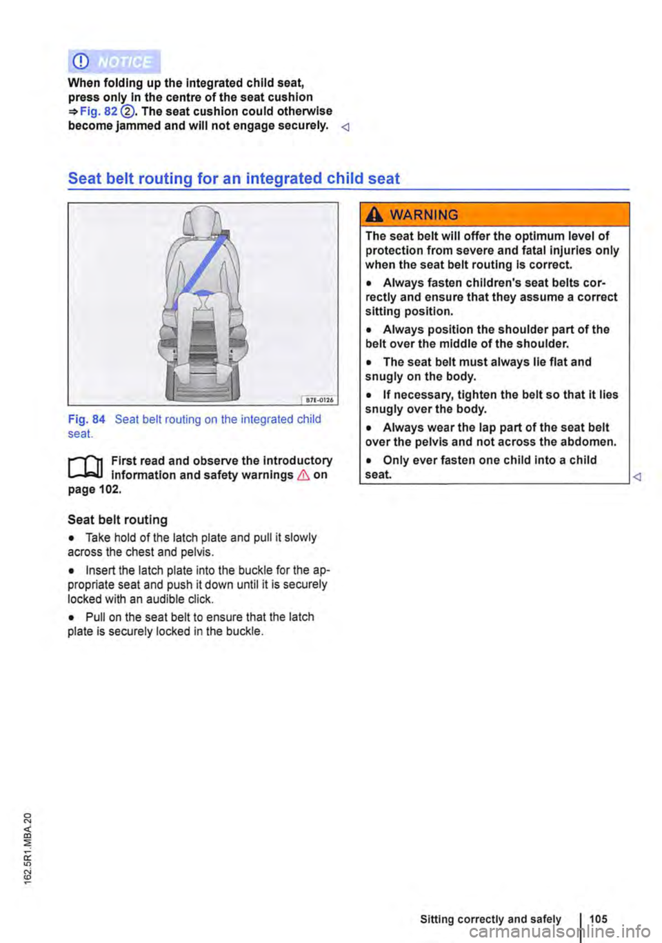
Fig. 84 Seat belt routing on the integrated child seat.
r-flt First read and observe the Introductory 1.-J,::.U Information and safety warnings & on page 102.
Seat belt routing
• Take hold of the latch plate and pull it slowly across the chest and pelvis.
• Insert the latch plate into the buckle for the ap-propriate seat and push it down until it is securely locked with an audible click.
• Pull on the seat belt to ensure that the latch plate is securely locked in the buckle.
A WARNING
The seat belt will offer the optimum level of protection from severe and fatal injuries only when the seat belt routing Is correct.
• Always fasten children's seat belts cor-rectly and ensure that they assume a correct sitting position.
• Always position the shoulder part of the belt over the middle of the shoulder.
• The seat belt must always lie flat and snugly on the body.
• If necessary, tighten the belt so that lt lies snugly over the body.
• Always wear the lap part of the seat belt over the pelvis and not across the abdomen.
• Only ever fasten one child into a child
Sitting correctly and safely 105
Page 106 of 486
Lights and vision
Lights
0::0 Introduction
This chapter contains information on the following subjects:
Indicator lamps . . . . . . . . . . . . . . . . . 106
Turn signal and main beam lever . . 107 Switching lights on and off . . . . . . . . 108
Lights and vision -functions . . . . . . . . . . . . . . 109
Main beam assist ....................... 110
Masking or switching over headlights for driving abroad . . . . . . . . . 111
Coming Home and Leaving Home functions (orientation lighting).............. 112
Headlight range control, instrument and switch lighting . . . . . 113 Interior and reading lights . . . . . . . . . 114
Observe any country-specific regulations when us-ing vehicle lighting.
The driver is responsible for the correct headlight position and the correct headlight setting.
Additional information and warnings:
• Exterior views ""page 5
• Volkswagen information system =oo page 24
• Changing bulbs =oo page 432
Indicator lamps
A WARNING
Accidents and serious injuries can occur if roads are not sufficiently Illuminated and oth-er road users have difficulty seeing the vehi-cle, or cannot see it at all.
• Always switch the dipped beam head-lights on if it is dark, raining or visibility is poor.
A WARNING
Setting headlights too high, and the incorrect use of the main beam, could distract and daz-zle other road users. This can lead to acci-dents and serious injuries.
• Always ensure that the headlights are ad-j usted correctly.
• Never use the main beam or the headlight flasher if other road users could be dazzled.
[Qj First read and observe the introductory information and safety warnings & on page 106.
Indicator lamps in the instrument cluster
Lit up Possible cause Solution
Vehicle lighting not working partially or corn-Change the appropriate bulb 432. If all of the bulbs are in working order. go to a pletely. qualified workshop.
' Rear fog light switched on. J", =oopage 109.
,( The fog light is switched on.
Turn signal, left or right.
r The indicator lamp will flash twice as fast if If necessary, check the vehicle lights and the one of the turn signals on the vehicle or trailer trailer lights. is not working.
'111 Trailer turn signals in operation. 139.
106 Before the journey
Page 107 of 486
Lit up Possible cause Solution
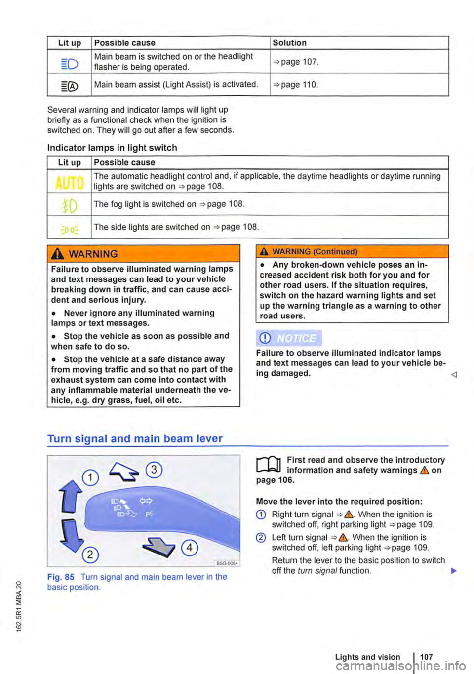
Main beam is switched on or the headlight 107. flasher is being operated.
Main beam assist (light Assist) is activated. 110.
Several warning and indicator lamps will light up briefly as a funclional check when the ignition is switched on. They will go out after a few seconds.
Indicator lamps in light switch
Lit up Possible cause
The automatic headlight control and, if applicable, the daytime headlights or daytime running Jl lights are switched on 108 .
.fD The fog light is switched on 108.
I) I The side lights are switched on 108.
A WARNING
Failure to observe illuminated warning lamps and text messages can lead to your vehicle breaking down in traffic, and can cause acci-dent and serious injury.
• Never Ignore any illuminated warning lamps or text messages.
• Stop the vehicle as soon as possible and when safe to do so.
• Stop the vehicle at a safe distance away from moving traffic and so that no part of the exhaust system can come into contact with any inflammable material underneath the ve-hicle, e.g. dry grass, fuel, oil etc.
Turn signal and main beam lever
A WARNING (Continued)
• Any broken-down vehicle poses an In-creased accident risk both for you and for other road users. If the situation requires, switch on the hazard warning lights and set up the warning triangle as a warning to other road users.
CD
Failure to observe illuminated indicator lamps and text messages can lead to your vehicle be-ing damaged.
...--r'l1 First read and observe the introductory l.-Jo:JJ information and safety warnings & on page 106.
Move the lever into the required position:
CD Right tu m signal &. VVhen the ignition is switched off, right parking light 109.
@ Left turn signal &. VVhen the ignition is switched off, left parking light 109.
Return the lever to the basic position to switch
<]
Fig. 85 Turn signal and main beam lever in the basic position.
off the turn signal function. 1>
Lights and vision 1107
Page 108 of 486
@ Main beam headlights switched on &. The indicator lamp m in the instrument cluster lights up.
Pull the lever briefly in the direction of the ar-row @to switch off the main beam headlights.
@ Operate headlight flasher. The headlight flash-er comes on for as long as the lever is pulled. The indicator lamp ID lights up.
Lane change flash
To operate the lane change flash, push the lever up or down to the point where you incur resistance and then release the lever. The turn signal flashes three times.
This lane change flash function can be deactivated at a qualified workshop.
A WARNING
Incorrect use of turn signals, a failure to use turn signals, or forgetting to switch off a turn signal can confuse other road users. This can lead to accidents and serious Injuries.
Switching lights on and off
A WARNING (Continued)
• Always activate the turn signal In good time when changing lanes and performing overtaking or turning manoeuvres.
• Always switch off the turn signal once the lane change or overtaking or turning ma-noeuvre has been completed.
A WARNING
Incorrect use of the main beam headlights can lead to accidents and serious Injuries as the main beam headlights can distract and dazzle other road users.
m The turn signal will only work when the igni-m lion is switched on. The hazard warning lights also work when the ignition is switched off 411.
m If one turn signal fails on the vehicle or on the m trailer, the indicator lamp will start flashing twice as fast.
m The main beam headlights can only be m switched on if the dipped beam headlights are already on.
l"'""'rT1 First read and observe the Introductory L--J,::.,U information and safety warnings & on page 106.
Observe any country-specific regulations when us-ing vehicle lighting.
1081 Before the; journey
In vehicles with a factory-fitted towing bracket 139, the vehicle's rear fog lights are switched off automatically if a trailer with rear fog lights is electrically connected to the vehicle. .,.
Page 109 of 486
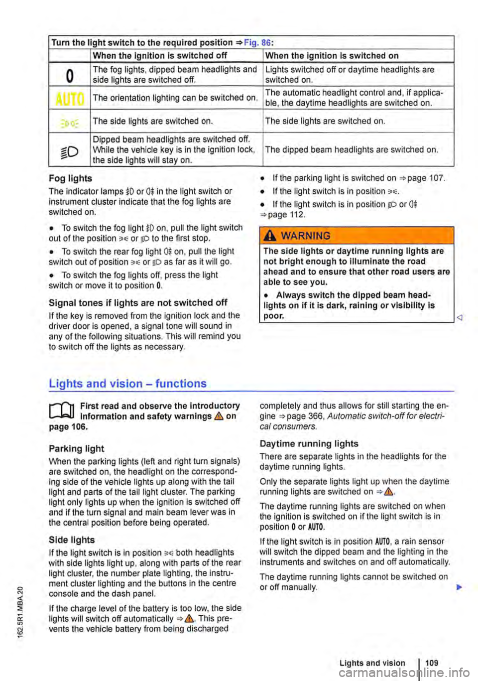
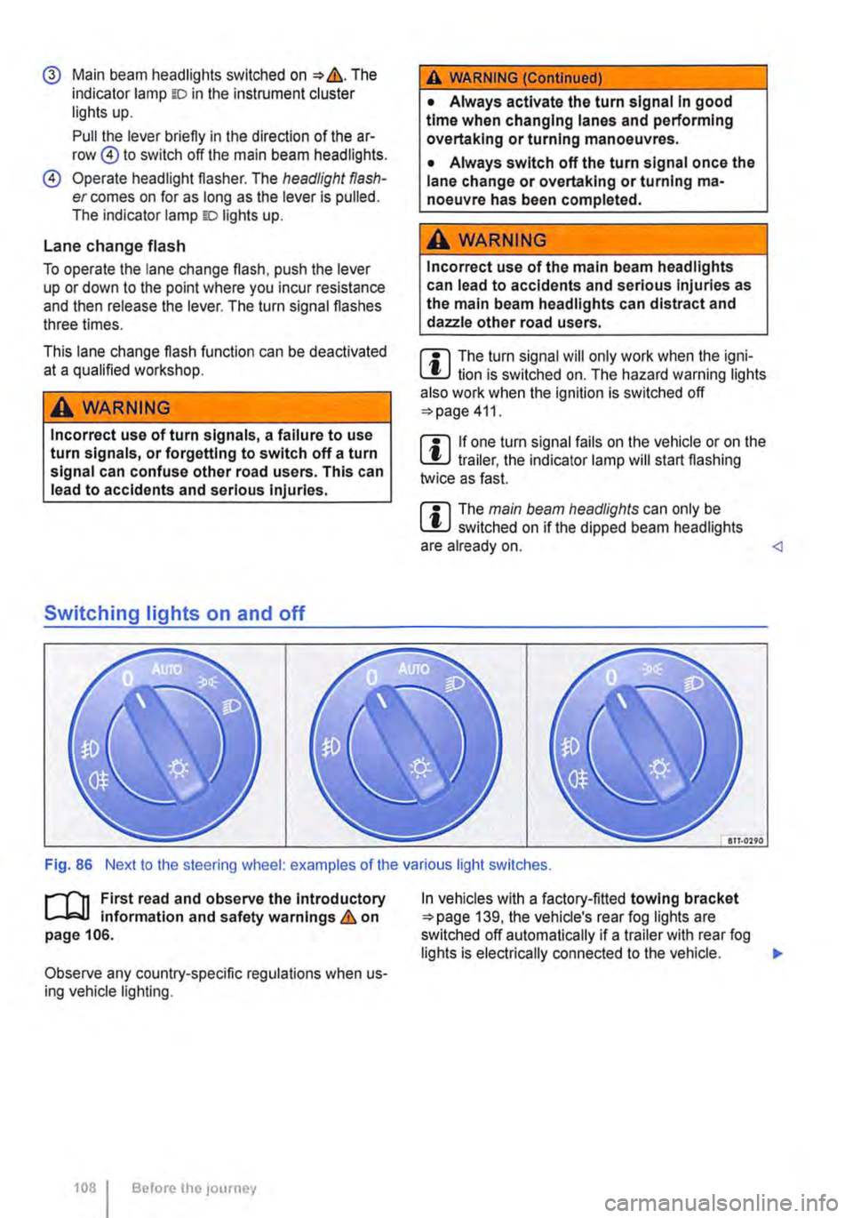
Turn the light switch to the required position 86:
When the Ignition Is switched off
0 The fog lights, dipped beam headlights and side lights are switched off.
,. The orientation lighting can be switched on.
) , The side lights are switched on.
Dipped beam headlights are switched off.
"'D While the vehicle key is in lhe ignition lock, the side lights will stay on.
Fog lights
The indicator lamps or 0$ in the light switch or Instrument cluster indicate that the fog lights are switched on.
• To switch the fog light on, pull the light switch out of the position "" or tD to the first stop.
• To switch the rear fog light 0$ on, pull the light switch out of position ,.,, or gD as far as it will go.
• To switch the fog lights off, press the light switch or move it to position 0.
Signal tones if lights are not switched off
If the key is removed from the ignition lock and the driver door is opened, a signal tone will sound in any of the following situations. This will remind you to switch off the lights as necessary.
Lights and vision -functions
1""1'11 First read and observe the introductory L-lo:.U Information and safety warnings & on page 106.
Parking light
When the parking lights (left and right turn signals) are switched on, the headlight on the correspond-ing side of the vehicle lights up along with the tail light and parts of the tail light cluster. The parking light only lights up when the Ignition is switched off and if the turn signal and main beam lever was in the central position before being operated.
Side lights
If the light switch is in position ;.o; both headlights with side lights light up, along with parts of the rear light cluster, the number plate lighting, the instru-ment cluster lighting and the buttons in the centre console and the dash panel.
If the charge level of the battery is too low, the side lights will switch off automatically &. This pre-vents the vehicle battery from being discharged
When the Ignition Is switched on
Lights switched off or daytime headlights are switched on.
The automatic headlight control and, if applica-ble, the daytime headlights are switched on.
The side lights are switched on.
The dipped beam headlights are switched on.
• If the parking light is switched on 107.
• If the light switch is in position '"'·
• If the light switch is in position iD or 0$ 112.
A WARNING
The side lights or daytime running lights are not bright enough to Illuminate the road ahead and to ensure that other road users are able to see you.
• Always switch the dipped beam head-lights on if it is dark, raining or visibility Is
completely and thus allows for still starting the en-gine 366, Automatic switch-off for electri-cal consumers.
Daytime running lights
There are separate lights in the headlights for the daytime running lights.
Only the separate lights light up when the daytime running lights are switched on &.
The daytime running lights are switched on when the ignition is switched on if the light switch is in position 0 or AUTO.
If the light switch is in position AUTO, a rain sensor will switch the dipped beam and the lighting in the instruments and switches on and off automatically.
The daytime running lights cannot be switched on or off manually. ,._
Lights and vision 1109
Page 110 of 486
Automatic headlight control AUTO
The automatic headlight control is merely an aid and will not always be able to detect all driving sit-uations.
If the light switch is in position AUTO, the vehicle lights and the lighting in instruments and switches will switch on and off automatically in the following situations => .&.:
Automatically switched on
• When the rain sensor detects darkness, e.g. when driving through tunnels.
• When the rain sensor detects that it is raining and switches the wipers on.
Automatically switched off
• When the rain sensor detects that there is enough light.
• When the wipers have not been used for a few minutes.
Static cornering light
When cornering slowly or travelling around very tight bends, a static cornering light is switched on automatically to illuminate the inside of the bend.
The static cornering light is integrated into the fog lights and only lights up at speeds below approxi-mately 40 km/h (25 mph).
When reverse gear is engaged, the static corner-ing light on both sides of the vehicle may switch on to provide better illumination of the area when ma-noeuvring.
Main beam assist
r-("'n First read and observe the introductory 1..-JcJl Information and safety warnings.&. on page 106.
Main beam assist can help to prevent other road users from being dazzled.
Main beam assist (Light Assist)
Within the limits of the system, the main beam as-sist automatically switches the main beam on at speeds of over approximately 60 kmlh (37 m ph),
110 I Before the journey
A WARNING
Accidents can occur if roads are not suffi-ciently Illuminated and other road users have difficulty seeing the vehicle, or cannot see it at all.
• The automatic headlight control (AUTO) only switches on the dipped beam headlights when there is a change In the level of bright-ness and not, for example, if it Is foggy.
• Never drive with daytime running lights if the street Is not sufficiently lit due to weather and lighting conditions. The daytime running lights are not bright enough to Illuminate the road ahead and to ensure that other road users are able to see you.
• The rear lights will not be switched on with the daytime running lights. If the rear lights are not switched on, the vehicle may not be visible to other road users If it Is dark, raining, or If visibility Is poor.
m In cool or damp weather, the interior of the l..!J headlights, rear lights and turn signals may mist up briefly. This is normal and does not affect the service life of the lighting system of your vehi-cle.
Main beam assist normally recognises illuminated areas such as towns and deactivates the main beam while driving through them. .,.