VOLKSWAGEN TRANSPORTER 2012 Owners Manual
Manufacturer: VOLKSWAGEN, Model Year: 2012, Model line: TRANSPORTER, Model: VOLKSWAGEN TRANSPORTER 2012Pages: 486, PDF Size: 69.28 MB
Page 281 of 486
Steering
CJ:n Introduction
This chapter contains information on the following subjects:
Information on steering . . . . . . . . . . . . . . . . . . . 281
Additional information and warnings:
• Starting and stopping the engine 257
• Battery 362
• Tow-starting and towing 446
Information on steering
r--f"n First read and observe the introductory L-la.LI infonmation and safety warnings & on page 281.
Locking the steering wheel
• When the vehicle key has been removed, turn the steering wheel slightly until you hear the lock-ing pin engage.
The steering should be locked every time you leave the vehicle to make il more difficult for the vehicle to be stolen.
Unlocking the steering wheel
• Turn the steering wheel slightly to lake the load off the steering lock mechanism. Hold the steering wheel in this position and tu m the vehicle key clockwise out of position 217 @.
A WARNING
If the power steering is not working, the steering wheel is difficult to turn, which makes it difficult to steer the vehicle.
• The power steering only functions when the engine Is running.
• Never allow the vehicle to roll if the engine is switched off.
• Never remove the vehicle key from the ig-nition lock when the vehicle is in motion. The steering lock may be activated and you will no longer be able to steer the vehicle.
With power steering, the steering assistance is au-tomatically matched to vehicle speed, the steering wheel torque and the steering wheel angle. The power steering will only function when the engine is running.
You will need considerably more strength than nor-mal to steer the vehicle if lhe power steering is re-duced or has failed completely.
Page 282 of 486
Driver assist systems
Pull-away assist systems
cr:n Introduction
This chapter contains information on the following subjects:
Warning and indicator lamps . . . . . . . . . . . . . . 282
Start/stop system . . . . . . . . . . . . . . . . • . . . . . . . 283
Hill Hold Assist . . . . . . . . . . . . . . . . . . . . . . . . . . 284
Hill Descent Assist . . . . . . . . . . . . . . . . . . . . . . . 285
Rear axle differential lock . . . . . . . . . . . . . . . . . 286
Additional information and warnings:
• Volkswagen information system =>page 24
• Braking, stopping and parking =>page 269
• Battery =>page 362
• Wheels and tyres =>page 367
• Accessories, modifications, repairs and renewal of parts =>page 394
• Jump starting =>page 443
Warning and indicator lamps
A WARNING
The intelligent technology of the pull-away assist systems cannot overcome the laws of physics or system-related vehicle limitations. Never let the extra convenience afforded by pull-away assist systems tempt you into tak-ing any risks when driving-this can cause accidents.
• Unintentional vehicle movements can cause serious Injury.
• The pull-away assist systems cannot re-place the driver's full concentration.
• Always adapt your speed and driving style to suit visibility, weather, road and traffic con-ditions.
• Pull-away assist systems cannot hold the vehicle in all hill start situations or brake it sufficiently on all slopes going downhill (e.g. if the ground is slippery or icy).
Lit up Possible cause
Rear axle differential lock switched on . ...
Hill Descent Assist switched on.
(A) The start/stop system is available, automat-ic engine stop is active.
ex;
The start/stop system is not available. OR: the start/stop system has switched off the engine automatically.
Flashes Possible cause
The rear axle differential lock cannot be .... switched on .
Hill Descent Assist is regulating.
Several warning and indicator lamps will light up briefly as a functional check when the ignition is switched on. They will go out after a few seconds. .,..
282 I While drivmg
Solution
=>page 286
=>page 285
=>page 283
Check whether all technical requirements have been fulfilled. If necessary, make sure that all technical requirements are fulfilled =>page 283.
Solution
=>page 286
=>page 285
Page 283 of 486
A WARNING
Failure to observe illuminated warning lamps and text messages can lead to your vehicle breaking down in traffic, and can cause acci-dent and serious injury.
• Never ignore any illuminated warning lamps or text messages.
Start/stop system
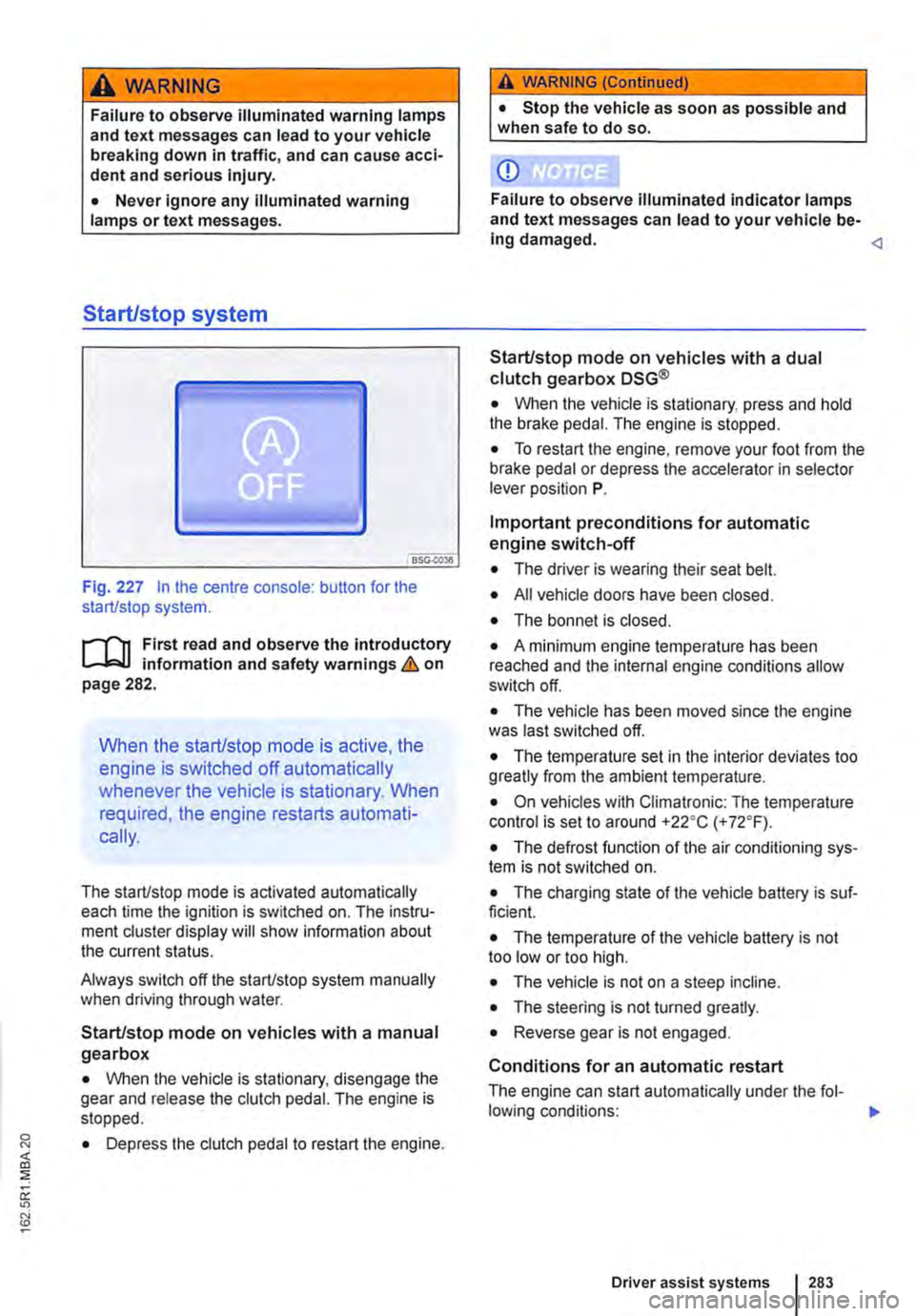
Fig. 227 In the centre console: button for the start/stop system.
r--flt First read and observe the introductory l-J,::JJ information and safety warnings & on page 282.
When the start/stop mode is active, the
engine is switched off automatically
whenever the vehicle is stationary. When
required, the engine restarts automati-
cally.
The start/stop mode is activated automatically each time the ignition is switched on. The instru-ment cluster display will show information about the current status.
Always switch off the start/stop system manually when driving through water.
Start/stop mode on vehicles with a manual gearbox
• When the vehicle is stationary, disengage the gear and release the clutch pedal. The engine is stopped.
• Depress the clutch pedal to restart the engine.
A WARNING (Continued)
• Stop the vehicle as soon as possible and when safe to do so.
CD
Failure to observe illuminated indicator lamps and text messages can lead to your vehicle be-ing damaged.
• When the vehicle is stationary, press and hold the brake pedal. The engine is stopped.
• To restart the engine, remove your foot from the brake pedal or depress the accelerator in selector lever position P.
Important preconditions for automatic engine switch-off
• The driver is wearing their seat belt.
• All vehicle doors have been closed.
• The bonnet is closed.
• A minimum engine temperature has been reached and the internal engine conditions allow switch off.
• The vehicle has been moved since the engine was last switched off.
• The temperature set in the interior deviates too greatly from the ambient temperature.
• On vehicles with Climatronic: The temperature control is set to around +22oC (+ 72°F).
• The defrost function of the air conditioning sys-tem is not switched on.
• The charging state of the vehicle battery is suf-ficient.
• The temperature of the vehicle battery is not too low or too high.
• The vehicle is not on a steep incline.
• The steering is not turned greatly.
• Reverse gear is not engaged.
Conditions for an automatic restart
The engine can start automatically under the fol-lowing conditions: IIJ>
Driver assist systems 283
Page 284 of 486
• On vehicles with Climatronic: if the temperature inside the vehicle substantially increases or de-creases.
• When the vehicle starts rolling or brake support is required.
• If the voltage of the vehicle battery falls.
Conditions that necessitate a manual key start
The engine has to be started manually with the ve-hicle key in the following conditions:
• If the driver unfastens their seat belt.
• If a vehicle door is opened.
• If the bonnet is opened.
Switching the start/stop system on and off manually
• Press the @ button in the centre console 227.
• If the start/stop system has been deactivated, the indicator lamp in the button lights up.
The engine will start immediately if the vehicle Is In stop mode when the system is switched off man-ually with the @ button.
Hill Hold Assist
r--T'n First read and observe the Introductory L-I=JJ information and safety warnings & on page 282.
A WARNING
The brake servo and the power steering will not function If the engine Is switched off.
• Never allow the vehicle to roll if the engine is switched off.
• The start/stop system must be switched off if work Is to be carried out In the engine compartment.
CD
If the start/stop system Is used in very high outside temperatures over a long period, the vehicle battery can be damaged.
m In some cases. it will be necessary to restart L!J the engine manually with the vehicle key. Fol-low any corresponding messages on the instru-ment cluster display.
m At low speeds, the engine can be started L!J again if it has stalled by immediately pressing the clutch pedal.
holds the vehicle when pulling away on
an incline.
The Hill Hold Assist function is automatically activated if the following conditions are met
Points 1 to 3 must be fulfilled at the same time·
Manual gearbox DSG® dual clutch gearbox
1. On an incline, the stationary vehicle must be held in position with the footbrake until the vehicle starts moving.
2. The engine is running smoothly.
3. The driver door is closed.
4. Fully depress the clutch pedal and move the gear stick to the first gear position if you want to The driving mode R, D or S has been selected. drive forwards up a hill or to the R position if you want to reverse up a hill.
In order to start moving, remove your foot from To start moving, remove your foot from the brake the brake pedal, then simultaneously release the pedal and press the accelerator immediately. clutch pedal (the clutch engages) and press the The brake will gradually be released as the accelerator. The brake will gradually be re-vehicle pulls away. leased as the clutch Is engaged.
284 I While driving
Page 285 of 486
The Hill Hold Assist function will be deactivated immediately:
Manual gearbox I DSG® dual clutch gearbox
1. As soon as one of the conditions indicated on page 284, The Hill Hold Assist function is automati-cally activated if the following conditions are met is not fulfilled.
2. If the vehicle does not pull away within 2 seconds.
3. If the engine is not running smoothly or there is an engine fault.
4. If the engine is switched off or has stalled. I If the engine is switched off.
Hill Descent Assist
Fig. 228 In the centre console: button for switch-ing the Hill Descent Assist on and off.
l"'""'('n First read and observe the Introductory L-W.I Information and safety warnings & on page 282.
The Hill Descent Assist system supports
the driver when driving down a steep in-
cline by actively braking the vehicle.
The Hill Descent Assist reduces the engine speed and brakes actively so that the vehicle travels con-stantly at walking speed =>&.
The requirement for regulation is, among other things, that the ground allows enough grip. The Hill Descent Assist system cannot fulfil its function when driving down an icy or slippery slope.
Hill Descent Assist is regulating
• If the Hill Descent Assist is switched on using the button and the indicator lamp lights up.
• AND: the speed is less than 30 km/h (19 mph).
• AND: the gradient is at least 10%.
• AND: if the accelerator and brake are not de-pressed.
• AND: if the engine is running.
Regulation is stopped if the vehicle is accelerated or braked by the driver during regulation. The regu-lation restarts once the requirements are met again.
Hill Descent Assist does not regulate
• If the gradient is less than 10%.
• OR: The speed is greater than 30 km/h (19 mph).
• OR: If the driver brakes or accelerates.
A WARNING
Always be prepared to brake the vehicle. Ac-cidents and Injuries could occur if this is not ensured.
• The Hill Descent Assist system is only a support function and may not be able to brake the vehicle sufficiently In all situations when driving downhill.
• The vehicle may accelerate despite the Hill Descent Assist system.
• To switch the Hill Descent Assist on, press the @=>Fig. 228 button in the centre console at speeds under approximately 30 km/h (19 mph). The indicator in the instrument cluster dis-play lights up. The indicator lamp flashes when the Hill Descent Assist system is applying the brake.
r::l The Hill Descent Assist system also works if W you reverse down a slope.
Driver assist systems 285
Page 286 of 486
Rear axle differential lock
OSG-0041
Fig. 229 On the dash panel: button for rear axle differential lock
i""('n First read and observe the introductory information and safety warnings & on page 282.
If the rear-axle differential lock is switched on, the vehicle has better traction on difficult ground and
Switching the rear axle differential lock on
and off
• To switch the rear axle differential lock on, press the 229 button on the dash panel at speeds under approximately 45 krnlh (28 mph) The indicator lamp r. lights up in the instru-ment cluster.
• Press button , Fig. 229 in dash panel again to switch off the rear-axle differential lock. The indica-tor lamp r. in the instrument cluster goes out.
If the engine is switched off with the rear axle dif-ferential lock switched on, the rear axle differential lock remains switched on for roughly another 30 seconds.
Not switching the rear axle differential lock on
• If you are driving on well-surfaced roads &.
• If the vehicle is being towed.
• If the brakes are being tested on a rolling road test bed.
286 I While dnving
Rear-axle differential lock cannot be switched on
The rear axle differential lock cannot be switched on in the following situations:
• if there is a large difference in the speed of ro-tation of the rear wheels
• if the drive train is loaded heavily
• If the mechanical teeth of the rear-axle differen-tial lock are '1ooth to tooth": the indicator light r. in the instrument cluster flashes.
A WARNING
Never switch the rear axle differential lock on If you are driving on a solid road surface, the vehicle is being towed or if the tyres have no traction.
• Your steering will be greatly Impaired when the rear axle differential lock has been switched on. This could mean that you lose control over the vehicle and cause serious In-juries.
CD
Switching the rear axle differential lock on while being towed can damage the drive train.
m If the rear axle differential lock is switched off W when driving through a bend, this may cause a small shudder to go through the vehicle. This is caused by the release of wind-up in the drive train. This is normal and is not a indication of damage to the vehicle.
m If you drive through bends with the rear axle W differential lock switched on, the wheels "rub" on the road surface. You might be able to hear this. The ''rubbing" of the tyres -especially on solid ground -will lead to increased wear on the tyres.
Page 287 of 486
ParkPilot
o:n Introduction
This chapter contains information on the following subjects:
ParkPilot only at rear . . 288 ParkPilot front and rear . . . 289
ParkPilot signal tones and displays . 290
The Park Pilot assists the driver when
parking and manoeuvring.
The ultrasound sensors in the bumpers transmit and receive ultrasound waves. The electronic sys-tem uses the ultrasound waves (i.e. transmission, reflection from the obstacle and reception) to cal-culate the distance between the bumper and the obstacle.
Additional information and warnings:
• Exterior views =:o page 5
• Braking, stopping and parking =:o page 269
• Reversing camera (Rear Assist) =:o page 291
• Cleaning and caring for the vehicle exterior =:.page 380
• Accessories, modifications, repairs and renewal of parts =:o page 394
• Radio or navigation system =:o Booklet Radio, provision for mobile telephone, infotainment sys-tem, navigation system
A WARNING
ParkPilot technology cannot overcome sys-tem-related vehicle limitations. The ParkPilot cannot replace the full concentration of the driver.
• Unintentional vehicle movements can cause serious injury.
• Always adapt your speed and driving style to suit visibility, weather, road and traffic con-ditions.
• Ultrasound sensors have blind spots in which obstacles and people cannot be detec-ted.
• Always check the area around the vehicle as the ultrasound sensors will not always de-tect infants, animals and objects.
A WARNING (Continued)
• Certain surfaces of objects and clothes cannot reflect the signals from the ultrasound sensors. The system is unable to detect these objects or people wearing this type of clothing, or they may be detected incorrectly.
• External sources of sound can affect the signals of the ultrasound sensors. This may prevent the system from recognising people or objects.
CD
Various factors can negatively Impact the Park-Pilot functions or lead to damage to the vehicle and objects in the area surrounding the vehi-cle.
• The ultrasound sensors may not always be able to detect objects such as trailer drawbars, thin rails, fences, posts, trees and open or opening boot lids. This can result in damage to your vehicle.
• If the ParkPilot has detected an obstacle and issued a warning, the obstacle may move out of the detection range of the ultrasound sensors as the vehicle approaches it, particu-larly if the object is very high or very low. These objects are no longer registered.
• The vehicle can sustain considerable dam-age if the warning given by the ParkPiiot is ig-nored.
• Ultrasound sensors can be displaced or damaged through Impacts, e.g. when parking.
• The ultrasound sensors must be kept clean and free of ice and snow, and must not be cov-ered up by stickers or other objects, as this will prevent the system from working properly.
• Repainting the ultrasound sensors can im-pair the function of the Park Pilot.
• The ultrasound sensors should only be sprayed briefly when cleaning with pressure hoses and steam cleaners. The steam/hose nozzle must always be kept more than 10 cm away from the ultrasound sensors.
• Sources of noise can lead to errors in the ParkPilot system, e.g. rough asphalt, cobble-stones, induction loops, building equipment, or interference from other vehicles.
Driver assist systems 287
Page 288 of 486
CD
• In some cases water and ice on the ultra-sound sensors could be registered as an ob-struction.
• Any equipment that has been retrofitted to the vehicle, e.g. bicycle carriers or number plate holders, can prevent the ParkPIIot from fu nctlonlng properly.
m Volkswagen Commercial Vehicles recom-L!J mends that drivers practise using the ParkPi-lot in a traffic-calmed area or car park to allow them to familiarise themselves with the system and its functions.
ParkPilot only at rear
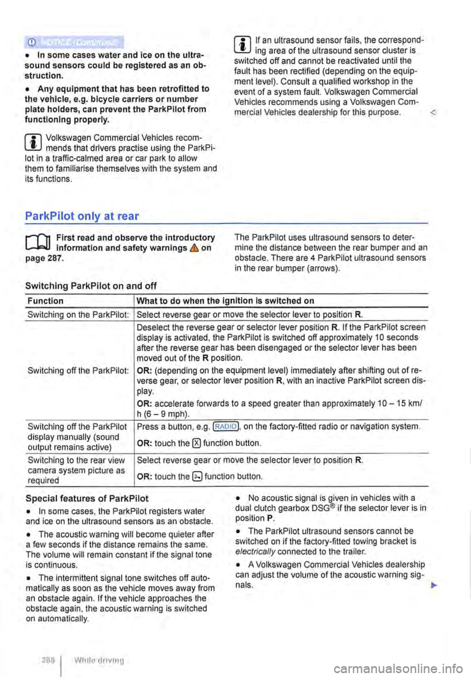
,....-m First read and observe the introductory L-J.:.I.I Information and safety warnings & on page 287.
Switching ParkPilot on and off
m If an ultrasound sensor fails, the correspond-L!J ing area of the ultrasound sensor cluster is switched off and cannot be reactivated until the fault has been rectified (depending on the equip-ment level). Consult a qualified workshop in the event of a system fault. Volkswagen Commercial Vehicles recommends using a Volkswagen Com-mercial Vehicles dealership for this purpose.
Function What to do when the Ignition Is switched on
Switching on the ParkPilot:
Switching off the ParkPilot:
Switching off the ParkPilot display manually (sound output remains active)
Switching to the rear view camera system picture as required
Select reverse gear or move the selector lever to position R.
Deselect the reverse gear or selector lever position R. If the ParkPilot screen display is activated, the ParkPilot is switched off approximately 10 seconds after the reverse gear has been disengaged or the selector lever has been moved out of the R position.
OR: (depending on the equipment level) immediately after shifting out of re-verse gear, or selector lever position R, with an inactive ParkPilot screen dis-play.
OR: accelerate forwards to a speed greater than approximately 1 0-15 km/ h (6-9 mph).
Press a button, e.g.(RADIOl. on the factory-fitted radio or navigation system.
OR: touch the 0 function button.
Select reverse gear or move the selector lever to position R.
OR: touch the button.
Special features of ParkPilot • No acoustic signal is given in vehicles with a dual clutch gearbox DSG® if the selector lever is in position P. • In some cases, the ParkPilot registers water and ice on the ultrasound sensors as an obstacle.
• The acoustic warning will become quieter after a few seconds if the distance remains the same. The volume will remain constant if the signal tone is continuous.
• The intermittent signal tone switches off auto-matically as soon as the vehicle moves away from an obstacle again. If the vehicle approaches the obstacle again, the acoustic warning is switched on automatically.
288 I While driving
• The ParkPilot ultrasound sensors cannot be switched on if the factory-fitted towing bracket is electrically connected to the trailer.
• A Volkswagen Commercial Vehicles dealership can adjust the volume of the acoustic warning sig-
Page 289 of 486
m If there is a function fault in the ParkPilot, an W acoustic warning is emitted for approximately 3 seconds when switched on for the first time. The ParkPilot should be checked by a qualified work-shop immediately.
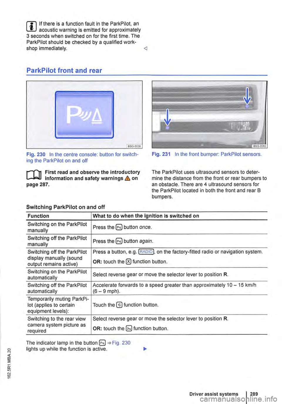
Fig. 230 In the centre console: button for switch-ing the ParkPilot on and off Fig. 231 In the front bumper: ParkPilot sensors.
r'l'11 First read and observe the Introductory Information and safety warnings & on page 287.
The Park Pilot uses ultrasound sensors to deter-mine the distance from the front or rear bumpers to an obstacle. There are 4 ultrasound sensors for the ParkPilot located in both the front and rear B bumpers.
Switching ParkPilot on and off
Function What to do when the Ignition is switched on
Switching on the ParkPilot Press button once. manually
Switching off the ParkPilot Press button again. manually
Switching off the ParkPilot Press a button, e.g. (RADIO!, on the factory-fitted radio or navigation system. display manually (sound OR: touch the 0 function button. output remains active)
Switching on the ParkPilot Select reverse gear or move the selector lever to position R. automatically
Switching off the ParkPilot Accelerate forwards to a speed greater than approximately 10-15 kmlh automatically (6-9 mph).
Temporarily muting ParkPi-lot (applies to certain Touch the@) function button. equipment levels):
Switching to the rear view Select reverse gear or move the selector lever to position R. camera system picture as OR: touch function button. required
The indicator lamp in the =:o Fig. 230 lights up while the function is active.
Driver assist systems 1289
Page 290 of 486
Special features of ParkPilot
• In some cases, the ParkPilot registers water and ice on the ultrasound sensors as an obstacle.
• The acoustic warning will become quieter after a few seconds if the distance remains the same. The volume will remain constant if the signal tone is continuous.
• The intermittent signal tone switches off auto-matically as soon as the vehicle moves away from an obstacle again. If the vehicle approaches the obstade again, the acoustic warning is switched on automatically.
• No acoustic signal is given in vehicles with a dual clutch gearbox DSG® if the selector lever is in position P.
ParkPilot signal tones and displays
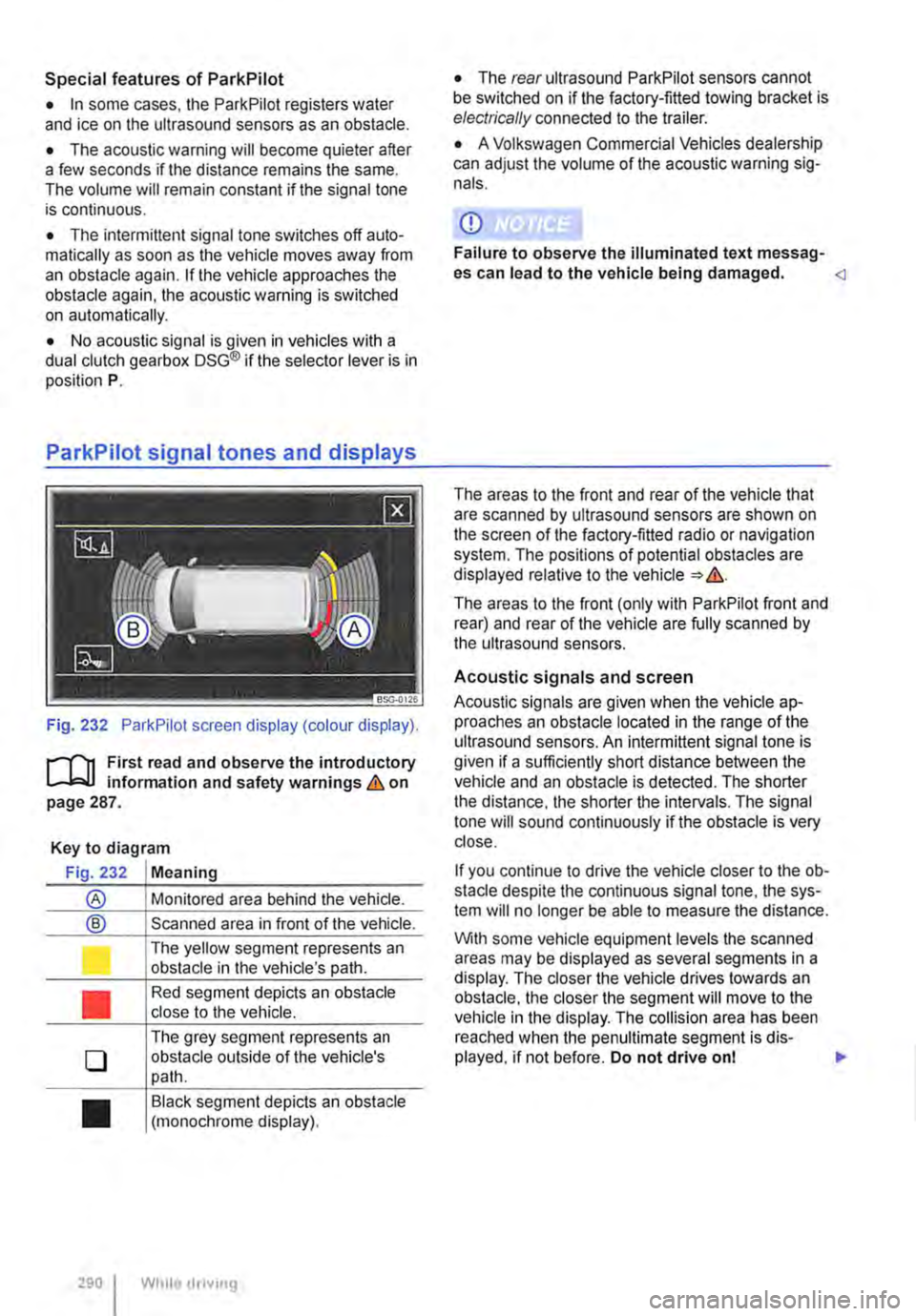
Fig. 232 ParkPilot screen display (colour display).
r--f"'n First read and observe the introductory L-.I=.U Information and safety warnings & on page 287.
Key to diagram
Fig. 232 Meaning
® Monitored area behind the vehide.
® Scanned area in front of the vehicle.
l J
•
0
•
290 I
The yellow segment represents an obstacle in the vehicle's path.
Red segment depicts an obstacle close to the vehicle.
The grey segment represents an obstacle outside of the vehicle's path.
Black segment depicts an obstacle (monochrome display).
While droving
• The rear ultrasound ParkPilot sensors cannot be switched on if the factory-fitted towing bracket is electrically connected to the trailer.
• A Volkswagen Commercial Vehicles dealership can adjust the volume of the acoustic warning sig-nals.
CD
Failure to observe the illuminated text messag-es can lead to the vehicle being damaged.
The areas to the front (only with ParkPilot front and rear) and rear of the vehicle are fully scanned by the ultrasound sensors.
Acoustic signals and screen
Acoustic signals are given when the vehicle ap-proaches an obstacle located in the range of the ultrasound sensors. An intermittent signal tone is given if a sufficiently short distance between the vehicle and an obstacle is detected. The shorter the distance, the shorter the intervals. The signal tone will sound continuously if the obstacle is very close.
If you continue to drive the vehide closer to the ob-sta de despite the continuous signal tone, the sys-tem will no longer be able to measure the distance.
With some vehicle equipment levels the scanned areas may be displayed as several segments in a display. The closer the vehicle drives lowards an obstacle, the closer the segment will move to the vehicle in the display. The collision area has been reached when the penultimate segment is dis-played, if not before. Do not drive onl .,..