VOLKSWAGEN TRANSPORTER 2012 Owners Manual
Manufacturer: VOLKSWAGEN, Model Year: 2012, Model line: TRANSPORTER, Model: VOLKSWAGEN TRANSPORTER 2012Pages: 486, PDF Size: 69.28 MB
Page 331 of 486
Windscreen heating
1111 First read and observe the introductory L.-J,::.U information and safety warnings & on page 322.
Windscreen heating helps to de-ice the
windscreen and only works when the en-
gine is running.
Switching on and off
Press the button ®in the centre console or the Climatronic to switch the windscreen heating on and off.
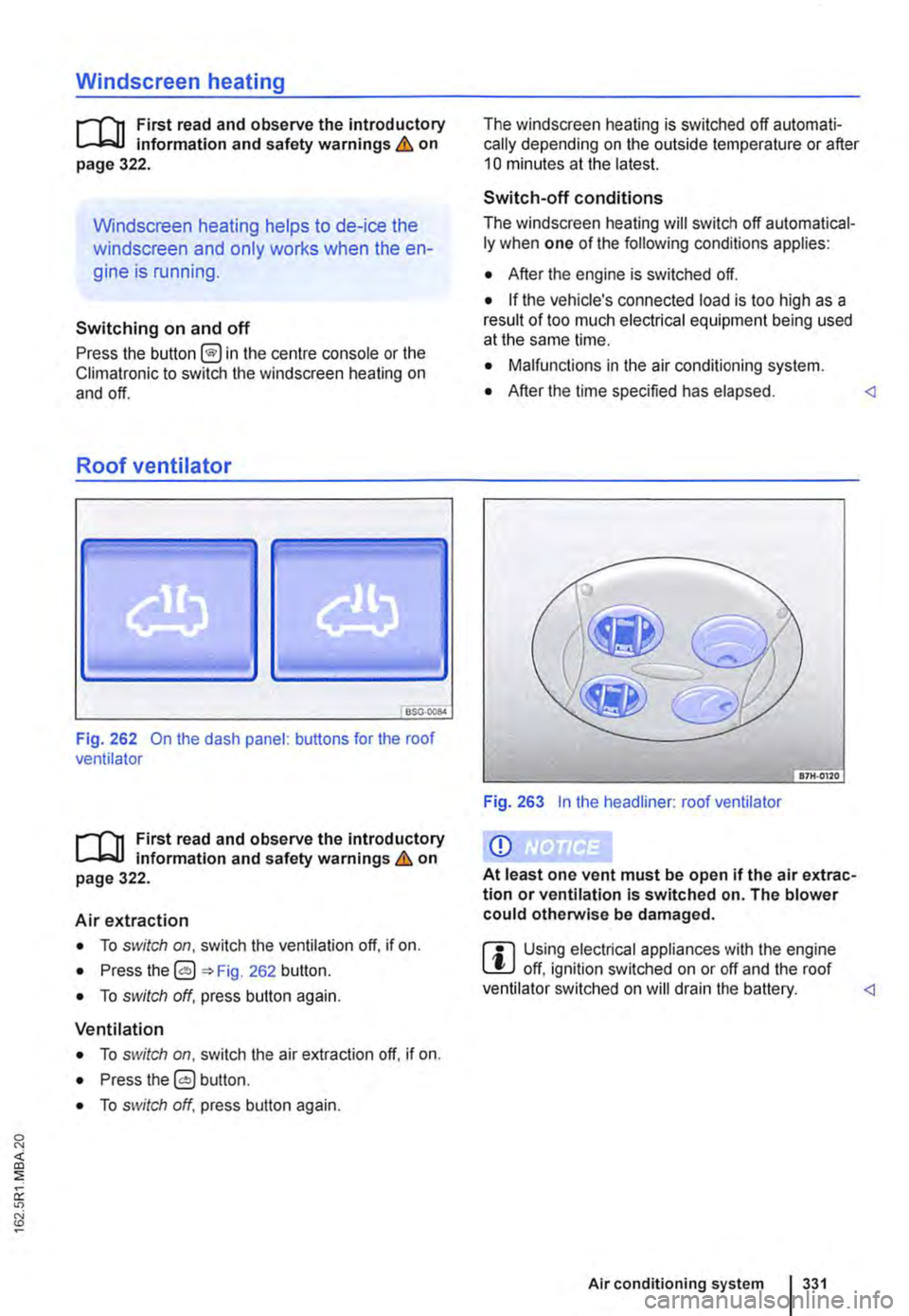
Roof ventilator
BS0-000<
Fig. 262 On the dash panel: buttons for the roof ventilator
1111 First read and observe the introductory L.-J,::.U Information and safety warnings & on page 322.
Air extraction
• To switch on, switch the ventilation off, if on.
• Press the 0 262 button.
• To switch off, press button again.
Ventilation
• To switch on, switch the air extraction off. if on.
• Press the 0 button.
• To switch off, press button again.
The windscreen heating is switched off automati-cally depending on the outside temperature or after 10 minutes at the latest.
Switch-off conditions
The windscreen heating will switch off automatical-ly when one of the following conditions applies:
• After the engine is switched off.
• If the vehicle's connected load is too high as a result of too much electrical equipment being used at the same lime.
• Malfunctions in the air conditioning system.
• After the time specified has elapsed.
Q)
At least one vent must be open if the air extrac-tion or ventilation Is switched on. The blower could otherwise be damaged.
ffi Using electrical appliances with the engine L!J off, ignition switched on or off and the roof ventilator switched on will drain the battery.
Page 332 of 486
![VOLKSWAGEN TRANSPORTER 2012 Owners Manual Supplementary heaters (auxiliary air heater or auxiliary
coolant heater)
[Q] Introduction
This chapter contains information on the following subjects:
Controls . . . . . . . . . . . . . . . . . . VOLKSWAGEN TRANSPORTER 2012 Owners Manual Supplementary heaters (auxiliary air heater or auxiliary
coolant heater)
[Q] Introduction
This chapter contains information on the following subjects:
Controls . . . . . . . . . . . . . . . . . .](/img/18/55785/w960_55785-331.png)
Supplementary heaters (auxiliary air heater or auxiliary
coolant heater)
[Q] Introduction
This chapter contains information on the following subjects:
Controls . . . . . . . . . . . . . . . . . . . . . . . . . . . . . . . 333
Switching the supplementary heating system on and off . . . . . . . . . . . . . . . . . . . . . . . . 334
Remote control . . . . . . . . . . . . . . . . . 335
Programming the supplementary heating system . . . . . . . . . . . . . . . . . . . . . . 338 Switching the child proof lock on and off . . . . . 339
Operation . . . . . . . . . . . . . . . . . . . . . . . . 339
The supplementary heating system is supplied with fuel from the vehicle fuel tank and can be used when the vehicle is in motion or stationary. Electri-cal power is supplied by the vehicle battery.
The auxiliary air heater runs in air recirculation mode and heats the vehicle interior. it has sepa-rate vents in the passenger compartment =>Fig. 265.
The auxiliary coolant heater heats the heating circuit. Heat is guided into the vehicle interior via the vents for the heating or air conditioning system. With the auxiliary coolant heater, it is possible to switch between heating and ventilating.
Additional information and warnings:
• Supplementary heater in the California =>page 192
• Filling the tank =>page 340
• Battery =>page 362
Swallowing batteries with a diameter of 20 mm or other lithium batteries can result in severe or even fatal injuries within a very short period of time.
• Always keep the vehicle key, key ring with batteries, spare batteries, round cells and other batteries that are larger than 20 mm out of the reach of children.
332 I While driving
• Call for medical help immediately you pect that someone has swallowed a batte
A WARNING
The fumes from the supplementary heating system contain carbon monoxide, which is an odourless and colourless poisonous gas. Carbon monoxide can cause people to lose consciousness. lt can also cause death.
• Never start or run the supplementary heat-ing system In unventllated or closed rooms.
• Never program the supplementary heating system so that Is switched on and run In un-ventilated or enclosed areas.
A WARNING
Parts of the exhaust system of the supple-mentary heating system become very hot. This can cause fires.
• Park the vehicle so that no part of the ex-haust system can come Into contact with any Inflammable material underneath the vehicle, e.g. dry grass.
Q)
Do not place any food, medicine or any other temperature-sensitive items in front of the vents. Heat-sensitive food, medicine and other items could be either damaged or rendered useless.
m After starting the engine with a discharged W vehicle battery, or after the battery has been changed, system settings (time, date, personal convenience settings and programming) may have been changed or deleted. Check and correct the settings as necessary once the vehicle battery has been sufficiently charged.
Page 333 of 486
Controls
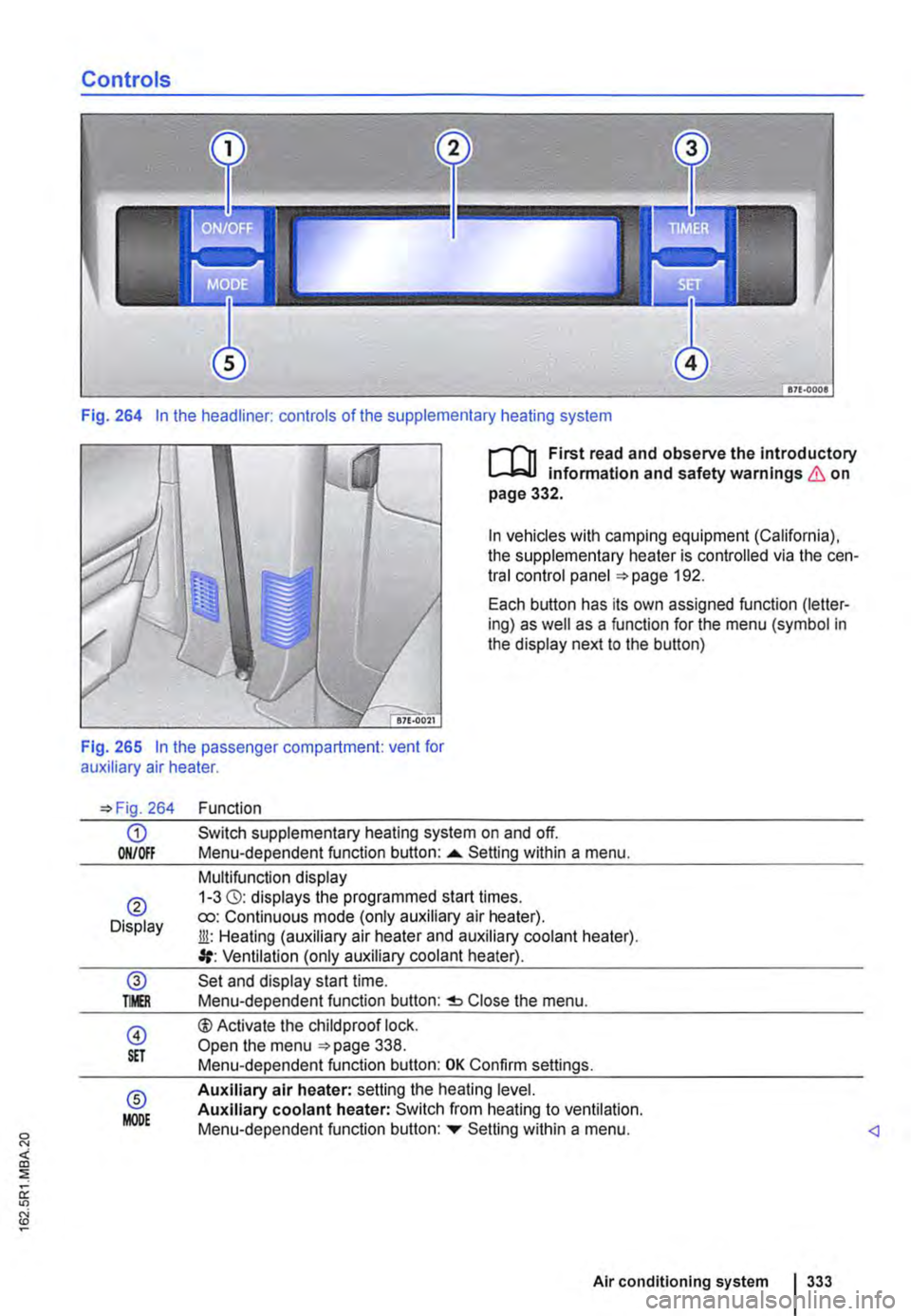
Fig. 264 In the headliner: controls of the supplementary heating system
I""""T'n First read and observe the introductory l.-..1=.1.1 infonmatlon and safety warnings & on page 332.
In vehicles with camping equipment (California), the supplementary heater is controlled via the cen-tral control panel 192.
Each button has its own assigned function (letter-ing) as well as a function for the menu (symbol in the display next to the button)
Fig. 265 In the passenger compartment: vent for auxiliary air heater.
264
G) ON/Off
® Display
@ TMR
@ S£T
® MODE
Function
Switch supplementary heating system on and off. Menu-dependent function button: ......_ Setting within a menu.
Multifunction display 1-3 (3): displays the programmed start times. ro: Continuous mode (only auxiliary air heater). Jli: Heating (auxiliary air heater and auxiliary coolant heater). Ventilation (only auxiliary coolant heater).
Set and display start time. Menu-dependent function button: Close the menu.
®Activate the child proof lock. Open the menu 338. Menu-dependent function button: OK Confirm settings.
Auxiliary air heater: setting the heating level. Auxiliary coolant heater: Switch from heating to ventilation. Menu-dependent function button: ...,. Setting within a menu.
Air conditioning system I 333
Page 334 of 486
Switching the supplementary heating system on and off
r-Y'n First read and observe the introductory L-J.:.I.I information and safety warnings & on page 332.
In vehicles with camping equipment (California), the supplementary heater is controlled via the cen-tral control panel =>page 192.
Switching on the supplementary heating sys-tem:
Manually with button [011/0IF) in the roof dis-ON/OFF play.
l/i Manually with the remote control key.
Automatically with a programmed and ac-tivated switch-on time.
Switching off the supplementary heating sys-tem:
ON/OFF Manually with the function button =>Fig. 264 CD in the roof display.
Off Manually with the remote control key.
Automatically after the set operating dura-tion has elapsed.
Only if the vehicle has an auxiliary coolant heater Automatically when the indicator lamp lights (fuel gauge) =>page 340.
Automatically if the charge level of the ad-ditional battery is too low =>page 362.
Setting the operating duration (when the ignition is switched off)
The default setting for the operating duration is 30 minutes. You can set the operating duration be-tween 10 and 120 minutes.
• Press any button on the roof display to activate the roof display.
• Only if the vehicle has an auxiliary coolant heater: Press the button to set the operating mode.
• Press the@ button.
• Press the button@) to set the operating dura-tion.
334 I While driv1ng
• Press the function button ....,. or T until the re-quired operating duration is displayed.
• Press button@) again to confirm the operating duration.
• Only for auxiliary air heater: press the func-tion button ....,. or ... as often as necessary until the desired heating level is displayed.
The supplementary heating system has been switched on. The operatin_lLduration is counted backwards. Press to switch off the sup-plementary heating system prematurely.
Continuous mode eo (only for auxiliary air heater, with the ignition switched off)
Press any button on the roof display to activate the roof display.
Press the@) button.
Press the @) button.
Press the function button ....,. or ... as often as nec-essary until Heating eo is displayed.
Press button @)to confirm the setting.
Press the function button ....,. or T as often as nec-essary until the required temperature level is dis-played.
Press button @)again to confirm the temperature.
Things to note
The supplementary heating system runs on for a short time after it is switched off in order to cool the heating unit (switch-off delay). The exhaust gases in the system can also be emitted.
Switch-off delay for the auxiliary heater
If the ignition is switched off while the auxiliary wa-ter heater is on, the selected function continues being performed for a maximum of 10 minutes. The set switch-off delay is shown on the display.
Each time button is pressed, the switch-off delay is reduced by one minute.
Page 335 of 486
Remote control
B
BSG·OOS3
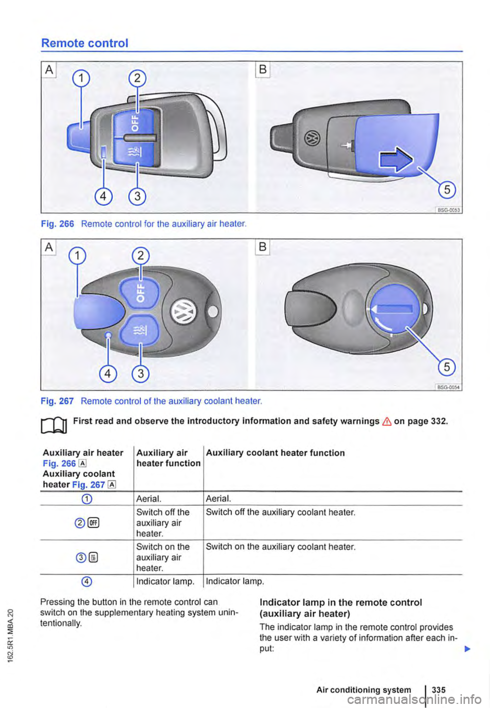
Fig. 266 Remote control for the auxiliary air heater.
A
BSG-0054
Fig. 267 Remote control of the auxiliary coolant heater.
ru First read and observe the introductory Information and safety warnings & on page 332.
Auxiliary air heater Auxiliary air Auxiliary coolant heater function Fig. heater function Auxiliary coolant heater Fig. 267
CD Aerial. Aerial.
Switch off the Switch off the auxiliary coolant heater.
0@) auxiliary air heater.
Switch on the Switch on the auxiliary coolant heater.
0@ auxiliary air heater.
@) Indicator lamp. Indicator lamp.
Pressing the button in the remote control can switch on the supplementary heating system unin-tentionally.
Indicator lamp in the remote control (auxiliary air heater)
The indicator lamp in the remote control provides the user with a variety of information after each in-put: 1>-
Air conditioning system 335
Page 336 of 486
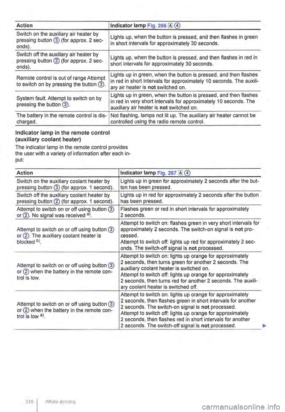
Action I Indicator lamp Fig. 266
Switch on the auxiliary air heater by pressing button @ (for approx. 2 sec-onds).
Switch off the auxiliary air heater by pressing button ® (for approx. 2 sec-onds).
Lights up, when the button is pressed, and then flashes in green in short intervals for approximately 30 seconds.
Lights up, when the button is pressed, and then flashes in red in short intervals for approximately 30 seconds.
Lights up in green, when the button is pressed, and then flashes Remote control is out of range Attempt in red in short intervals for approximately 10 seconds. The auxili-to switch on by pressing the button @. ary air heater is not switched on.
System fault. Attempt to switch on by pressing the button @.
Lights up in green, when the button is pressed, and then flashes in red in very short intervals for approximately 10 seconds. The auxiliary air heater is not switched on.
The battery in the remote control is dis-charged. Not flashing, lamps not lit up. The auxiliary air heater cannot be controlled using the radio remote control.
Indicator lamp in the remote control (auxiliary coolant heater)
The indicator lamp in the remote control provides the user with a variety of information after each in-put:
Action Indicator lamp Fig. 267
Switch on the auxiliary coolant heater by Lights up in green for approximately 2 seconds after the but-pressing button@ (for approx. 1 second). ton has been pressed.
Switch off the auxiliary coolant heater by Lights up in red for approximately 2 seconds after the button pressing button® (for approx. 1 second). has been pressed.
Attempt to switch on or off using button @ Flashes green or red in short intervals for approximately or@. No signal was received a). 2 seconds.
Attempt to switch on: flashes green in very short intervals for Attempt to switch on or off using button@ approximately 2 seconds. The switch-on signal is not pro-or@. The auxiliary coolant heater is cessed. blocked b). Attempt to switch off: lights up red for approximately 2 sec-onds. The switch-off signal is not processed.
Attempt to switch on: lights up orange for approximately
Attempt to switch on or off using button@ 2 seconds, then turns green for another 2 seconds. The
or® when the battery in the remote con-auxiliary coolant heater is switched on. Attempt to switch off: lights up orange for approximately trot is low. 2 seconds, then turns red for another 2 seconds. The auxili-ary coolant heater is switched off.
Attempt to switch on: lights up orange for approximately
Attempt to switch on or off using button @ 2 seconds, then flashes green in short intervals for another
or® when the battery in the remote con-2 seconds. The switch-on signal is not processed.
trot is low a). Attempt to switch off: lights up orange for approximately 2 seconds, then flashes red in short intervals for another 2 seconds. The switch-off signal is not processed.
336 I While droving
Page 337 of 486
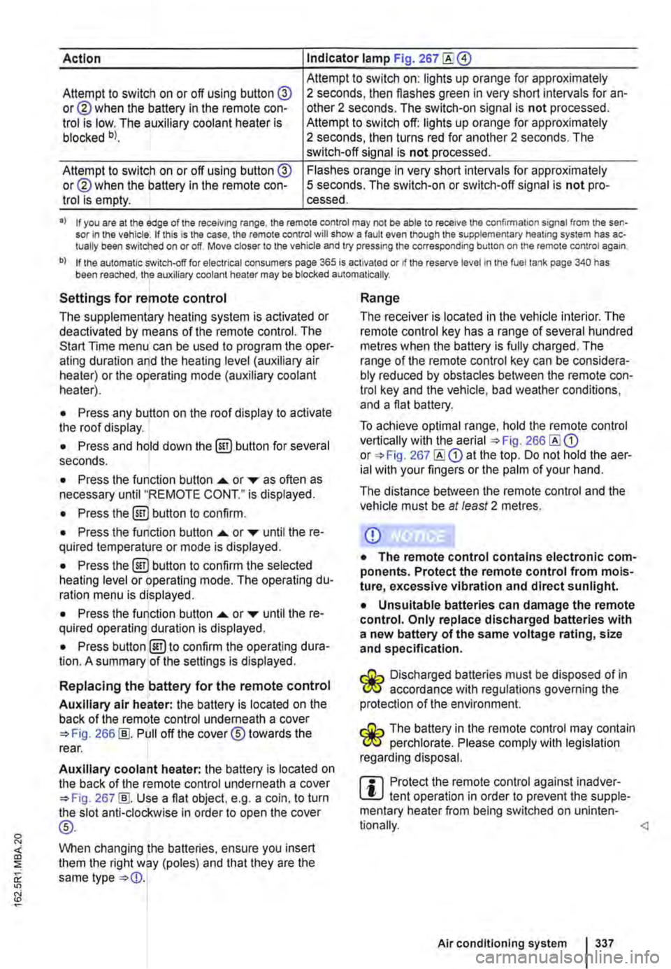
Action Indicator lamp Fig. 267
Attempt to switch on: lights up orange for approximately Attempt to switch on or off using button @ or@ when the battery in the remote con-trol is low. The auxiliary coolant heater is blocked bl.
2 seconds, then flashes green in very short intervals for an-other 2 seconds. The switch-on signal is not processed. Attempt to switch off: lights up orange for approximately 2 seconds, then turns red for another 2 seconds. The switch-off signal is not processed.
Attempt to switch on or off using button @ or@ when the battery in the remote con-trol is empty.
Flashes orange in very short intervals for approximately 5 seconds. The switch-on or switch-off signal is not pro-cessed.
•> If you are at the edge of the receiving range, the remote control may not be able to receive the confirmation signal from the sen-sor in the vehicle. If this is the case, the remote control will show a fault even though the supplementary heating system has ac-tually been switched on or off. Move closer to the vehicle and try pressing the corresponding button on the remote control again.
b) If the automatic switch-off for electrical consumers page 365 is activated or if the reserve level in lhe fuel tank page 340 has been reached, the auxiliary coolant heater may be blocked automatically.
Settings for remote control
The supplementary heating system is activated or deactivated by means of the remote control. The Start Time menu can be used to program the oper-ating duration and the heating level (auxiliary air heater) or the operating mode (auxiliary coolant heater).
• Press any button on the roof display to activate the roof display.
• Press and hold down the (ill) button for several seconds.
• Press the function button ...... or ,... as often as necessary until "REMOTE CONT." is displayed.
• Press the (ill) button to confirm.
• Press the function button ...... or ,... until the re-quired temperature or mode is displayed.
• Press the (ill) button to confirm the selected heating level or operating mode. The operating du-ration menu is displayed.
• Press the function button ...... or ,... until the re-quired operating duration is displayed.
• Press button @)to confirm the operating dura-tion. A summary of the settings is displayed.
Replacing the battery for the remote control
Auxiliary air heater: the battery is located on the back of the remote control underneath a cover 266 [ID. Pull off the cover® towards the rear.
Auxiliary coolant heater: the battery is located on the back of the remote control underneath a cover 267 [ID. Use a flat object, e.g. a coin, to turn the slot anti-clockwise in order to open the cover
®-
When changing the batteries, ensure you insert them the right way (poles) and that they are the same type
Range
The receiver is located in the vehicle interior. The remote control key has a range of several hundred metres when the battery is fully charged. The range of the remote control key can be considera-bly reduced by obstacles between the remote con-trol key and the vehicle, bad weather conditions, and a flat battery.
To achieve optimal range, hold the remote control vertically with the aerial 266 or 267 at the top. Do not hold the aer-ial with your fingers or the palm of your hand.
The distance between the remote control and the vehicle must be at least 2 metres.
CD
• The remote control contains electronic com-ponents. Protect the remote control from mois-ture, excessive vibration and direct sunlight.
• Unsuitable batteries can damage the remote control. Only replace discharged batteries with a new battery of the same voltage rating, size and specification.
Discharged batteries must be disposed of in W accordance with regulations governing the protection of the environment.
The battery in the remote control may contain W perchlorate. Please comply with legislation regarding disposal.
m Protect the remote control against inadver-L!.J tent operation in order to prevent the supple-mentary heater from being switched on uninten-
Air conditioning system I 337
Page 338 of 486
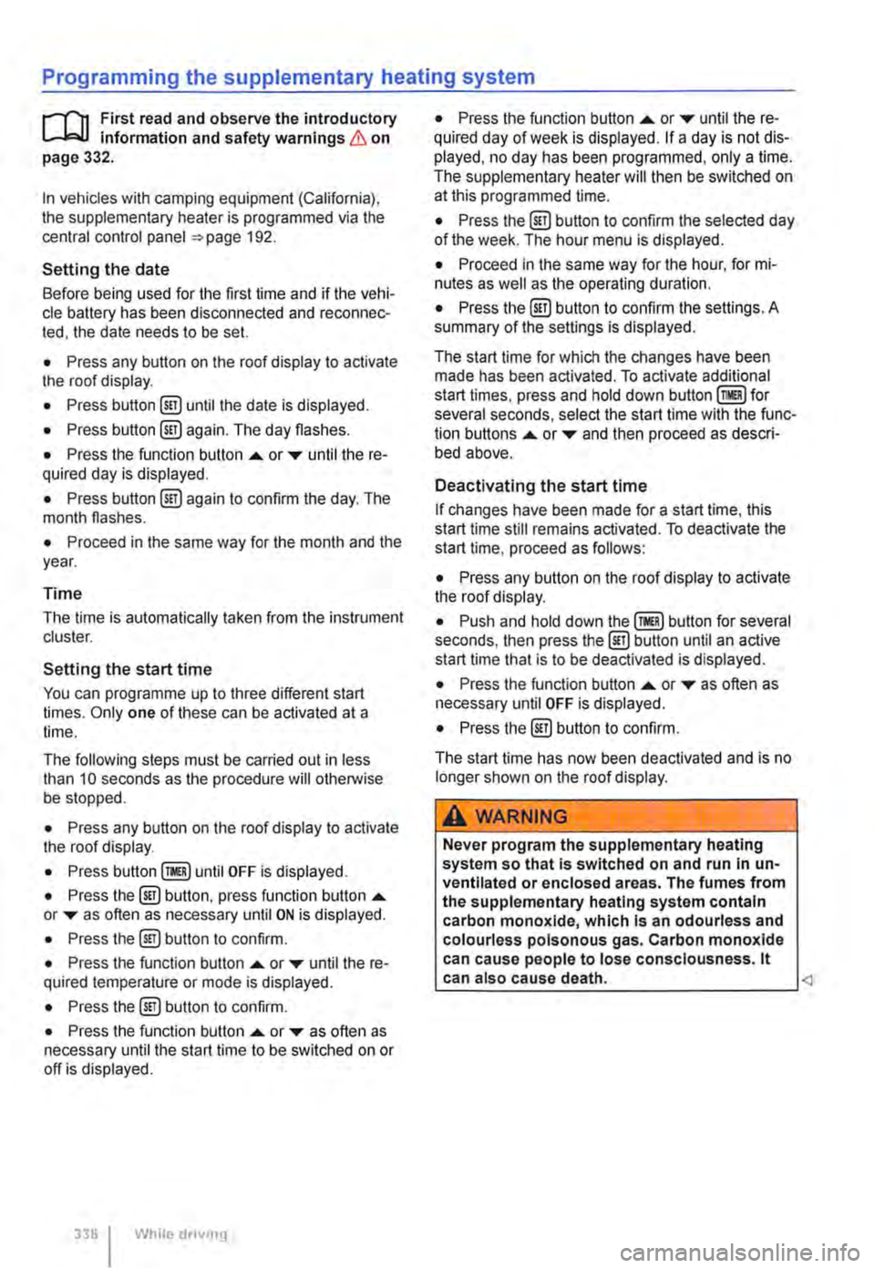
Programming the supplementary heating system
r('n First read and observe the introductory L-Wl Information and safety warnings & on page 332.
In vehicles with camping equipment (California), the supplementary heater is programmed via the central control panel =>page 192.
Setting the date
Before being used for the first time and if the vehi-cle battery has been disconnected and reconnec-ted, the date needs to be set.
• Press any button on the roof display to activate the roof display.
• Press button @!) until the date is displayed.
• Press button @!) again. The day flashes.
• Press the function button .... or T until the re-quired day is displayed.
• Press button @!) again to confirm the day. The month flashes.
• Proceed in the same way for the month and the year.
Time
The time is automatically taken from the instrument cluster.
Setting the start time
You can programme up to three different start times. Only one of these can be activated at a time.
The following steps must be carried out in less than 10 seconds as the procedure will otherwise be stopped.
• Press any button on the roof display to activate the roof display.
• Press until OFF is displayed.
• Press the @) button, press function button .... or T as often as necessary until ON is displayed.
• Press the@) button to confirm.
• Press the function button .... or T until the re-quired temperature or mode is displayed.
• Press the @!) button to confirm.
• Press the function button .... or T as often as necessary until the start time to be switched on or off is displayed.
338 I While dnvmg
• Press the function button .... or T until the re-quired day of week is displayed. If a day is not dis-played, no day has been programmed, only a time. The supplementary heater will then be switched on at this programmed time.
• Press the @) button to confirm the selected day of the week. The hour menu is displayed.
• Proceed in the same way for the hour, for mi-nutes as well as the operating duration.
• Press the @) button to confirm the settings. A summary of the settings is displayed.
The start time for which the changes have been made has been activated. To activate additional start times, press and hold down for several seconds, select the start time with the func-tion buttons .... or T and then proceed as descri-bed above.
Deactivating the start time
If changes have been made for a start time, this start time still remains activated. To deactivate the start time, proceed as follows:
• Press any button on the roof display to activate the roof display.
• Push and hold down button for several seconds, then press the@) button until an active start time that is to be deactivated is displayed.
• Press the function button .... or T as often as necessary until OFF is displayed.
• Press the @) button to confirm.
The start time has now been deactivated and is no longer shown on the roof display.
A WARNING
Never program the supplementary heating system so that Is switched on and run In un-ventllated or enclosed areas. The fumes from the supplementary heating system contain carbon monoxide, which Is an odourless and colourless poisonous gas. Carbon monoxide can cause people to lose consciousness. lt can also cause death.
Page 339 of 486
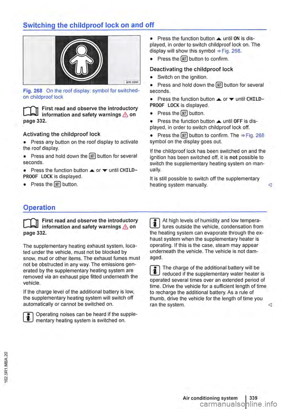
Switching the childproof lock on and off
B7f·0201
Fig. 268 On the roof display: symbol for switched-on child proof lock
r-T'n First read and observe the introductory L-.bU information and safety warnings & on page 332.
Activating the childproof lock
• Press any button on the roof display to activate the roof display.
• Press and hold down the @) button for several seconds.
• Press the function button .... or ..-until CHILD-PROOF LOCK is displayed.
• Press the@) button.
Operation
r-T'n First read and observe the introductory L-.bU information and safety warnings & on page 332.
The supplementary heating exhaust system, loca-ted under the vehicle, must not be blocked by snow, mud or other items. The exhaust fumes must not be obstructed in any way. The emissions gen-erated by the supplementary heating system are removed via an exhaust pipe fitted underneath the vehicle.
If the charge level of the additional battery is low, the supplementary heating system will switch off automatically or cannot be switched on.
m Operating noises can be heard if the supple-l!J mentary heating system is switched on.
• Press the function button .... until ON is dis-played, in order to switch child proof lock on. The display will show this symbol =>Fig. 268.
• Press the @] button to confirm.
Deactivating the childproof lock
• Switch on the ignition.
• Press and hold down the@] button for several seconds.
• Press the function button....._ or..-until CHILD-PROOF LOCK is displayed.
• Press the@) button.
• Press the function button .... until OFF is dis-played. in order to switch child proof lock off.
• Press the@) button to confirm. The =>Fig. 268 symbol on the display goes out.
If the child proof lock has been switched on and the ignition has been switched off, it is not possible to switch the supplementary heating system on man-ually.
lt is still possible to switch off the supplementary heating system manually.
r::l The charge of the additional battery will be W reduced if the supplementary water heater is operated several times over an extended period of time. Drive the vehicle for a sufficient length of time to recharge the additional battery. As a rule of thumb, drive the vehicle for the length of time you ran the system.
Page 340 of 486
At the filling station
Filling the tank
o:n Introduction
This chapter contains information on the following subjects:
Indicator lamps and fuel gauge . . . . . . . . . . . . 341
Filling the tank with petrol or diesel . . . . . . . . . 342
Capacities . . . . . . . . . . . 343
Checks when filling the tank . . . . . . . . . . . . . . . 343
The fuel cap is located at the left-hand side of the vehicle.
Additional information and warnings:
• Exterior views 5
• Fuel 343
• Preparation for working in the engine ccmpart-ment page 350
A WARNING
Filling the tank incorrectly and incorrect han-dling of fuel can cause explosions, fire, seri-ous burns and other injuries.
• Always ensure that the tank cap is proper-ly closed, to prevent the evaporation and spillage of fuel.
• Fuel is highly explosive and inflammable and can cause serious burns and other inju-ries.
• Fuel can spill out if the engine is not switched off or the filler nozzle is not fully in-serted into the fuel filler neck when filling the tank. This could cause fire, explosions, seri-ous burns and other Injuries.
• When refilling with fuel, the engine , sup-plementary heating system(=> page 332) and the ignition must be switched off for security reasons.
• When filling the tank, always switch off your mobile telephone and two-way radio or any other radio equipment. Electromagnetic radiation can generate sparks which can in turn start a fire.
• Never get back into the vehicle while fill-ing the tank. If in exceptional cases you have to enter the vehicle, close the door and touch a metal object before touching the filler noz-zle again. This will remove any electrostatic
340 I While driving
A WARNING (Continued)
charge from you. Failure to do so could gen-erate a spark. Sparks can cause a fire when filling the tank.
• Never refuel or fill a spare canister near open flames, sparks or smouldering Items, e.g. cigarettes.
• Electrostatic discharge and electromag-netic radiation must be avoided when filling the tank.
• Follow all applicable safety information provided by the filling station when filling the tank.
• Never spill fuel in the vehicle or In the lug-gage compartment
A WARNING
For safety reasons, Volkswagen Commercial Vehicles does not recommend carrying a spare fuel canister In the vehicle. Fuel can spill out of the full or empty canister and catch fire, especially In the event of an acci-dent. This could cause explosions, fire and injuries.
• If, In exceptional circumstances, you have to transport a spare fuel canister, please note the following:
-When refilling never place the canister In or on top of the vehicle, for example In the luggage compartment or on the tall-gate. There may be an electrostatic charge during refilling causing the fuel fumes to Ignite.
-Always place the spare fuel canister on the ground.
-When filling a spare fuel canister, place the filler nozzle as far as possible Into the filler opening.
-If the spare fuel canister Is made of met-al, the filler nozzle must have constant contact with the canister In order to avoid static charging.
-Please follow all legislation concerning the use, stowage and transport of a spare fuel canister.