start stop button VOLKSWAGEN TRANSPORTER 2013 User Guide
[x] Cancel search | Manufacturer: VOLKSWAGEN, Model Year: 2013, Model line: TRANSPORTER, Model: VOLKSWAGEN TRANSPORTER 2013Pages: 486, PDF Size: 69.28 MB
Page 271 of 486
A WARNING (Continued)
• If the brake warning lamp ID does not go out, or if it lights up when driving, the brake fluid level in the reservoir is too low or there is a fault in the brake system. Stop the vehi-cle Immediately and seek expert assistance 277, Brake fluid.
• If the brake warning lamp@ lights up to-gether with the ABS indicator lamp S, the control function of the ABS may have failed. This can cause the rear wheels to lock quick-ly when you brake. Locked rear wheels can lead to a loss of control of the vehicle. If pos-sible, reduce your speed and drive carefully at low speed to the nearest qualified work-shop in order to have the brake system tes-ted. Avoid sudden braking and driving ma-noeuvres on the way.
• The ABS Is not functioning correctly if the ABS indicator lampS does not go out or comes on while the vehicle is in motion. The
Handbrake
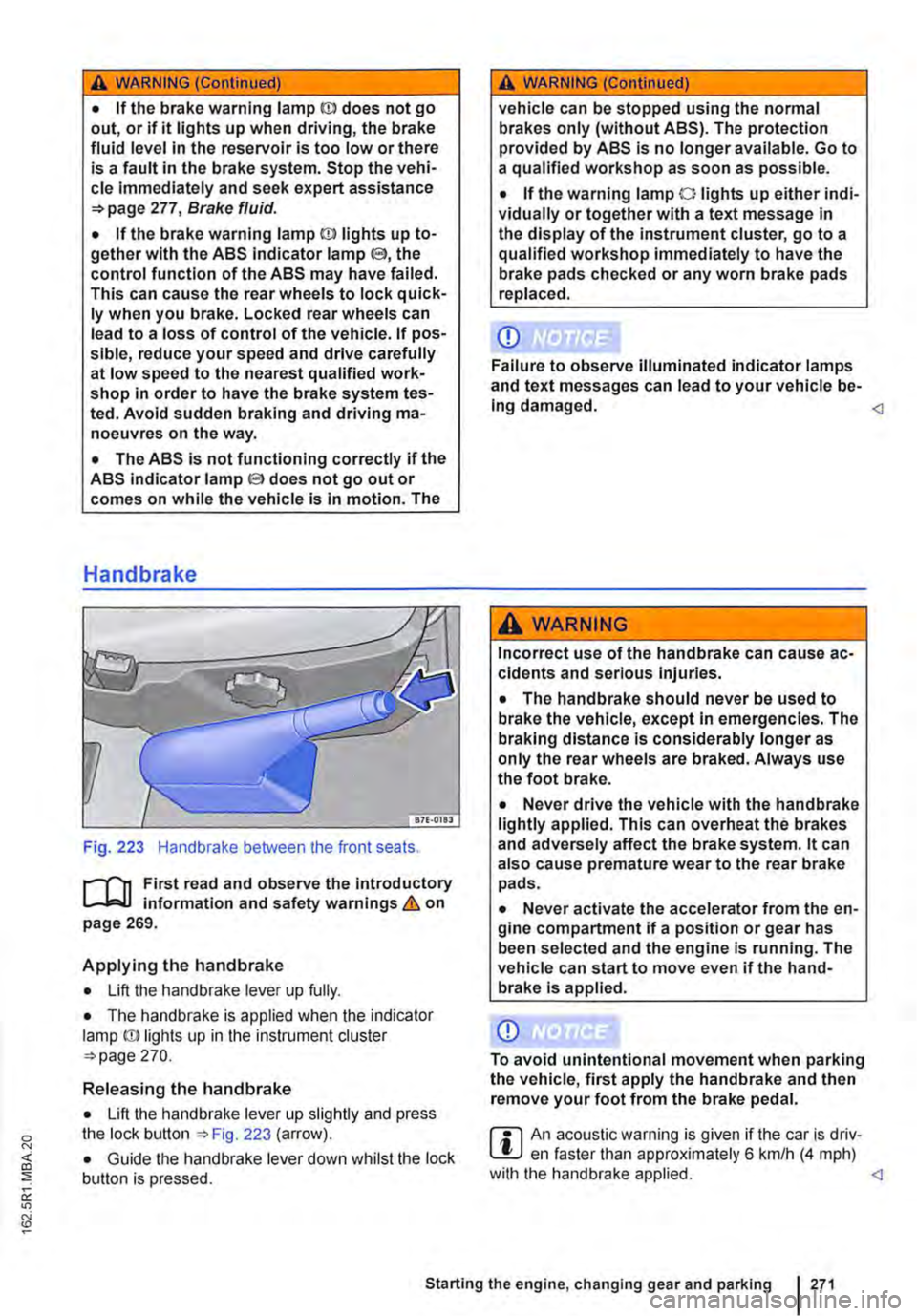
Fig. 223 Handbrake between the front seats.
r--fl1 First read and observe the introductory L-J,::.IJ information and safety warnings & on page 269.
Applying the handbrake
• Lift the handbrake lever up fully.
• The handbrake is applied when the indicator lamp ID lights up in the instrument cluster =-page 270.
Releasing the handbrake
• Lift the handbrake lever up slightly and press the lock button ::.Fig. 223 (arrow).
• Guide the handbrake lever down whilst the lock button is pressed.
A WARNING (Continued)
vehicle can be stopped using the normal brakes only (without ABS). The protection provided by ABS is no longer available. Go to a qualified workshop as soon as possible.
• If the warning lamp 0 lights up either indi-vidually or together with a text message in the display of the instrument cluster, go to a qualified workshop immediately to have the brake pads checked or any worn brake pads replaced.
CD
Failure to observe illuminated indicator lamps and text messages can lead to your vehicle be-Ing damaged.
Incorrect use of the handbrake can cause ac-cidents and serious Injuries.
• The handbrake should never be used to brake the vehicle, except in emergencies. The braking distance is considerably longer as only the rear wheels are braked. Always use the foot brake.
• Never drive the vehicle with the handbrake lightly applied. This can overheat the brakes and adversely affect the brake system. lt can also cause premature wear to the rear brake pads.
• Never activate the accelerator from the en-gine compartment if a position or gear has been selected and the engine is running. The vehicle can start to move even if the hand-brake Is applied.
CD
To avoid unintentional movement when parking the vehicle, first apply the handbrake and then remove your foot from the brake pedal.
r::l An acoustic warning is given if the car is driv-L.!:.J en faster than approximately 6 km/h (4 mph) with the handbrake applied.
Page 283 of 486
A WARNING
Failure to observe illuminated warning lamps and text messages can lead to your vehicle breaking down in traffic, and can cause acci-dent and serious injury.
• Never ignore any illuminated warning lamps or text messages.
Start/stop system
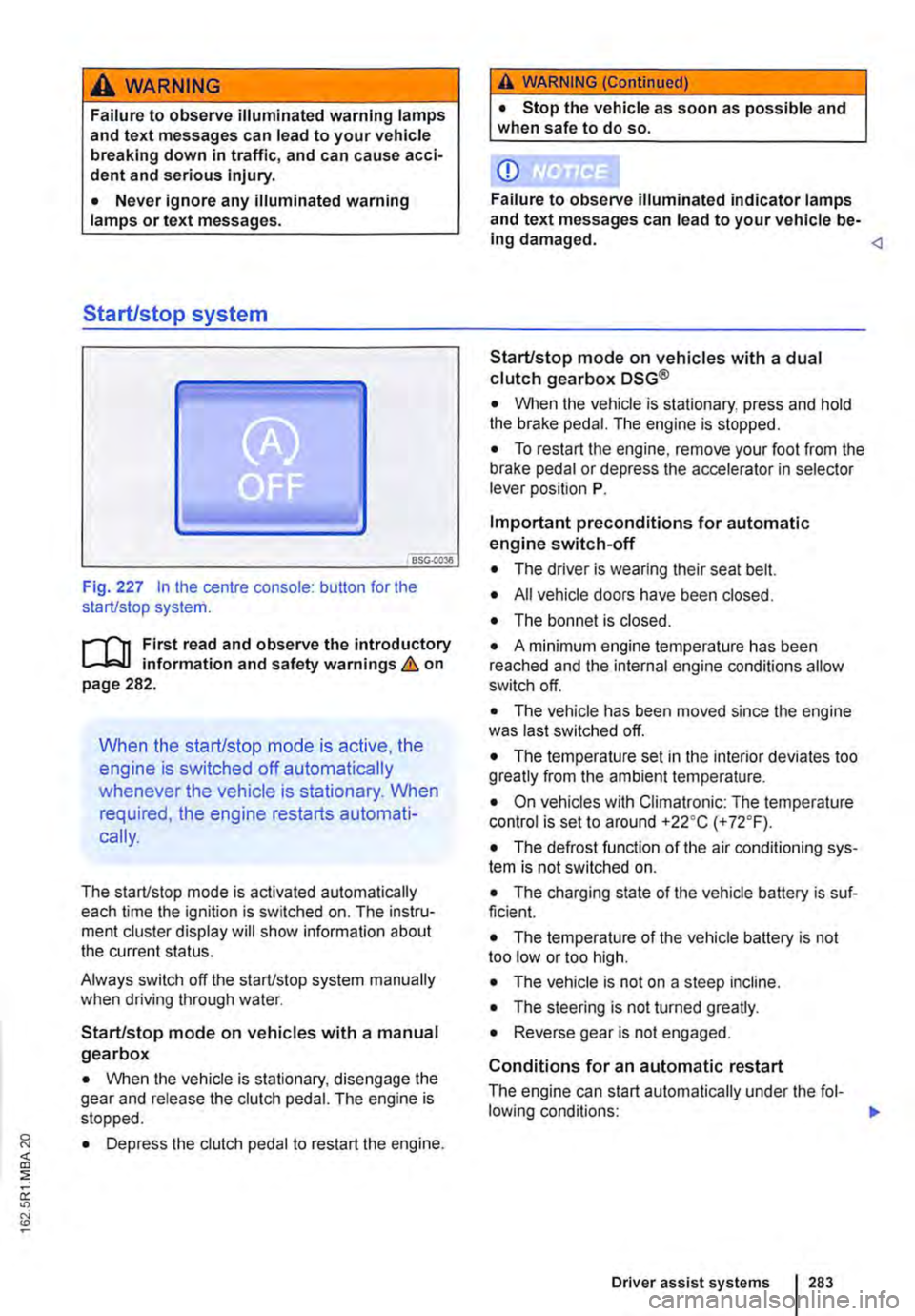
Fig. 227 In the centre console: button for the start/stop system.
r--flt First read and observe the introductory l-J,::JJ information and safety warnings & on page 282.
When the start/stop mode is active, the
engine is switched off automatically
whenever the vehicle is stationary. When
required, the engine restarts automati-
cally.
The start/stop mode is activated automatically each time the ignition is switched on. The instru-ment cluster display will show information about the current status.
Always switch off the start/stop system manually when driving through water.
Start/stop mode on vehicles with a manual gearbox
• When the vehicle is stationary, disengage the gear and release the clutch pedal. The engine is stopped.
• Depress the clutch pedal to restart the engine.
A WARNING (Continued)
• Stop the vehicle as soon as possible and when safe to do so.
CD
Failure to observe illuminated indicator lamps and text messages can lead to your vehicle be-ing damaged.
• When the vehicle is stationary, press and hold the brake pedal. The engine is stopped.
• To restart the engine, remove your foot from the brake pedal or depress the accelerator in selector lever position P.
Important preconditions for automatic engine switch-off
• The driver is wearing their seat belt.
• All vehicle doors have been closed.
• The bonnet is closed.
• A minimum engine temperature has been reached and the internal engine conditions allow switch off.
• The vehicle has been moved since the engine was last switched off.
• The temperature set in the interior deviates too greatly from the ambient temperature.
• On vehicles with Climatronic: The temperature control is set to around +22oC (+ 72°F).
• The defrost function of the air conditioning sys-tem is not switched on.
• The charging state of the vehicle battery is suf-ficient.
• The temperature of the vehicle battery is not too low or too high.
• The vehicle is not on a steep incline.
• The steering is not turned greatly.
• Reverse gear is not engaged.
Conditions for an automatic restart
The engine can start automatically under the fol-lowing conditions: IIJ>
Driver assist systems 283
Page 284 of 486
• On vehicles with Climatronic: if the temperature inside the vehicle substantially increases or de-creases.
• When the vehicle starts rolling or brake support is required.
• If the voltage of the vehicle battery falls.
Conditions that necessitate a manual key start
The engine has to be started manually with the ve-hicle key in the following conditions:
• If the driver unfastens their seat belt.
• If a vehicle door is opened.
• If the bonnet is opened.
Switching the start/stop system on and off manually
• Press the @ button in the centre console 227.
• If the start/stop system has been deactivated, the indicator lamp in the button lights up.
The engine will start immediately if the vehicle Is In stop mode when the system is switched off man-ually with the @ button.
Hill Hold Assist
r--T'n First read and observe the Introductory L-I=JJ information and safety warnings & on page 282.
A WARNING
The brake servo and the power steering will not function If the engine Is switched off.
• Never allow the vehicle to roll if the engine is switched off.
• The start/stop system must be switched off if work Is to be carried out In the engine compartment.
CD
If the start/stop system Is used in very high outside temperatures over a long period, the vehicle battery can be damaged.
m In some cases. it will be necessary to restart L!J the engine manually with the vehicle key. Fol-low any corresponding messages on the instru-ment cluster display.
m At low speeds, the engine can be started L!J again if it has stalled by immediately pressing the clutch pedal.
holds the vehicle when pulling away on
an incline.
The Hill Hold Assist function is automatically activated if the following conditions are met
Points 1 to 3 must be fulfilled at the same time·
Manual gearbox DSG® dual clutch gearbox
1. On an incline, the stationary vehicle must be held in position with the footbrake until the vehicle starts moving.
2. The engine is running smoothly.
3. The driver door is closed.
4. Fully depress the clutch pedal and move the gear stick to the first gear position if you want to The driving mode R, D or S has been selected. drive forwards up a hill or to the R position if you want to reverse up a hill.
In order to start moving, remove your foot from To start moving, remove your foot from the brake the brake pedal, then simultaneously release the pedal and press the accelerator immediately. clutch pedal (the clutch engages) and press the The brake will gradually be released as the accelerator. The brake will gradually be re-vehicle pulls away. leased as the clutch Is engaged.
284 I While driving
Page 285 of 486
The Hill Hold Assist function will be deactivated immediately:
Manual gearbox I DSG® dual clutch gearbox
1. As soon as one of the conditions indicated on page 284, The Hill Hold Assist function is automati-cally activated if the following conditions are met is not fulfilled.
2. If the vehicle does not pull away within 2 seconds.
3. If the engine is not running smoothly or there is an engine fault.
4. If the engine is switched off or has stalled. I If the engine is switched off.
Hill Descent Assist
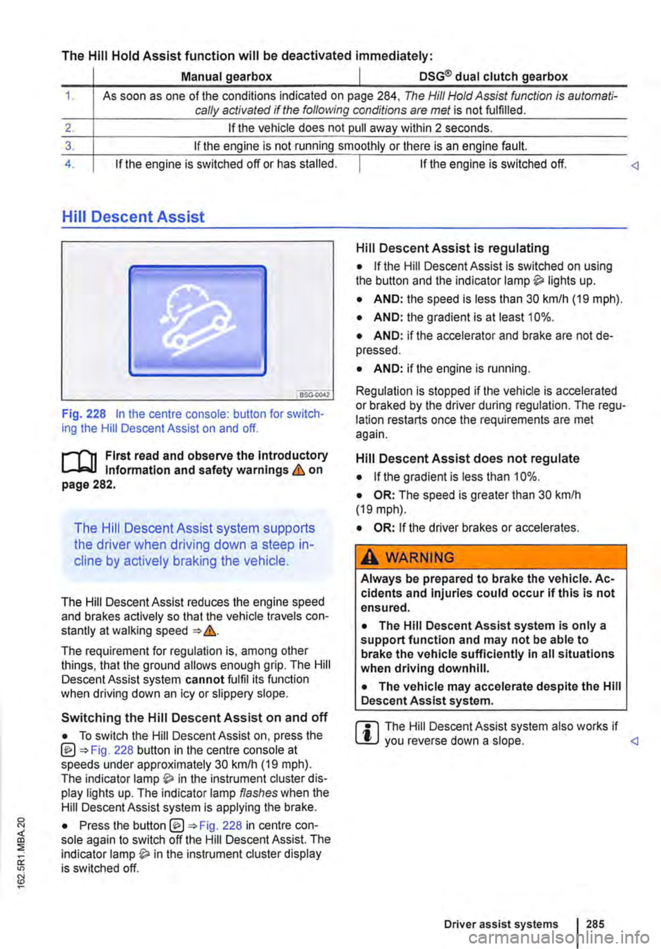
Fig. 228 In the centre console: button for switch-ing the Hill Descent Assist on and off.
l"'""'('n First read and observe the Introductory L-W.I Information and safety warnings & on page 282.
The Hill Descent Assist system supports
the driver when driving down a steep in-
cline by actively braking the vehicle.
The Hill Descent Assist reduces the engine speed and brakes actively so that the vehicle travels con-stantly at walking speed =>&.
The requirement for regulation is, among other things, that the ground allows enough grip. The Hill Descent Assist system cannot fulfil its function when driving down an icy or slippery slope.
Hill Descent Assist is regulating
• If the Hill Descent Assist is switched on using the button and the indicator lamp lights up.
• AND: the speed is less than 30 km/h (19 mph).
• AND: the gradient is at least 10%.
• AND: if the accelerator and brake are not de-pressed.
• AND: if the engine is running.
Regulation is stopped if the vehicle is accelerated or braked by the driver during regulation. The regu-lation restarts once the requirements are met again.
Hill Descent Assist does not regulate
• If the gradient is less than 10%.
• OR: The speed is greater than 30 km/h (19 mph).
• OR: If the driver brakes or accelerates.
A WARNING
Always be prepared to brake the vehicle. Ac-cidents and Injuries could occur if this is not ensured.
• The Hill Descent Assist system is only a support function and may not be able to brake the vehicle sufficiently In all situations when driving downhill.
• The vehicle may accelerate despite the Hill Descent Assist system.
• To switch the Hill Descent Assist on, press the @=>Fig. 228 button in the centre console at speeds under approximately 30 km/h (19 mph). The indicator in the instrument cluster dis-play lights up. The indicator lamp flashes when the Hill Descent Assist system is applying the brake.
r::l The Hill Descent Assist system also works if W you reverse down a slope.
Driver assist systems 285
Page 304 of 486
When the highest level is reached, the distance re-turns to the lowest level when the button is press-ed again.
The distance level can also be set using the Q or Q buttons on the multifunction steering wheel im-mediately after the(!) button on the multifunction steering Fig. 241 has been pressed.
Select the Settings menu, Assist systems submenu, ACC to set the distance to be used when the ACC is switched on 24.
Setting the gearbox programme
The acceleration response can be influenced by the gearbox programme selected. The programme can be set Using the ACC option in the Assistant submenu in the Settings menu. The following gearbox programmes can be selected:
• Normal
• Sport
• Eco
The following conditions can prevent the adaptive cruise control (ACC) from reacting:
• If the accelerator is depressed.
• If no gear is selected.
• If the ESC is taking corrective action.
• If there is a fault in several brake lights on the vehicle or on a trailer with an electrical connection to the vehicle.
• If the vehicle is reversing.
• System version 1: if the vehicle is travelling faster than approximately 160 km/h (1 00 m ph).
• System version 2: if the vehicle is travelling faster than approximately 210 km/h (130 mph).
A WARNING
If you do not maintain the minimum distance to a vehicle In front and the difference In speed between the two vehicles is so great that the braking action of the adaptive cruise control (ACC) is insufficient, you are In dan-ger of colliding with the vehicle in front. You should reduce the vehicle speed immediately with the foot brake.
• The adaptive cruise control (ACC) may not be able to detect all driving situations cor-rectly.
• Leaving your foot on the accelerator means that the adaptive cruise control (ACC) will not brake automatically. This is because manual acceleration overrides the system.
• You should always be prepared to brake the vehicle yourself.
• Observe country-specific regulations re-garding the minimum distance.
m The set speed will be deleted if the ignition or L!.J the adaptive cruise control (ACC) is switched off.
m The adaptive cruise control (ACC) is auto-L!.J matically deactivated when the traction con-trol system (TCS) is deactivated.
m In vehicles with a start/stop system, the en-L!.J gine is switched off automatically during the stationary phase of adaptive cruise control (ACC) and is then restarted for moving off.
situations
1""111 First read and observe the introductory L-J,:.IJ Information and safety warnings & on page 298.
The adaptive cruise control (ACC) should be switched off in the following situations due to sys-tem limitations &:
304 I While driving
• When turning off roads, driving around round-abouts, narrow curves, joining motorways, exiting from motorways or driving through road works, to prevent the vehicle from unnecessarily accelerat-ing to the set speed in these situations
• When driving through a tunnel as this situation could impair the system function.
• On roads with more than one lane, if other vehi-cles are driving more slowly in the fast lane. The slower vehicles In the other lane would be overtak-en from the right side in this case.
• In heavy rain, snow or spray as vehicles travel-ling ahead cannot be monitored sufficiently or maybe cannot be monitored at all. .,.
Page 338 of 486
Programming the supplementary heating system
r('n First read and observe the introductory L-Wl Information and safety warnings & on page 332.
In vehicles with camping equipment (California), the supplementary heater is programmed via the central control panel =>page 192.
Setting the date
Before being used for the first time and if the vehi-cle battery has been disconnected and reconnec-ted, the date needs to be set.
• Press any button on the roof display to activate the roof display.
• Press button @!) until the date is displayed.
• Press button @!) again. The day flashes.
• Press the function button .... or T until the re-quired day is displayed.
• Press button @!) again to confirm the day. The month flashes.
• Proceed in the same way for the month and the year.
Time
The time is automatically taken from the instrument cluster.
Setting the start time
You can programme up to three different start times. Only one of these can be activated at a time.
The following steps must be carried out in less than 10 seconds as the procedure will otherwise be stopped.
• Press any button on the roof display to activate the roof display.
• Press until OFF is displayed.
• Press the @) button, press function button .... or T as often as necessary until ON is displayed.
• Press the@) button to confirm.
• Press the function button .... or T until the re-quired temperature or mode is displayed.
• Press the @!) button to confirm.
• Press the function button .... or T as often as necessary until the start time to be switched on or off is displayed.
338 I While dnvmg
• Press the function button .... or T until the re-quired day of week is displayed. If a day is not dis-played, no day has been programmed, only a time. The supplementary heater will then be switched on at this programmed time.
• Press the @) button to confirm the selected day of the week. The hour menu is displayed.
• Proceed in the same way for the hour, for mi-nutes as well as the operating duration.
• Press the @) button to confirm the settings. A summary of the settings is displayed.
The start time for which the changes have been made has been activated. To activate additional start times, press and hold down for several seconds, select the start time with the func-tion buttons .... or T and then proceed as descri-bed above.
Deactivating the start time
If changes have been made for a start time, this start time still remains activated. To deactivate the start time, proceed as follows:
• Press any button on the roof display to activate the roof display.
• Push and hold down button for several seconds, then press the@) button until an active start time that is to be deactivated is displayed.
• Press the function button .... or T as often as necessary until OFF is displayed.
• Press the @) button to confirm.
The start time has now been deactivated and is no longer shown on the roof display.
A WARNING
Never program the supplementary heating system so that Is switched on and run In un-ventllated or enclosed areas. The fumes from the supplementary heating system contain carbon monoxide, which Is an odourless and colourless poisonous gas. Carbon monoxide can cause people to lose consciousness. lt can also cause death.
Page 410 of 486
If and when
Practical tips
Frequently asked questions
If you suspect that a vehicle fault has arisen or your vehicle has been damaged, read and observe the following information before contacting a Volkswagen Commercial Vehicles dealership or
qualified workshop. You may also find useful infor-mation in the index under the headings "Things to note" or "Checklist".
To note Some possible causes Possible solution
Vehicle battery is discharged. -How to jump start =>page 443. -Recharge vehicle battery 362.
Engine does not start. The incorrect vehicle key is be-Use a valid vehicle key 36. ing used.
Fuel level is too low. Fill the tank 340.
Supplementary heating system Switch off the supplementary heating
Smoke is coming from the is running. system 332. wing. Supplementary heater is run-No solution 345. ning.
-Battery in the remote control -Replace the battery 36. Vehicle cannot be locked or key is flat. -Move closer to the vehicle. unlocked with the remote -Located too far away from the -Synchronise the vehicle key =>page 36. vehicle. control key. -Buttons were pressed outside -Lock or unlock the vehicle manually
the range. 413.
Cold engine. brake assist sys-Refer to the index under entries for Unusual noises. tems, supplementary heating "Noises". system.
Assist systems are active. Refer to the index under entries for "As-sist systems". Unusual handling. DSG® dual clutch gearbox is too Stop the vehicle immediately hot. 266.
Front seats cannot be ad-Vehicle battery is discharged. Recharge vehicle battery 362.
justed electrically. Fuse blown. Check fuse and replace as necessary 429.
The vehicle has no vehicle No direct solutions possible as it depends
jack, spare wheel or break-Equipment depends on type of on the equipment level. Contact a Volks-vehicle. wagen Commercial Vehicles dealership if down set. necessary 416.
-Windows or sliding roof are open. The interior monitoring sys--Item attached to the interior Remove any objects that could trigger a tem triggers a false alarm. mirror is moving. false alarm 44. -A mobile telephone is vibrating inside the vehicle.
Functions are not working Settings have been made in the Check and if necessary reset back to fac-as described in the owner's manual. Volkswagen information system. tory settings 24.
410 I If and when
Page 412 of 486
Making you and your vehicle safe
8S0.00)7
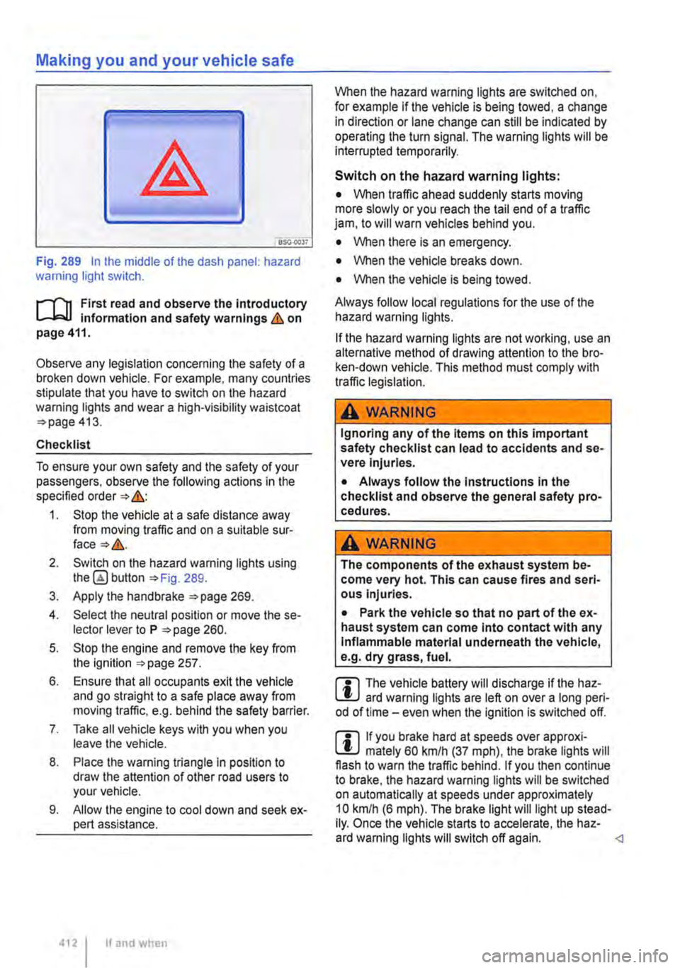
Fig. 289 In the middle of the dash panel: hazard warning light switch.
f"'""'('n First read and observe the Introductory L-lo:.U Information and safety warnings Lb. on page 411.
Observe any legislation concerning the safety of a broken down vehicle. For example, many countries stipulate that you have to switch on the hazard warning lights and wear a high-visibility waistcoat =>page 413.
Checklist
To ensure your own safety and the safety of your passengers, observe the following actions in the specified order => &:
1. Stop the vehicle at a safe distance away from moving traffic and on a suitable sur-face=>&.
2. Switch on the hazard warning lights using button =>Fig. 289.
3. Apply the handbrake =>page 269.
4. Select the neutral position or move the se-lector lever to P =>page 260.
5. Stop the engine and remove the key from the ignition =>page 257.
6. Ensure that all occupants exit the vehicle and go straight to a safe place away from moving traffic, e.g. behind the safety barrier.
7. Take all vehicle keys with you when you leave the vehicle.
8. Place the warning triangle in position to draw the attention of other road users to your vehicle.
9. Allow the engine to cool down and seek ex-pert assistance.
4121 If and when
When the hazard warning lights are switched on, for example if the vehicle is being towed, a change in direction or lane change can still be indicated by operating the turn signal. The warning lights will be interrupted temporarily.
Switch on the hazard warning lights:
• When traffic ahead suddenly starts moving more slowly or you reach the tail end of a traffic jam, to will warn vehicles behind you.
• When there is an emergency.
• When the vehicle breaks down.
• When the vehicle is being towed.
Always follow local regulations for the use of the hazard warning lights.
If the hazard warning lights are not working, use an alternative method of drawing attention to the bro-ken-down vehicle. This method must comply with traffic legislation.
A WARNING
Ignoring any of the items on this important safety checklist can lead to accidents and se-vere Injuries.
• Always follow the Instructions In the checklist and observe the general safety pro-cedures.
A wARNING
The components of the exhaust system be-come very hot. This can cause fires and seri-ous Injuries.
• Park the vehicle so that no part of the ex-haust system can come Into contact with any Inflammable material underneath the vehicle, e.g. dry grass, fuel.
m The vehicle battery will discharge if the haz-L.:!J ard warning lights are left on over a long peri-od of time -even when the Ignition is switched off.
m If you brake hard at speeds over approxi-L.:!J mately 60 km/h (37 mph), the brake lights will flash to warn the traffic behind. If you then continue to brake, the hazard warning lights will be switched on automatically at speeds under approximately 10 km/h (6 mph). The brake light will light up stead-Ily. Once the vehicle starts to accelerate, the haz-ard warning lights will switch off again.
Page 471 of 486
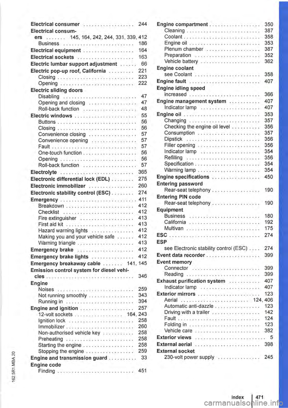
Electrical consumer . . . . . . . . . . . . . . . . . . 244
Electrical consum-ers ....... 145,164,242,244,331,339,412 Business . . . . . . . . . . . . . . . . . . . . 186
Electrical equipment . . . . . . . . . . . . . . . . . . 164
Electrical sockets . . . . . . . . . . . . . . . . . . . . 163
Electric lumbar support adjustment . . . . . . 66
Electric pop-up roof, California . . . . . . . . . 221 Closing . . . . . . . . . . . . . . . . . . . . . . . . . . . 223 Opening . . . . . . . . . . . . . . . . . . . . . . . . . . 222
Electric sliding doors Disabling . . . . . . . . . . . . . . . . . . . . . . . . . . 47 Opening and closing . . . . . . . . . . . . . . . . . 47 Roll-back function . . . . . . . . . . . . . . . . . . . 48 Electric windows . . . . . . . . . . . . . . . . . . . . . . 55 Buttons . . . . . . . . . . . . . . . . . . . . . . . . . . . . 56 Closing . . . . . . . . . . . . . . . . . . . . . . . . . . . . 56 Convenience closing . . . . . . . . . . . . . . . . . 57 Convenience opening . . . . . . . . . . . . . . . . 57 Fault .........................•.... 57 One-touch function . . . . . . . . . . . . . . . . . . . 56 Opening ........................... 56 Roll-back function . . . . . . . . . . . . . . • . . . . 57
Electrolyte . . . . . . . . . . . . . . . . . . . . . . . . . . 365
Electronic differential lock (EDL) . . . . . . . . 275
Electronic Immobilizer . . . . . . . . . . . . . . . . 260
Electronic stability control (ESC) . . . . . . . . 274
Emergency ........................... 411 Breakdown . . . . . . . . . . . . . . . . . . . . • . . . 412 Checklist . . . . . . . . . . . . . . . . . . . . . . . . . 412 Fire extinguisher . . . . . . . . . . . . . . . . . . . 413 First aid kit . . . . . . . . . . . . . . . . . . . . . . . . 413 Hazard warning lights . . . . . . . . . . . . . . . 412 Making you and your vehicle safe 412 Warning triangle . . . . . . . . . . . . . . 413
Emergency brake . . . . . . . . . . . . . . . . . . . . 412
Emergency brake lights . . . . . . . . . . . 412 Emergency breakaway cable . . . . . . . 141, 145
Emission control system for diesel vehi-cles . . . . . . . . . . . . . . . . . . . . . . . . . . . . . . . 346
Engine Noises . . . . . . . . . . . . . . . . . . . . . . . • . . . 259 Not running smoothly . . . . . . . . . . . . • . . . 343 Running in . . . . . . . . . . . . . . . . . . . . 394
Engine and ignition . . . . . . . . . . . . . . . . . . . 257 12-volt sockets . . . . . . • . . . . . . . . . . 164, 243 Ignition lock . . . . . . . . . . . . . . . . . . . . . . . 258 Immobilizer . . . . . . . . . . . . . . . . . . . . . . . . 260 Non-authorised vehicle key . . . . . . . . . . . 258 Preheating . . . . . . . . . . . . . . . . . . . 258 Starting the engine . . . . . . . . . . . . . . . . . . 258 Stopping the engine . . . . . . . . . . . . . . . . 259 Engine and transmission guard . . . . . . . . . . 33
Engine code Finding . . . . . . . . . . . . . . . . . . . . . . . . . . . 451
Engine compartment ................. . Cleaning ........................ . Coolant .......................... . Engine oil ........................ . Plenum chamber .................. . Preparation ...................... . Vehicle battery .................... . Engine coolant see Coolant ................. .
Engine fault ................... .
Engine idling speed increased ........................ . Engine management system .....•..... Indicator lamp .................... .
Engine oil .....................•..... Changing ........................ . Checking the engine oil level ......... . Consumption ................•..... Dipstick ......................... . Filler opening ..................... . Indicator lamp .................... . Refilling ......................... . Specification ...................... . Warning lamp ..................... .
Engine specifications ................ . Entering password Rear-seat telephony ......... .
Entering PIN code Rear-seat telephony ................ . Equipment Business ........................ . California ........................ . Multivan ... .
ESC ....... . ESP
350 387 358 353 387 352 362
358
407
366 407 407
353 357 356 357 356 356 354 356 354 354
450
190
190
180 192 175
274
see Electronic stability control (ESC) . . . . 274 Event data recorder . . . . . . . . . . . . . . . . . . . 399
Event memory Connector . . . . . . . . . . . . . . . . . . . . . . . 399 Reading . . . . . . . . . . . . . . . . . . . . . . . . . . 399 Exhaust purification system . . . . . . . . . . . 407 Indicator lamp . . . . . . . . . . . . . . . . . . . . . 407 Exterior mirrors . . . . . . . . . . . . . . . . . . . . 123 Aerial . . . . . . . . . . . . . . . . . . . . . . . . 124,406 Automatic anti-dazzle . . . . . . . . . . . . . . 123 Driving with a trailer . . . . . . . . . . . . . . . . 142 .............. ·····•········ Folding in . . . . . . . . . . . . . . . . . . . . . . . . . 123 Vehicle care . . . . . . . . . . . . . . . . . . . . . . . 382
Exterior views . . . . . . . . . . . . . . . . . • . . . . . . . 5
External aerial . . . . . . . . . . . . . . . . . . . . . . . 398 External socket 230-volt power supply 245
Index 471