air condition VOLKSWAGEN TRANSPORTER 2013 Service Manual
[x] Cancel search | Manufacturer: VOLKSWAGEN, Model Year: 2013, Model line: TRANSPORTER, Model: VOLKSWAGEN TRANSPORTER 2013Pages: 486, PDF Size: 69.28 MB
Page 332 of 486
![VOLKSWAGEN TRANSPORTER 2013 Service Manual Supplementary heaters (auxiliary air heater or auxiliary
coolant heater)
[Q] Introduction
This chapter contains information on the following subjects:
Controls . . . . . . . . . . . . . . . . . . VOLKSWAGEN TRANSPORTER 2013 Service Manual Supplementary heaters (auxiliary air heater or auxiliary
coolant heater)
[Q] Introduction
This chapter contains information on the following subjects:
Controls . . . . . . . . . . . . . . . . . .](/img/18/55784/w960_55784-331.png)
Supplementary heaters (auxiliary air heater or auxiliary
coolant heater)
[Q] Introduction
This chapter contains information on the following subjects:
Controls . . . . . . . . . . . . . . . . . . . . . . . . . . . . . . . 333
Switching the supplementary heating system on and off . . . . . . . . . . . . . . . . . . . . . . . . 334
Remote control . . . . . . . . . . . . . . . . . 335
Programming the supplementary heating system . . . . . . . . . . . . . . . . . . . . . . 338 Switching the child proof lock on and off . . . . . 339
Operation . . . . . . . . . . . . . . . . . . . . . . . . 339
The supplementary heating system is supplied with fuel from the vehicle fuel tank and can be used when the vehicle is in motion or stationary. Electri-cal power is supplied by the vehicle battery.
The auxiliary air heater runs in air recirculation mode and heats the vehicle interior. it has sepa-rate vents in the passenger compartment =>Fig. 265.
The auxiliary coolant heater heats the heating circuit. Heat is guided into the vehicle interior via the vents for the heating or air conditioning system. With the auxiliary coolant heater, it is possible to switch between heating and ventilating.
Additional information and warnings:
• Supplementary heater in the California =>page 192
• Filling the tank =>page 340
• Battery =>page 362
Swallowing batteries with a diameter of 20 mm or other lithium batteries can result in severe or even fatal injuries within a very short period of time.
• Always keep the vehicle key, key ring with batteries, spare batteries, round cells and other batteries that are larger than 20 mm out of the reach of children.
332 I While driving
• Call for medical help immediately you pect that someone has swallowed a batte
A WARNING
The fumes from the supplementary heating system contain carbon monoxide, which is an odourless and colourless poisonous gas. Carbon monoxide can cause people to lose consciousness. lt can also cause death.
• Never start or run the supplementary heat-ing system In unventllated or closed rooms.
• Never program the supplementary heating system so that Is switched on and run In un-ventilated or enclosed areas.
A WARNING
Parts of the exhaust system of the supple-mentary heating system become very hot. This can cause fires.
• Park the vehicle so that no part of the ex-haust system can come Into contact with any Inflammable material underneath the vehicle, e.g. dry grass.
Q)
Do not place any food, medicine or any other temperature-sensitive items in front of the vents. Heat-sensitive food, medicine and other items could be either damaged or rendered useless.
m After starting the engine with a discharged W vehicle battery, or after the battery has been changed, system settings (time, date, personal convenience settings and programming) may have been changed or deleted. Check and correct the settings as necessary once the vehicle battery has been sufficiently charged.
Page 333 of 486
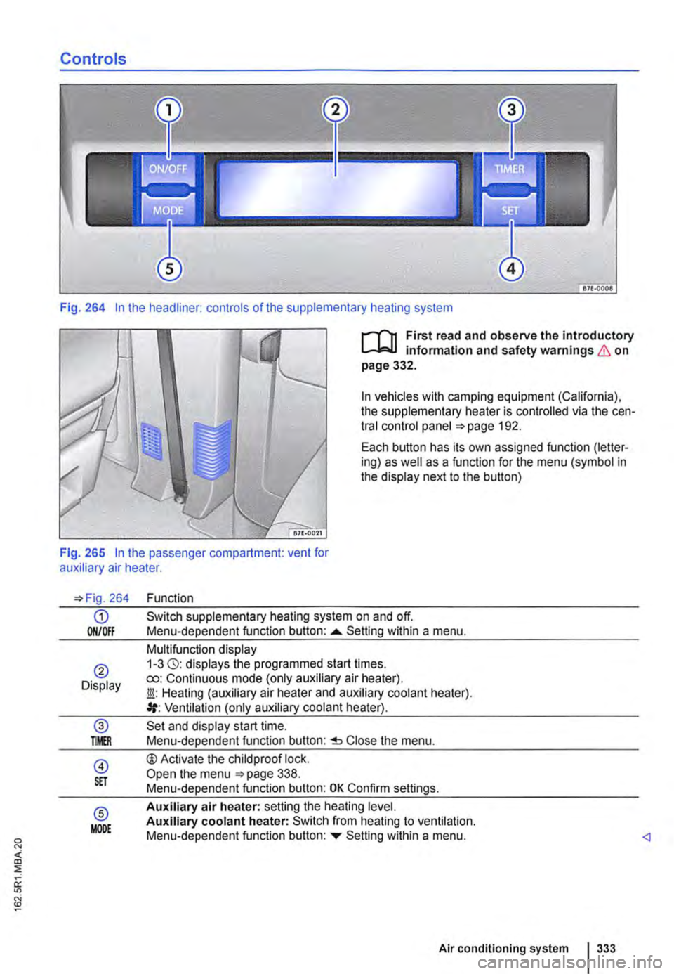
Controls
Fig. 264 In the headliner: controls of the supplementary heating system
I""""T'n First read and observe the introductory l.-..1=.1.1 infonmatlon and safety warnings & on page 332.
In vehicles with camping equipment (California), the supplementary heater is controlled via the cen-tral control panel 192.
Each button has its own assigned function (letter-ing) as well as a function for the menu (symbol in the display next to the button)
Fig. 265 In the passenger compartment: vent for auxiliary air heater.
264
G) ON/Off
® Display
@ TMR
@ S£T
® MODE
Function
Switch supplementary heating system on and off. Menu-dependent function button: ......_ Setting within a menu.
Multifunction display 1-3 (3): displays the programmed start times. ro: Continuous mode (only auxiliary air heater). Jli: Heating (auxiliary air heater and auxiliary coolant heater). Ventilation (only auxiliary coolant heater).
Set and display start time. Menu-dependent function button: Close the menu.
®Activate the child proof lock. Open the menu 338. Menu-dependent function button: OK Confirm settings.
Auxiliary air heater: setting the heating level. Auxiliary coolant heater: Switch from heating to ventilation. Menu-dependent function button: ...,. Setting within a menu.
Air conditioning system I 333
Page 335 of 486
Remote control
B
BSG·OOS3
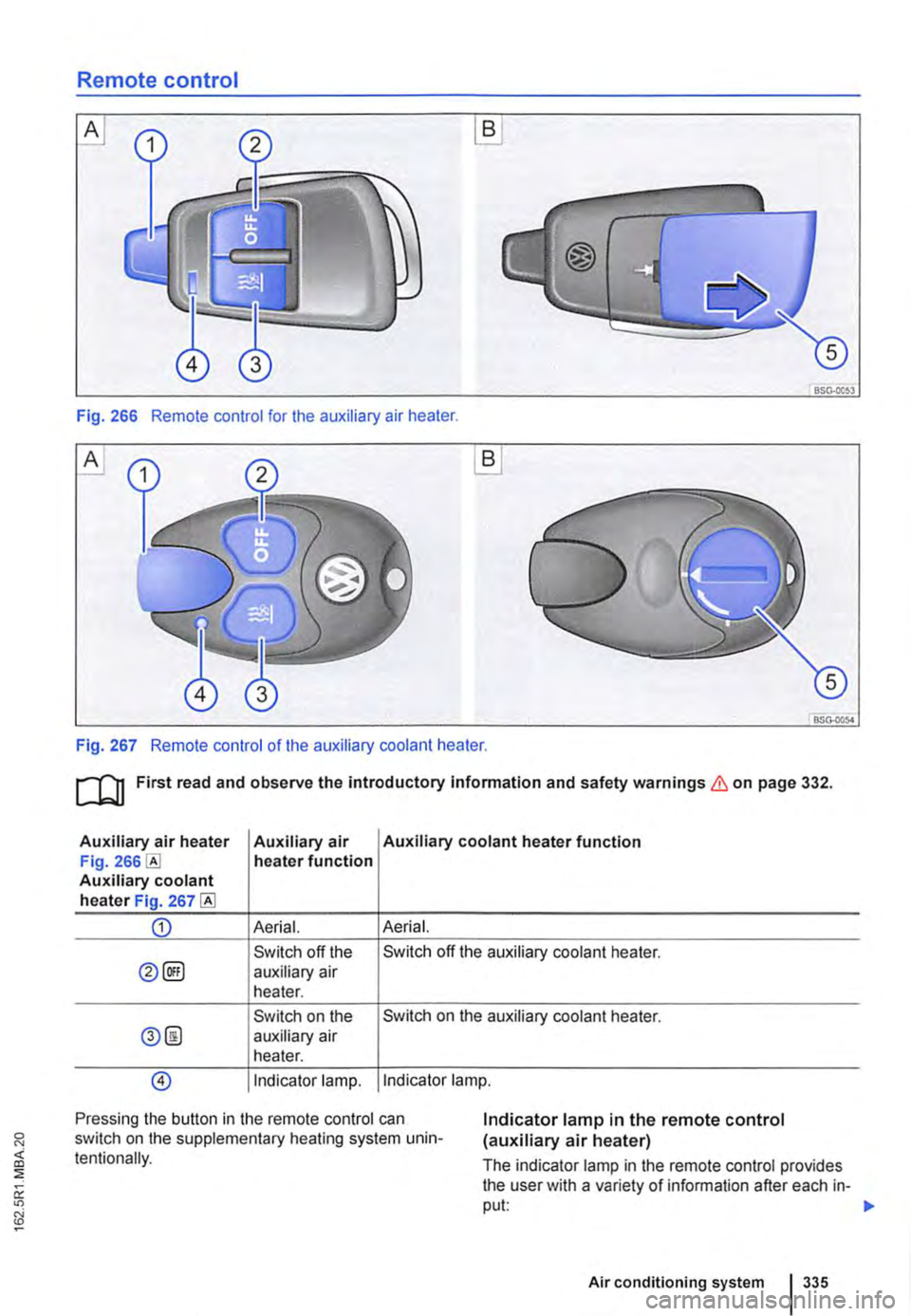
Fig. 266 Remote control for the auxiliary air heater.
A
BSG-0054
Fig. 267 Remote control of the auxiliary coolant heater.
ru First read and observe the introductory Information and safety warnings & on page 332.
Auxiliary air heater Auxiliary air Auxiliary coolant heater function Fig. heater function Auxiliary coolant heater Fig. 267
CD Aerial. Aerial.
Switch off the Switch off the auxiliary coolant heater.
0@) auxiliary air heater.
Switch on the Switch on the auxiliary coolant heater.
0@ auxiliary air heater.
@) Indicator lamp. Indicator lamp.
Pressing the button in the remote control can switch on the supplementary heating system unin-tentionally.
Indicator lamp in the remote control (auxiliary air heater)
The indicator lamp in the remote control provides the user with a variety of information after each in-put: 1>-
Air conditioning system 335
Page 337 of 486
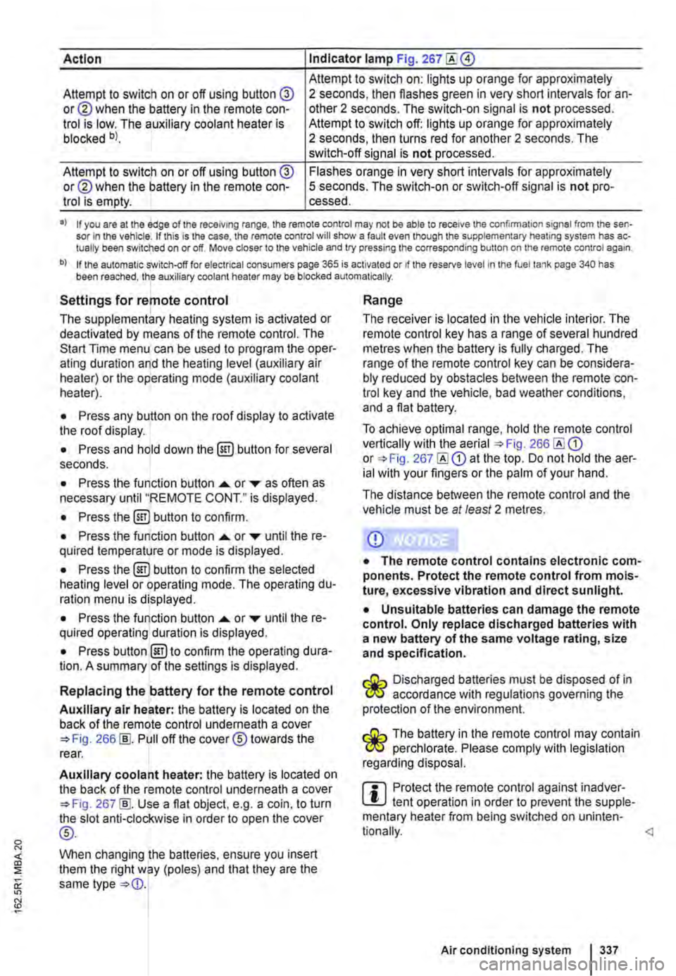
Action Indicator lamp Fig. 267
Attempt to switch on: lights up orange for approximately Attempt to switch on or off using button @ or@ when the battery in the remote con-trol is low. The auxiliary coolant heater is blocked bl.
2 seconds, then flashes green in very short intervals for an-other 2 seconds. The switch-on signal is not processed. Attempt to switch off: lights up orange for approximately 2 seconds, then turns red for another 2 seconds. The switch-off signal is not processed.
Attempt to switch on or off using button @ or@ when the battery in the remote con-trol is empty.
Flashes orange in very short intervals for approximately 5 seconds. The switch-on or switch-off signal is not pro-cessed.
•> If you are at the edge of the receiving range, the remote control may not be able to receive the confirmation signal from the sen-sor in the vehicle. If this is the case, the remote control will show a fault even though the supplementary heating system has ac-tually been switched on or off. Move closer to the vehicle and try pressing the corresponding button on the remote control again.
b) If the automatic switch-off for electrical consumers page 365 is activated or if the reserve level in lhe fuel tank page 340 has been reached, the auxiliary coolant heater may be blocked automatically.
Settings for remote control
The supplementary heating system is activated or deactivated by means of the remote control. The Start Time menu can be used to program the oper-ating duration and the heating level (auxiliary air heater) or the operating mode (auxiliary coolant heater).
• Press any button on the roof display to activate the roof display.
• Press and hold down the (ill) button for several seconds.
• Press the function button ...... or ,... as often as necessary until "REMOTE CONT." is displayed.
• Press the (ill) button to confirm.
• Press the function button ...... or ,... until the re-quired temperature or mode is displayed.
• Press the (ill) button to confirm the selected heating level or operating mode. The operating du-ration menu is displayed.
• Press the function button ...... or ,... until the re-quired operating duration is displayed.
• Press button @)to confirm the operating dura-tion. A summary of the settings is displayed.
Replacing the battery for the remote control
Auxiliary air heater: the battery is located on the back of the remote control underneath a cover 266 [ID. Pull off the cover® towards the rear.
Auxiliary coolant heater: the battery is located on the back of the remote control underneath a cover 267 [ID. Use a flat object, e.g. a coin, to turn the slot anti-clockwise in order to open the cover
®-
When changing the batteries, ensure you insert them the right way (poles) and that they are the same type
Range
The receiver is located in the vehicle interior. The remote control key has a range of several hundred metres when the battery is fully charged. The range of the remote control key can be considera-bly reduced by obstacles between the remote con-trol key and the vehicle, bad weather conditions, and a flat battery.
To achieve optimal range, hold the remote control vertically with the aerial 266 or 267 at the top. Do not hold the aer-ial with your fingers or the palm of your hand.
The distance between the remote control and the vehicle must be at least 2 metres.
CD
• The remote control contains electronic com-ponents. Protect the remote control from mois-ture, excessive vibration and direct sunlight.
• Unsuitable batteries can damage the remote control. Only replace discharged batteries with a new battery of the same voltage rating, size and specification.
Discharged batteries must be disposed of in W accordance with regulations governing the protection of the environment.
The battery in the remote control may contain W perchlorate. Please comply with legislation regarding disposal.
m Protect the remote control against inadver-L!.J tent operation in order to prevent the supple-mentary heater from being switched on uninten-
Air conditioning system I 337
Page 339 of 486
Switching the childproof lock on and off
B7f·0201
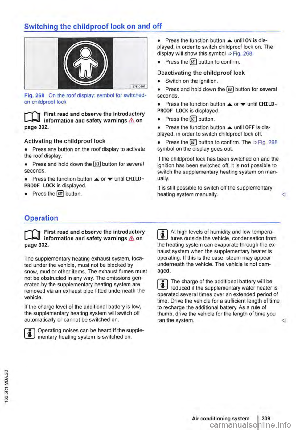
Fig. 268 On the roof display: symbol for switched-on child proof lock
r-T'n First read and observe the introductory L-.bU information and safety warnings & on page 332.
Activating the childproof lock
• Press any button on the roof display to activate the roof display.
• Press and hold down the @) button for several seconds.
• Press the function button .... or ..-until CHILD-PROOF LOCK is displayed.
• Press the@) button.
Operation
r-T'n First read and observe the introductory L-.bU information and safety warnings & on page 332.
The supplementary heating exhaust system, loca-ted under the vehicle, must not be blocked by snow, mud or other items. The exhaust fumes must not be obstructed in any way. The emissions gen-erated by the supplementary heating system are removed via an exhaust pipe fitted underneath the vehicle.
If the charge level of the additional battery is low, the supplementary heating system will switch off automatically or cannot be switched on.
m Operating noises can be heard if the supple-l!J mentary heating system is switched on.
• Press the function button .... until ON is dis-played, in order to switch child proof lock on. The display will show this symbol =>Fig. 268.
• Press the @] button to confirm.
Deactivating the childproof lock
• Switch on the ignition.
• Press and hold down the@] button for several seconds.
• Press the function button....._ or..-until CHILD-PROOF LOCK is displayed.
• Press the@) button.
• Press the function button .... until OFF is dis-played. in order to switch child proof lock off.
• Press the@) button to confirm. The =>Fig. 268 symbol on the display goes out.
If the child proof lock has been switched on and the ignition has been switched off, it is not possible to switch the supplementary heating system on man-ually.
lt is still possible to switch off the supplementary heating system manually.
r::l The charge of the additional battery will be W reduced if the supplementary water heater is operated several times over an extended period of time. Drive the vehicle for a sufficient length of time to recharge the additional battery. As a rule of thumb, drive the vehicle for the length of time you ran the system.
Page 345 of 486
CD
• Fuels that are identified at the fuel pump as containing metallic additives may not be used. LRP fuel (lead replacement petrol) also con-tains high concentrations of metallic additives. Risk of engine damage I
Diesel
r'""'('n First read and observe the Introductory L-J,:.U Information and safety warnings & on page 343.
Diesel
Diesel fuel must comply with the European stand-ard EN 590 (in Germany DIN EN 590).
The service intervals are shorter if you use diesel with a high sulphur content =>Booklet Service schedule =>CD. A Volkswagen Commercial Vehicles dealership will be able to tell you which countries have diesel with a high sulphur content.
Where diesel fuel complying with the EN 590 standard is not available, Volkswagen Commercial Vehicles dealerships and filling stations will have information on which fuels do comply with the EN 590 standard.
Do not mix fuel additives (thinners. or similar addi-tives) with diesel.
Winter diesel
When using summer-grade diesel. difficulties may be experienced at temperatures below o•c (+32.F)
because the fuel thickens due to paraffin separa-tion. For this reason winter-grade diesel which can be used at temperatures below -2o•c (·4°F) is available in countries such as Germany during the cold months.
In countries with different climatic conditions the diesel sold generally has different temperature characteristics. Check with a Volkswagen Com-mercial Vehicles dealer or filling stations in the country concerned regarding the type of diesel fuels available.
it is not unusual for a cold diesel engine to be loud-er in cold temperatures that in warm weather. In addition, exhaust emissions may be tinged with blue while the engine starts and reaches operating temperature. The amount of exhaust fumes de-pends on the outside temperature.
CD
• Just one tankful of leaded fuel, or fuel con-taining other metallic additives, can seriously Impair the efficiency of the catalytic converter and can also cause considerable damage to the catalytic converter and engine.
Diesel vehicles are equipped with a filter pre-heat-er system. This ensures that the fuel system re-mains operational even down to approximately -24•c (-11.F) provided that winter-grade diesel which is safe down to -15•c (+5.F) is used.
However, if the fuel has thickened to such an ex-tent that the engine will not start at temperatures below -24•c (-11.F) simply place the vehicle in a warm garage or workshop for a while.
Supplementary heater
Vehicles fitted with a diesel engine may also be equipped with a fuel-driven supplementary heater. This heater is powered with fuel from the vehicle tank. In this case, odour and water vapour may es-cape from the vehicle, and there may be a greater quantity of smoke. This is quite normal when the system is in use, and does not indicate damage or a fault in the system.
The supplementary heater will be switched off au-tomatically if the level in the fuel tank is low (re-serve level).
A WARNING
Never use a start booster. Start boosters may explode or cause the engine to suddenly run at high revs, which can cause serious Injuries and engine damage.
CD
• Before filling up with diesel, check whether the fuel corresponds to the vehicle's require-ments according to the fuel standard Informa-tion at the pump.
• Only use fuel that complies with the EN 590 standard and has the correct cetane number. Otherwise, the engine and the fuel system can suffer considerable damage. The engine can al-so lose power or fall. ..,.
At the filling station 1345
Page 376 of 486
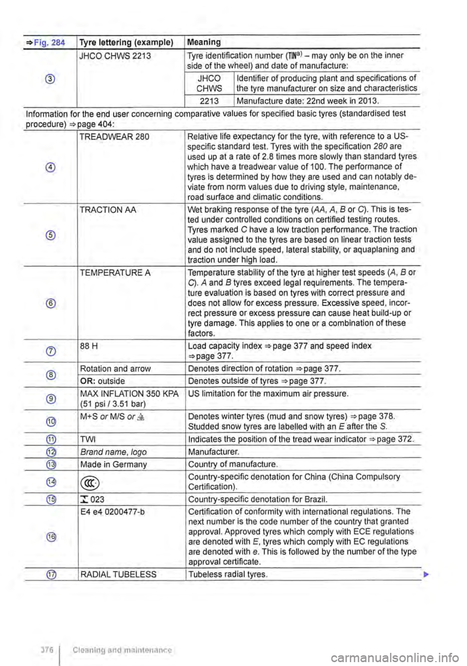
=>Fig. 284 Tyre lettering (example) I Meaning
JHCO CHWS 2213 Tyre identification number (TINa)-may only be on the inner side of the wheel) and date of manufacture:
® JHCO Identifier of producing plant and specifications of CHWS the tyre manufacturer on size and characteristics
2213 Manufacture date: 22nd week in 2013.
Information for the end user concernmg comparat1ve values for spec1fied bas1c tyres (standardised test procedure) =>page 404·
TREADWEAR 280 Relative life expectancy for the tyre, with reference to a US-specific standard test. Tyres with the specification 280 are used up at a rate of 2.8 times more slowly than standard tyres
@ which have a treadwear value of 100. The performance of tyres is determined by how they are used and can notably de-viate from norm values due to driving style, maintenance, road surface and climatic conditions.
TRACTION AA Wet braking response of the tyre (AA, A, B or C). This is tes-led under controlled conditions on certified testing routes.
® Tyres marked C have a low traction performance. The traction value assigned to the tyres are based on linear traction tests and do not include speed, lateral stability, or aquaplaning and traction under high load.
TEMPERATURE A Temperature stability of the tyre at higher test speeds (A, B or C). A and B tyres exceed legal requirements. The tempera-tu re evaluation is based on tyres with correct pressure and
® does not allow for excess pressure. Excessive speed, incor-reel pressure or excess pressure can cause heat build-up or tyre damage. This applies to one or a combination of these factors.
0 88 H Load capacity index ::.page 377 and speed index ::.page 377.
® Rotation and arrow Denotes direction of rotation ::.page 377.
OR: outside Denotes outside of tyres ::.page 377.
® MAX INFLATION 350 KPA US limitation for the maximum air pressure. (51 psi /3.51 bar)
® M+S or M/S or & Denotes winter tyres (mud and snow tyres) ::.page 378. Studded snow tyres are labelled with an E after the S.
® TWI Indicates the position of the tread wear indicator ::.page 372.
@ Brand name. logo Manufacturer.
@ Made in Germany Country of manufacture.
@> @ Country-specific denotation for China (China Compulsory Certification).
® :r 023 Country-specific denotation for Brazil.
E4 e4 0200477-b Certification of conformity with international regulations. The next number is the code number of the country that granted
® approval. Approved tyres which comply with ECE regulations are denoted with E. tyres which comply with EC regulations are denoted with e. This is followed by the number of the type approval certificate.
@ RADIAL TUBELESS Tubeless radial tyres.
376 I Cleaning and maintenance
Page 379 of 486
Snow chains
r-"f"'n First read and observe the introductory L-J=.IJ information and safety warnings & on page 367.
Please heed legislation and also the permitted speed when driving your vehicle with snow chains.
In winter conditions, snow chains will not only im-prove acceleration, but also braking response.
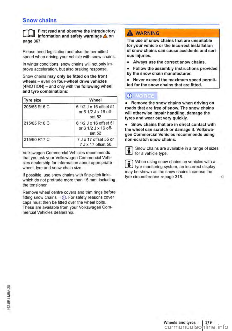
Snow chains may only be fitted on the front wheels-even on four-wheel drive vehicles (4MOTION)-and only with the following wheel and tyre combinations:
Tyre size Wheel
205/65 R16 C 6 1/2 J x 16 offset 51 or61/2Jx16off-set 52
215/65 R16 C 6 112 J x 16 offset 51 or61/2 J x 16 off-set 52
215/60 R17 C 7 J x 17 offset 55 or 7 J x 17 offset 56
Volkswagen Commercial Vehicles recommends that you ask your Volkswagen Commercial Vehi-cles dealership for information about appropriate wheel, tyre and snow chain size.
If possible, use snow chains with fine-pitch links which do not protrude more than 15 mm, including the tensioner.
Remove wheel centre covers and trim rings before fitting snow chains For safety reasons cover caps must then be fitted over the wheel bolts. These are available from your Volkswagen Com-mercial Vehicles dealership.
A WARNING
The use of snow chains that are unsuitable for your vehicle or the incorrect installation of snow chains can cause accidents and seri-ous Injuries.
• Always use the correct snow chains.
• Follow the assembly instructions provided by the snow chain manufacturer.
• Never exceed the maximum speed permit-ted for the snow chains that are fitted.
Q)
• Remove the snow chains when driving on roads that are free of snow. The snow chains will otherwise impair handling, damage the tyres and wear out very quickly.
• Snow chains that are in direct contact with the wheel can scratch or damage it. Volkswa-gen Commercial Vehicles recommends using non-scratch snow chains.
m Snow chains are available in a range of sizes l!:.J for a vehicle type.
m When using snow chains on vehicles with a l!:.J tyre monitoring system, an incorrect display may be shown as the snow chains increase the tyre circumference 318.
Page 386 of 486
Remove stubborn impurities carefully using white spirits. and then rinse using warm water. Do not use any aggressive substances such as petrol, thinner or solvents.
Care of the decorative film
Basically, the same care instructions for vehicle paint apply =>page 384.
Treat the decorative film regularly, every 3 months (no longer) with liquid hot wax. Hot wax smooths the surface and has a dirt-repellent effect.
Only use soft microfibre clothes to apply it.
Volkswagen Commercial Vehicles recommends that you seek advice from a Volkswagen Commer-cial Vehicles partner or workshop as to a suitable care product.
Cleaning wheels
rill First read and observe the introductory information and safety warnings & on page 380.
Cleaning steel wheels
An industrial cleaner is needed to remove accumu-lated brake dust. Steel wheels should therefore be cleaned regularly with a separate sponge.
Any damage to the paint on steel wheels should be touched up before the metal starts to rust.
Caring for and cleaning alloy wheels
Wash grit and brake dust from alloy wheels ap-proximately every 2 weeks. Then use an acid-free detergent to clean the wheels. Volkswagen Corn-
Care of rubber seals
rill First read and observe the Introductory Information and safety warnings & on page 380.
The rubber seals on the doors, windows etc. will seal better, remain flexible and last longer if they are treated at regular intervals with a suitable care product.
386 Cleanmg and maintenance
• Depending on the condition of the brushes and car wash, fine scratches may appear In the decorative film.
• Remove impurities on the decorative film as soon as possible using suitable cleaning agents in order to avoid long-term damage to the film.
r::l If the surface of the decorative film is dam-L!.J aged, e.g. by the impact of gravel, the dam-age can only be rectified by replacing the whole decorative film element. Volkswagen Commercial Vehicles recommends having the work carried out by a qualified workshop.
it is important to remove road salt and brake dust by washing the wheels at regular intervals, to deter corrosion to the alloy.
Always use an acid-free detergent for alloy wheels. Car polish or other abrasive agents should not be used on the wheels.
If the protective coating is damaged, e.g. by stone impact, the damaged area should be repaired im-mediately.
Page 393 of 486
A wARNING
Check the condition of all seat belts regularly. If the belt webbing or any other part of the seat belt becomes damaged have it removed and replaced immediately by a qualified workshop. Damaged seat belts are very dan-gerous and can cause severe or fatal injuries.
• Never use chemical cleaning agents on the seat belts or their components. Further-more the seat belts may not come Into con-tact with corrosive fluids, solvents or sharp objects. These could considerably weaken the webbing.
• After cleaning, allow seat belts to dry completely before rolling them up. Otherwise the automatic belt retractors could become damaged and thus Impair their function.
Cleaning cool box
)""""'('n First read and observe the Introductory L.-J,:,JJ Information and safety warnings & on page 388.
Cleaning seat rails
)""""'('n First read and observe the introductory information and safety warnings & on page 388.
Clean the surface of the seat rails on a regular ba-sis
• Use a narrow nozzle on a vacuum cleaner to remove sand, dirt etc. from the seat rails.
Cleaning opaque shades
)""""'('n First read and observe the introductory information and safety warnings & on page 388.
For the best cleaning results have the opaque shades dry cleaned.
A WARNING (ConUnued)
• Avoid allowing foreign bodies or liquids to enter the slot for the seat belt buckle. This could prevent the belt buckle and seat belt from working properly.
• Never try to repair, modify or remove the seat belts yourself.
• Damaged seat belts must be replaced im-mediately with new seat belts approved by Volkswagen Commercial Vehicles for your ve-hicle type. Seat belts subjected to stress and stretched during an accident must be re-placed by a qualified workshop. Renewal may be necessary even if there is no apparent damage. The belt anchorage should also be checked.
• Clean the cool box with a household detergent before using it for the first time and whenever it needs cleaning.
• To prevent mould and mildew from forming in the cool box when it is not being used for long peri-ods, place a folded dry towel between the box and its lid.
CD
If seats are moved when the seat rails are soiled, the seat rails and the seat feet could be damaged.
Please refer to the information on the labels sewn into the opaque shades before cleaning in a wash-ing machine.
Vehicle care and maintenance 393