driving conditions VOLKSWAGEN TRANSPORTER 2014 Owner's Guide
[x] Cancel search | Manufacturer: VOLKSWAGEN, Model Year: 2014, Model line: TRANSPORTER, Model: VOLKSWAGEN TRANSPORTER 2014Pages: 486, PDF Size: 69.28 MB
Page 312 of 486
System limits
r-('n First read and observe the Introductory L-J,:.U Information and safety warnings & on page 307.
The area monitoring system (Front Assist) has physical and system-related limits. The driver may therefore feel that, in certain circumstances, some Front Assist reactions occur unexpectedly or with a delay. You should therefore always be prepared to take full control of the vehicle if necessary.
The following conditions can prevent Front Assist from reacting, or cause a delay in its reaction:
• In tight bends.
• If the accelerator is fully depressed.
• If Front Assist is switched off or there is a fault.
• If TCS or ESC is switched off manually.
• If the ESC is taking corrective action.
• If there is a fault in several brake lights on the vehicle or on a trailer with an electrical connection to the vehicle.
• If the radar sensor is dirty or covered.
• If the vehicle is reversing.
• Under hard acceleration.
• In snow or heavy rain.
• In case of narrow vehicles, e.g. motorbikes.
• If vehicles are travelling slightly to the left or right of your vehicle.
• If vehicles are crossing in front of your vehicle.
• If there is oncoming traffic.
• In uncertain traffic situations.
• 1/Vhen loads or attachment parts on other vehi-cles protrude to the side, rear or above the normal dimensions of the vehicle.
COJ Introduction
This chapter contains information on the following subjects:
Indicator lamp ... .
Operation ....... .
Driving situations ..........•.............
313
314
315
The lane change assist system (Side As-
sist) provides assistance when checking
for traffic behind the vehicle.
The lane change assist system cannot be switched on if the factory-fitted towing bracket is electrically connected to the trailer. The lane change assist system must be switched off manually for non-fac-tory-fitted towing brackets.
The lane change assist system has been designed for use on surfaced roads only.
Additional information and warnings:
• Exterior views =<>page 5
• Volkswagen information system =<>page 24
• Accessories, modifications, repairs and renewal of parts =<>page 394.
3121 While drivmg
A WARNING
The Intelligent technology of the lane change assist system (Side Assist) cannot change the laws of physics or the system-related ve-hicle limitations. Always take care when us-Ing the lane change assist system as you could otherwise cause accidents or Injuries. The system Is not a substitute for the full concentration of the driver.
• Adapt your speed and distance from the vehicles ahead to suit visibility, weather, road and traffic conditions.
• Your hands should always be on the steer-Ing wheel so that you can steer at any time.
• Pay attention to the visual displays in the exterior mirror housing and in the Instrument cluster display, and respond to the com-mands.
• The lane change assist system may react to special roadside structures, e.g. high or offset crash barriers. This can lead to error warnings. ,..
Page 315 of 486
![VOLKSWAGEN TRANSPORTER 2014 Owners Guide Driving situations
A
(I
Fig. 249 [A] Driving situation when overtaking with traffic behind the vehicle [81 Visual display in the left-hand exterior mirror.
A
Fig. 250 situation when overtaking an](/img/18/55783/w960_55783-314.png "VOLKSWAGEN TRANSPORTER 2014 Owners Guide Driving situations
A
(I
Fig. 249 [A] Driving situation when overtaking with traffic behind the vehicle [81 Visual display in the left-hand exterior mirror.
A
Fig. 250 situation when overtaking an")
Driving situations
A
(I
Fig. 249 [A] Driving situation when overtaking with traffic behind the vehicle [81 Visual display in the left-hand exterior mirror.
A
Fig. 250 situation when overtaking and pulling in. [B' Visual display in the right-hand exterior mirror.
rll1 First read and observe the introductory L-W.I Information and safety warnings & on page 312.
The following driving situations trigger a light in the exterior mirror 249 [ID (arrow) or 250 [ID (arrow):
• When another vehicle is overtaking your vehi-cle 249
• When overtaking another vehicle 250 with a speed difference of up to approximately 15 km/h (9 m ph). No display will be shown if the take-over manoeuvre is much faster.
The display in the exterior mirror will be shown ear-lier the faster you are nearing another vehicle as the lane change assist system calculates the
speed difference to other vehicles. For this reason, the display could be activated at different times de-spite your vehicle being at the same distance from other vehicles.
Physical and system-specific limits
The lane change assist system might, for example, interpret the traffic situation incorrectly in certain driving situations. In the following situations, for ex-ample:
• In tight bends.
• When road lanes are of varying width.
• At the brow of a hill.
• In poor weather conditions.
• Where there are special roadside structures, e.g. high or offset crash barriers. <1
Driver Alert System (recommendation for rest breaks)
o::n Introduction
This chapter contains information on the following subjects:
Function and operation by the user.. . . . 316
The Driver Alert System informs the driv-
er if their driving shows signs of tired-
ness.
Driver assist systems 315
Page 316 of 486
Additional information and warnings:
• Volkswagen information system =>page 24
• Accessories, modifications, repairs and renewal of parts (information stored in the control units) =>page 394
A WARNING
The Intelligent technology used In the Driver Alert System cannot overcome the laws of physics, and functions only within the limits of the system. Do not let the extra conven-ience afforded by the Driver Alert System tempt you Into taking any risks when driving -this can cause accidents. During a long trip, plan regular and sufficient breaks.
• The driver Is responsible at all times for their fitness to drive.
• Never drive a vehicle when you are tired.
Fig. 251 On the instrument cluster display: Driver Alert System.
r--('n First read and observe the Introductory Information and safety warnings&. on page 315.
The Driver Alert System determines the driving be-haviour at the beginning of a journey and uses it to evaluate the tiredness of the driver. This is com-pared to the behaviour of the driver while actually driving. If the system detects that the driver may be tired, an acoustic warning signal ("gong") will sound and an explanatory message or symbol (BREAK or =>Fig. 251) will appear in the instrument cluster display. The message on the instrument cluster display appears for about five seconds and may be repeated once. The last displayed mes-sage is saved by the system.
The message in the instrument cluster display can be switched off by pressing the (OK/RESIT I button on the wiper lever or the@ button on the multifunc-
316 I Whole driving
A WARNING (Continued)
• The system cannot always detect the driv-er's level of alertness. Observe the Informa-tion In the section "Function limitations" =>page 316.
• In certain situations, the system may wrongly Interpret Intentional driving manoeu-vres as a lack of alertness from the driver.
• No urgent warning will be given In the event of the phenomenon known as "micro-sleep".
• Follow the Information on the Instrument cluster display and respond according to the commands.
m The Driver Alert System has been developed l!..J for use only while driving on highways and good roads.
m If there is a system fault, proceed to a quali-L!..J fied workshop immediately to have the sys-tem checked.
Functional limitations
The driving behaviour can be only be evaluated at speeds over approximately 65 kmlh (40 mph) and up to approximately 200 km/h (125 m ph).
Switching on and off
The system can be activated or deactivated in the Assistants menu =>page 24. A tick indicates that a driver assist system is switched on.
Function limitations
The Driver Alert System has system-related limita-tions. The following conditions can limit the func-tion of the Driver Alert System, or prevent it from working altogether:
• When travelling at speeds of less than approxi-mately 65 km/h (40 mph).
• When travelling at speeds of more than approx-imately 200 km/h (125 mph).
• Roads with bends.
• Roads with uneven surfaces.
• Adverse weather conditions.
• Sporty driving style. .,..
Page 320 of 486
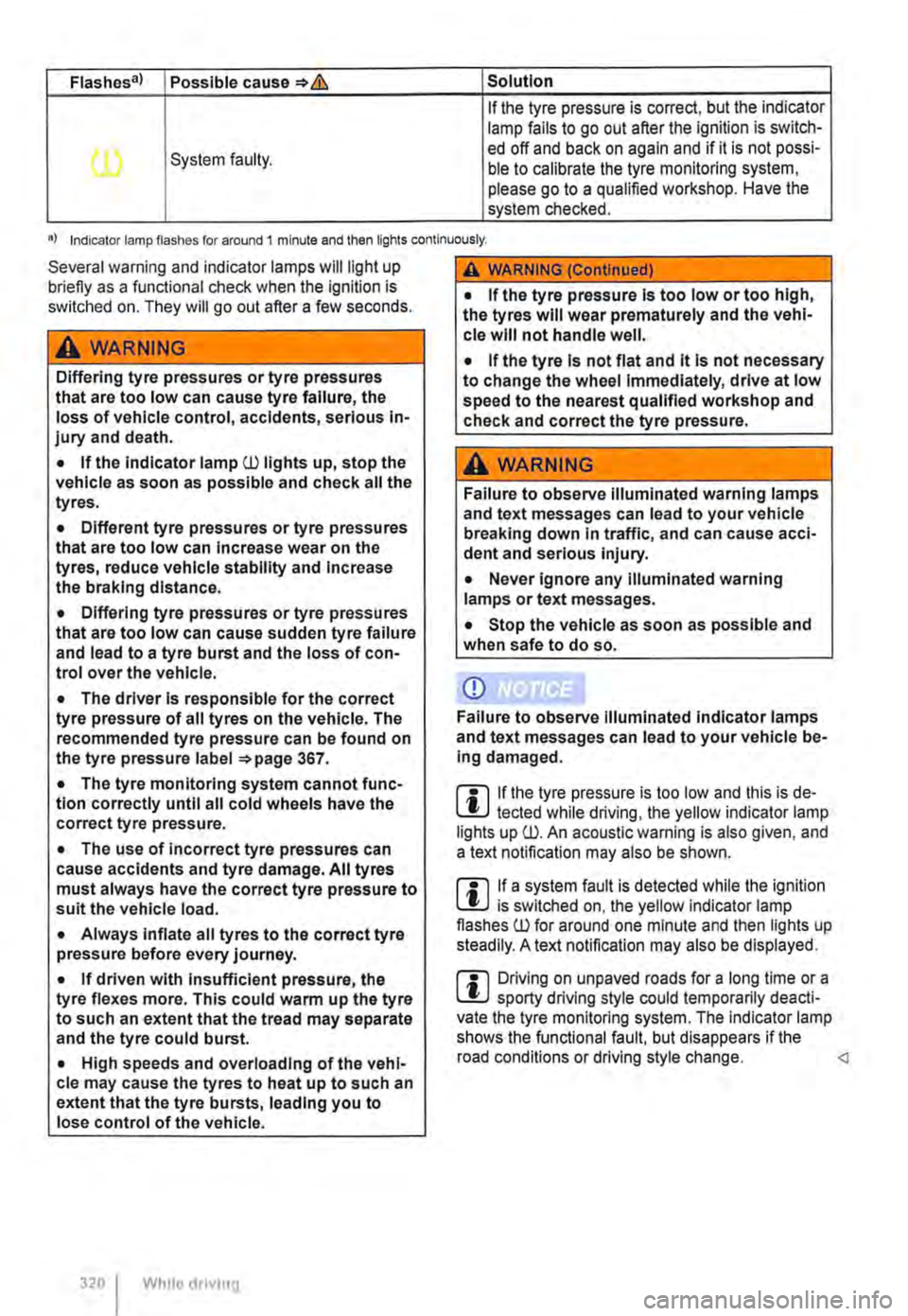
Flashes a) Possible cause*& Solution
If the tyre pressure is correct, but the indicator lamp fails to go out after the ignilion is switch-
(l) System faulty. ed off and back on again and if it is not possi-ble to calibrate the tyre monitoring system, please go to a qualified workshop. Have the system checked.
•I Indicator lamp flashes for around 1 minute and then lights continuously.
Several warning and indicator lamps will light up briefly as a functional check when the lgnilion is switched on. They will go out after a few seconds.
A WARNING
Differing tyre pressures or tyre pressures that are too low can cause tyre failure, the loss of vehicle control, accidents, serious in-jury and death.
• If the Indicator lamp (l) lights up, stop the vehicle as soon as possible and check all the tyres.
• Different tyre pressures or tyre pressures that are too low can Increase wear on the tyres, reduce vehicle stability and Increase the braking distance.
• Differing tyre pressures or tyre pressures that are too low can cause sudden tyre failure and lead to a tyre burst and the loss of con-trol over the vehicle.
• The driver Is responsible for the correct tyre pressure of all tyres on the vehicle. The recommended tyre pressure can be found on the tyre pressure label 367.
• The tyre monitoring system cannot func-tion correctly until all cold wheels have the correct tyre pressure.
• The use of Incorrect tyre pressures can cause accidents and tyre damage. All tyres must always have the correct tyre pressure to suit the vehicle load.
• Always Inflate all tyres to the correct tyre pressure before every journey.
• If driven with Insufficient pressure, the tyre flexes more. This could warm up the tyre to such an extent that the tread may separate and the tyre could burst.
• High speeds and overloading of the vehi-cle may cause the tyres to heat up to such an extent that the tyre bursts, leading you to lose control of the vehicle.
320 I Whllo drivmg
A WARNING (Continued)
• If the tyre pressure Is too low or too high, the tyres will wear prematurely and the vehl-cle will not handle well.
• If the tyre Is not flat and it Is not necessary to change the wheel immediately, drive at low speed to the nearest qualified workshop and check and correct the tyre pressure.
A WARNING
Failure to observe illuminated warning lamps and text messages can lead to your vehicle breaking down In traffic, and can cause acci-dent and serious injury.
• Never ignore any illuminated warning lamps or text messages.
• Stop the vehicle as soon as possible and when safe to do so.
CD
Failure to observe Illuminated Indicator lamps and text messages can lead to your vehicle be-Ing damaged.
m If the tyre pressure is too low and this is de-L!..) tected while driving, the yellow indicator lamp lights up (l). An acoustic warning is also given, and a text notification may also be shown.
m If a system fault is detected while the ignition L!..J is switched on, the yellow Indicator lamp flashes (l) for around one minute and then lights up steadily. A text notification may also be displayed.
m Driving on unpaved roads for a long time or a L!..J sporty driving style could temporarily deacti-vate the tyre monitoring system. The Indicator lamp shows the functional fault, but disappears if the road conditions or driving style change.
Page 321 of 486
Function and control
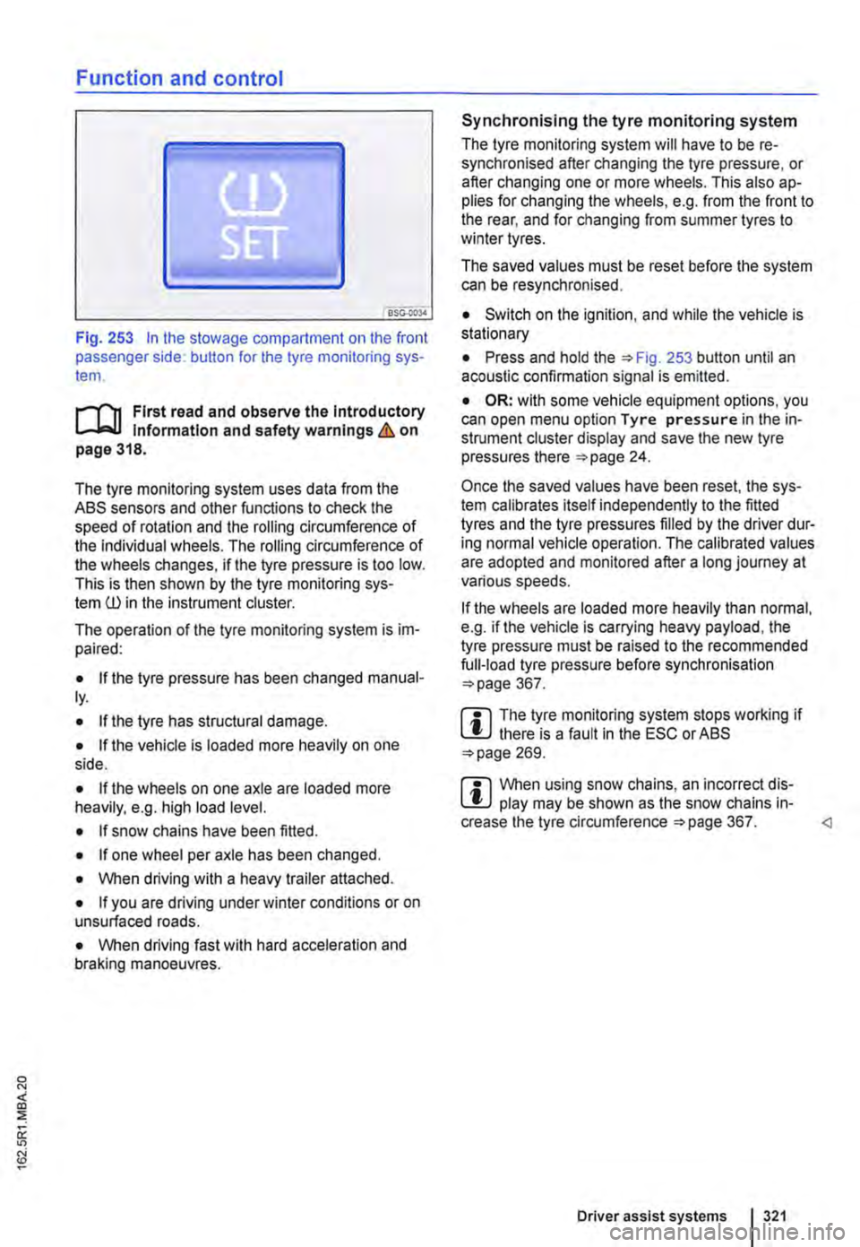
Fig. 253 In the stowage compartment on the front passenger side: button for the tyre monitoring sys-tem.
l"'"""f'n First read and observe the Introductory l.-J,.:,LL Information and safety warnings & on page 318.
The tyre monitoring system uses data from the ASS sensors and other functions to check the speed of rotation and the rolling circumference of the individual wheels. The rolling circumference of the wheels changes, if the tyre pressure is too low. This is then shown by the tyre monitoring sys-tem ill in the instrument cluster.
The operation of the tyre monitoring system is im-paired:
• If the tyre pressure has been changed manual-ly.
• If the tyre has structural damage.
• If the vehicle Is loaded more heavily on one side.
• If the wheels on one axle are loaded more heavily, e.g. high load level.
• If snow chains have been fitted.
• If one wheel per axle has been changed.
• When driving with a heavy trailer attached.
• If you are driving under winter conditions or on unsurfaced roads.
• When driving fast with hard acceleration and braking manoeuvres.
Synchronising the tyre monitoring system
The tyre monitoring system will have to be re-synchronised after changing the tyre pressure, or after changing one or more wheels. This also ap-plies for changing the wheels, e.g. from the front to the rear, and for changing from summer tyres to winter tyres.
The saved values must be reset before the system can be resynchronised.
• Switch on the ignition, and while the vehicle is stationary
• Press and hold the =>Fig. 253 button until an acoustic confirmation signal is emitted.
• OR: with some vehicle equipment options, you can open menu option Tyre pressure in the in-strument cluster display and save the new tyre pressures there =>page 24.
Once the saved values have been reset, the sys-tem calibrates itself independently to the fitted tyres and the tyre pressures filled by the driver dur-ing normal vehicle operation. The calibrated values are adopted and monitored after a long journey at various speeds.
If the wheels are loaded more heavily than normal, e.g. if the vehicle is carrying heavy payload, the tyre pressure must be raised to the recommended full-load tyre pressure before synchronisation =>page 367.
m The tyre monitoring system stops working if l!.J there is a fault in the ESC or ASS =>page 269.
m When using snow chains, an incorrect dis-l!.J play may be shown as the snow chains in-crease the tyre circumference =>page 367.
Page 359 of 486
Warning lamp and coolant temperature display
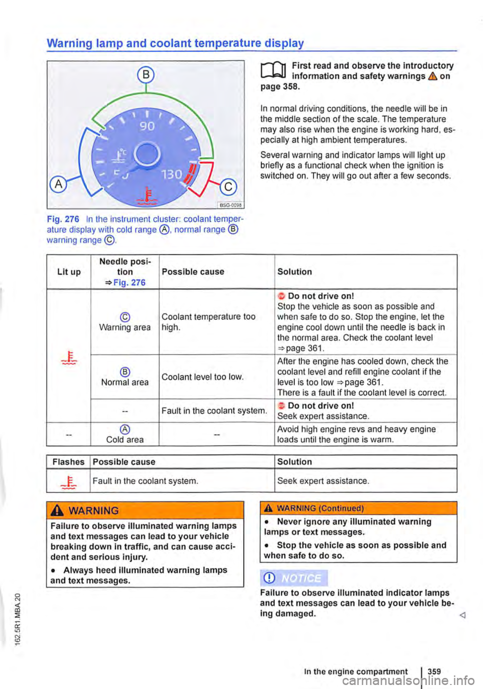
Fig. 276 In the instrument cluster: coolant temper-ature display with cold range @, normal range ® warning range @.
Needle posi-Lit up tion Possible cause =>Fig. 276
© Coolant temperature too Warning area high.
® Coolant level too low. Normal area
r-f"n First read and observe the introductory L,....J.:.lJ Information and safety warnings & on page 358.
In normal driving conditions, the needle will be in the middle section of the scale. The temperature may also rise when the engine is working hard, es-pecially at high ambient temperatures.
Several warning and indicator lamps will light up briefly as a functional check when the ignition is switched on. They will go out after a few seconds.
Solution
t Do not drive on! Stop the vehicle as soon as possible and when safe to do so. Stop the engine, let the engine cool down until the needle is back in the normal area. Check the coolant level =>page 361.
After the engine has cooled down, check the coolant level and refill engine coolant if the level is too low =>page 361. There is a fault if the coolant level is correct.
Fault in the coolant system. ·t Do not drive on! --Seek expert assistance.
--® Cold area --
Flashes Possible cause
Fault in the coolant system.
A WARNING
Failure to observe illuminated warning lamps and text messages can lead to your vehicle breaking down In traffic, and can cause acci-dent and serious injury.
• Always heed illuminated warning lamps and text messages.
Avoid high engine revs and heavy engine loads until the engine is warm.
Solution
Seek expert assistance.
A WARNING (Continued)
• Never ignore any illuminated warning lamps or text messages.
• Stop the vehicle as soon as possible and when safe to do so.
CD
Failure to observe illuminated indicator lamps and text messages can lead to your vehicle be-ing damaged.
Page 372 of 486
A WARNING (Continued)
• Check tyre pressures regularly, at least once a month, and before every long journey.
• All tyres must have the correct tyre pres-sure to suit the vehicle load.
• Never reduce excess pressure when the tyres are warm.
CD
• When attaching the tyre pressure gauge make sure that you do not position it at an an-gle to the valve shaft. This can damage the tyre valve.
Tread depth and wear indicators
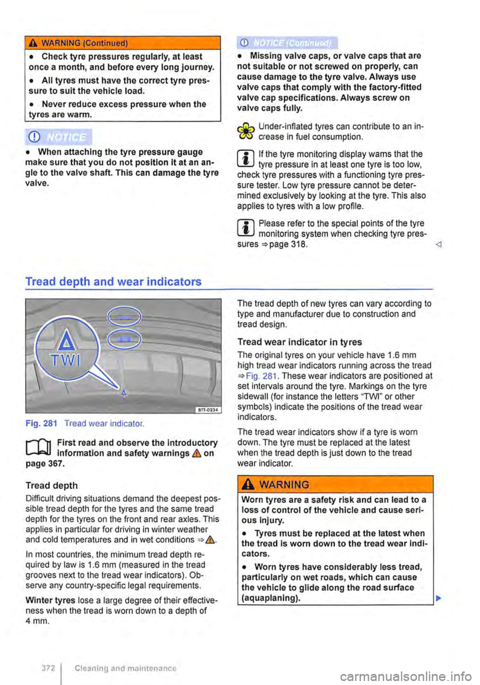
Fig. 281 Tread wear indicator.
r-fl1 First read and observe the Introductory L-.lo:::.l.l Information and safety warnings & on page 367.
Tread depth
Difficult driving situations demand the deepest pos-sible tread depth for the tyres and the same tread depth for the tyres on the front and rear axles. This applies in particular for driving in winter weather and cold temperatures and in wet conditions=>&.
In most countries, the minimum tread depth re-quired by law is 1.6 mm (measured in the tread grooves next to the tread wear indicators). Ob-serve any country-specific legal requirements.
Winter tyres lose a large degree of their effective-ness when the tread is worn down to a depth of 4mm.
3721 Cleaning and maintenance
CD
• Missing valve caps, or valve caps that are not suitable or not screwed on properly, can cause damage to the tyre valve. Always use valve caps that comply with the factory-fitted valve cap specifications. Always screw on valve caps fully.
Under-infiated tyres can contribute to an in-I!IS crease in fuel consumption.
m If the tyre monitoring display warns that the W tyre pressure in at least one tyre is too low, check tyre pressures with a functioning tyre pres-sure tester. Low tyre pressure cannot be deter-mined exclusively by looking at the tyre. This also applies to tyres with a low profile.
m Please refer to the special points of the tyre W monitoring system when checking tyre pres-sures =>page 318.
Tread wear indicator in tyres
The original tyres on your vehicle have 1.6 mm high tread wear indicators running across the tread =>Fig. 281. These wear indicators are positioned at set intervals around the tyre. Markings on the tyre sidewall (for instance the letters "TWI" or other symbols) indicate the positions of the tread wear indicators.
The tread wear indicators show if a tyre is worn down. The tyre must be replaced at the latest when the tread depth is just down to the tread wear indicator.
A WARNING
Worn tyres are a safety risk and can lead to a loss of control of the vehicle and cause seri-ous Injury.
• Tyres must be replaced at the latest when the tread Is worn down to the tread wear Indi-cators.
• Worn tyres have considerably less tread, particularly on wet roads, which can cause the vehicle to glide along the road surface (aquaplaning).
Page 376 of 486
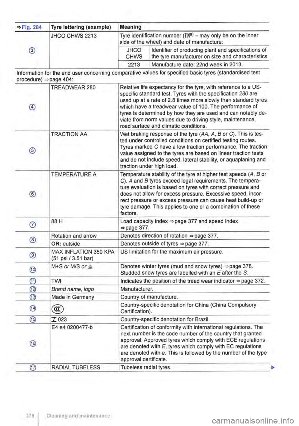
=>Fig. 284 Tyre lettering (example) I Meaning
JHCO CHWS 2213 Tyre identification number (TINa)-may only be on the inner side of the wheel) and date of manufacture:
® JHCO Identifier of producing plant and specifications of CHWS the tyre manufacturer on size and characteristics
2213 Manufacture date: 22nd week in 2013.
Information for the end user concernmg comparat1ve values for spec1fied bas1c tyres (standardised test procedure) =>page 404·
TREADWEAR 280 Relative life expectancy for the tyre, with reference to a US-specific standard test. Tyres with the specification 280 are used up at a rate of 2.8 times more slowly than standard tyres
@ which have a treadwear value of 100. The performance of tyres is determined by how they are used and can notably de-viate from norm values due to driving style, maintenance, road surface and climatic conditions.
TRACTION AA Wet braking response of the tyre (AA, A, B or C). This is tes-led under controlled conditions on certified testing routes.
® Tyres marked C have a low traction performance. The traction value assigned to the tyres are based on linear traction tests and do not include speed, lateral stability, or aquaplaning and traction under high load.
TEMPERATURE A Temperature stability of the tyre at higher test speeds (A, B or C). A and B tyres exceed legal requirements. The tempera-tu re evaluation is based on tyres with correct pressure and
® does not allow for excess pressure. Excessive speed, incor-reel pressure or excess pressure can cause heat build-up or tyre damage. This applies to one or a combination of these factors.
0 88 H Load capacity index ::.page 377 and speed index ::.page 377.
® Rotation and arrow Denotes direction of rotation ::.page 377.
OR: outside Denotes outside of tyres ::.page 377.
® MAX INFLATION 350 KPA US limitation for the maximum air pressure. (51 psi /3.51 bar)
® M+S or M/S or & Denotes winter tyres (mud and snow tyres) ::.page 378. Studded snow tyres are labelled with an E after the S.
® TWI Indicates the position of the tread wear indicator ::.page 372.
@ Brand name. logo Manufacturer.
@ Made in Germany Country of manufacture.
@> @ Country-specific denotation for China (China Compulsory Certification).
® :r 023 Country-specific denotation for Brazil.
E4 e4 0200477-b Certification of conformity with international regulations. The next number is the code number of the country that granted
® approval. Approved tyres which comply with ECE regulations are denoted with E. tyres which comply with EC regulations are denoted with e. This is followed by the number of the type approval certificate.
@ RADIAL TUBELESS Tubeless radial tyres.
376 I Cleaning and maintenance
Page 378 of 486
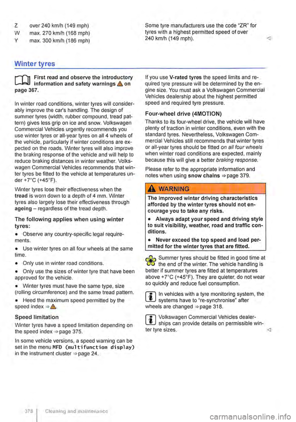
z
w y
over 240 km/h (149 mph)
max. 270 kmlh (168 mph)
max. 300 kmlh (186 mph)
Winter tyres
r-f'n First read and observe the introductory L-J,::JJ information and safety warnings & on page 367.
In winter road conditions, winter tyres will consider-ably improve the car's handling. The design of summer tyres (width, rubber compound, tread pat-tern) gives less grip on ice and snow. Volkswagen Commercial Vehicles urgently recommends you use winter tyres or all-year tyres on all 4 wheels of the vehicle, particularly if winter conditions are ex-pected on the roads. Winter tyres will also improve the braking response of the vehicle and will help to reduce braking distances in winter weather. Volks-wagen Commercial Vehicles recommends that win-ter tyres be fitted to the vehicle at temperatures un-der+ 7•c (+45°F).
Winter tyres lose their effectiveness when the tread is worn down to a depth of 4 mm. Winter tyres also largely lose their effectiveness through ageing-regardless of the tread depth.
The following applies when using winter tyres:
• Observe any country-specific legal require-ments.
• Use winter tyres on all four wheels at the same time.
• Only use in winter road conditions.
• Only use the sizes of winter tyre that have been approved for the vehicle.
• Winter tyres must have the same type, size (rolling circumference) and the same tread pattern.
• Heed the maximum speed permitted by the speed index => &.
Speed limitation
Winter tyres have a speed limitation depending on the speed index =>page 375.
In some vehicle versions, a speed warning can be set in the menu MFD (multi function display) in the instrument cluster =>page 24.
378 I Cleaning and maintenance
Some tyre manufacturers use the code "ZR" for tyres with a highest permitted speed of over 240 km/h (149 mph).
If you use V-rated tyres the speed limits and re-quired tyre pressure will be determined by the en-gine size. You must ask a Volkswagen Commercial Vehicles dealership about the highest permitted speed and required tyre pressure.
Four-wheel drive (4MOTION)
Thanks to its four-wheel drive, the vehicle will have plenty of traction in winter conditions, even with the standard tyres. Nevertheless, Volkswagen Com-mercial Vehicles still recommends that winter tyres or all-year tyres should be fitted on all four wheels when winter road conditions are expected, mainly because this will give a better braking response.
Please refer to the appropriate information and notes when using snow chains =>page 379.
A WARNING
The Improved winter driving characteristics afforded by the winter tyres should not en-courage you to take any risks.
• Always adapt your speed and driving style to suit visibility, weather, road and traffic con-ditions.
• Never exceed the top speed and load per-mitted for the winter tyres that are fitted.
r:Q;-.. Summer tyres should be fitted in good time at the end of the winter. The vehicle handling is better if summer tyres are fitted at temperatures above +7•c (+45.F). They are quieter, do not wear so quickly and reduce fuel consumption.
m In vehicles with a tyre monitoring system, the l!.J systems have to "re-synchronise" after wheels are changed =>page 318.
m Volkswagen Commercial Vehicles dealer-l!.J ships can provide details on permissible win-
Page 379 of 486
Snow chains
r-"f"'n First read and observe the introductory L-J=.IJ information and safety warnings & on page 367.
Please heed legislation and also the permitted speed when driving your vehicle with snow chains.
In winter conditions, snow chains will not only im-prove acceleration, but also braking response.
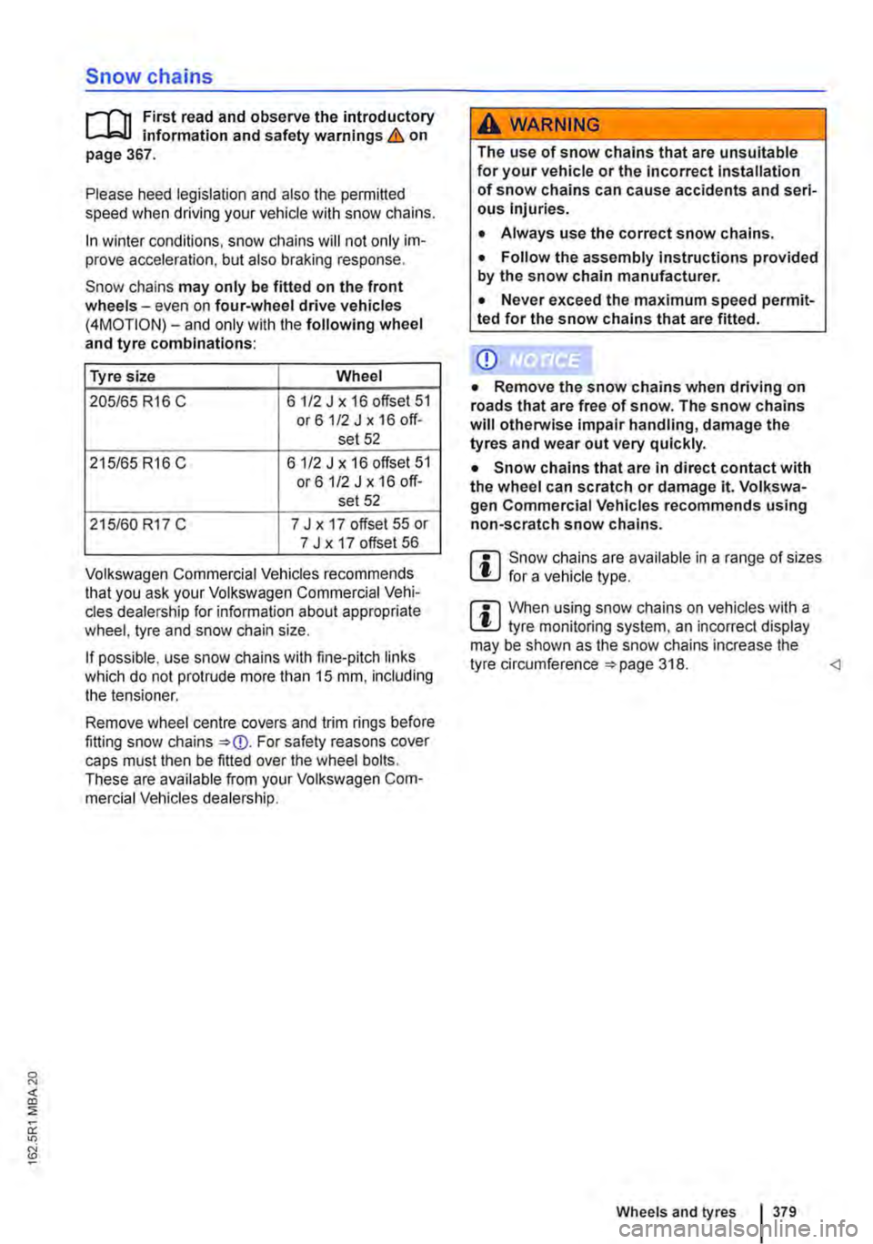
Snow chains may only be fitted on the front wheels-even on four-wheel drive vehicles (4MOTION)-and only with the following wheel and tyre combinations:
Tyre size Wheel
205/65 R16 C 6 1/2 J x 16 offset 51 or61/2Jx16off-set 52
215/65 R16 C 6 112 J x 16 offset 51 or61/2 J x 16 off-set 52
215/60 R17 C 7 J x 17 offset 55 or 7 J x 17 offset 56
Volkswagen Commercial Vehicles recommends that you ask your Volkswagen Commercial Vehi-cles dealership for information about appropriate wheel, tyre and snow chain size.
If possible, use snow chains with fine-pitch links which do not protrude more than 15 mm, including the tensioner.
Remove wheel centre covers and trim rings before fitting snow chains For safety reasons cover caps must then be fitted over the wheel bolts. These are available from your Volkswagen Com-mercial Vehicles dealership.
A WARNING
The use of snow chains that are unsuitable for your vehicle or the incorrect installation of snow chains can cause accidents and seri-ous Injuries.
• Always use the correct snow chains.
• Follow the assembly instructions provided by the snow chain manufacturer.
• Never exceed the maximum speed permit-ted for the snow chains that are fitted.
Q)
• Remove the snow chains when driving on roads that are free of snow. The snow chains will otherwise impair handling, damage the tyres and wear out very quickly.
• Snow chains that are in direct contact with the wheel can scratch or damage it. Volkswa-gen Commercial Vehicles recommends using non-scratch snow chains.
m Snow chains are available in a range of sizes l!:.J for a vehicle type.
m When using snow chains on vehicles with a l!:.J tyre monitoring system, an incorrect display may be shown as the snow chains increase the tyre circumference 318.