fold seats VOLKSWAGEN TRANSPORTER 2014 Owners Manual
[x] Cancel search | Manufacturer: VOLKSWAGEN, Model Year: 2014, Model line: TRANSPORTER, Model: VOLKSWAGEN TRANSPORTER 2014Pages: 486, PDF Size: 69.28 MB
Page 73 of 486
Single seats
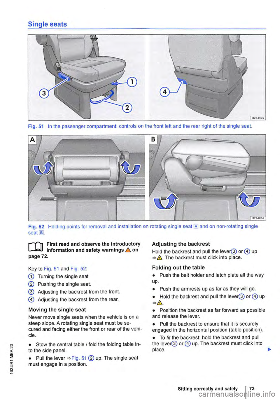
Fig. 51 In the passenger compartment: controls on the front left and the rear right of the single seat.
Fig. 52 Holding points for removal and installation on rotating single seat .A and on non-rotating single seats .
....-m First read and observe the introductory L.-.lo:.U Information and safety warnings & on page 72.
Key to Fig. 51 and Fig. 52:
CD Turning the single seat
@ Pushing the single seat.
@ Adjusting the backrest from the front.
0 Adjusting the backrest from the rear.
Moving the single seat
Never move single seats when the vehicle is on a steep slope. A rotating single seat must be se-cured and facing either the front or rear of the vehi-cle.
• Stow the central table I fold the folding table in-to the side panel.
• Pull the lever 51@ up. The single seat must engage in a position.
Adjusting the backrest
Hold the backrest and pull the lever@ or 0 up ""'&.The backrest must click into place.
Folding out the table
• Push the belt holder and latch plate all the way up.
• Push the armrests up as far as they will go.
• Hold the backrest and pull the lever@ or 0 up
• Position the backrest as far forward as possible and release the lever.
• Pull the backrest to ensure that it is securely engaged in the horizontal position (table position).
• To fit the backrest: hold the backrest and pull the lever@ or 0 up. The backrest must click into place. 11>
Sitting correctly and safely
Page 74 of 486
Turning the single seat
• To ensure enough room for turning: place the backrest in an upright position. move the central table and return it to its basic position. Secure the vehicle against rolling away and set the handbrake lever to the lowest position.
• Pull the lever(D to the side and turn the seat slightly in the required direction.
• Release lever and turn the seat further. The single seat must engage in a position.
Removing a single seat
• Push the central table forwards I fold the folding table into the side panel.
• If necessary slide the front seats forwards.
• If necessary, move the backrest of the front seats to the upright position.
• Remove the protective covers from the seat rails 133.
• Removing the head restraint
• Fold out the table.
• For rotating single seat: turn the single seat through go• so that the backrest points in the direc-tion of the open sliding door.
• Push the single seat forwards in the seat rails to the point where the seat feet can be lifted out of the slots.
• For rotating single seat: lift the seat at the armrests near the centre of rotation (arrows).
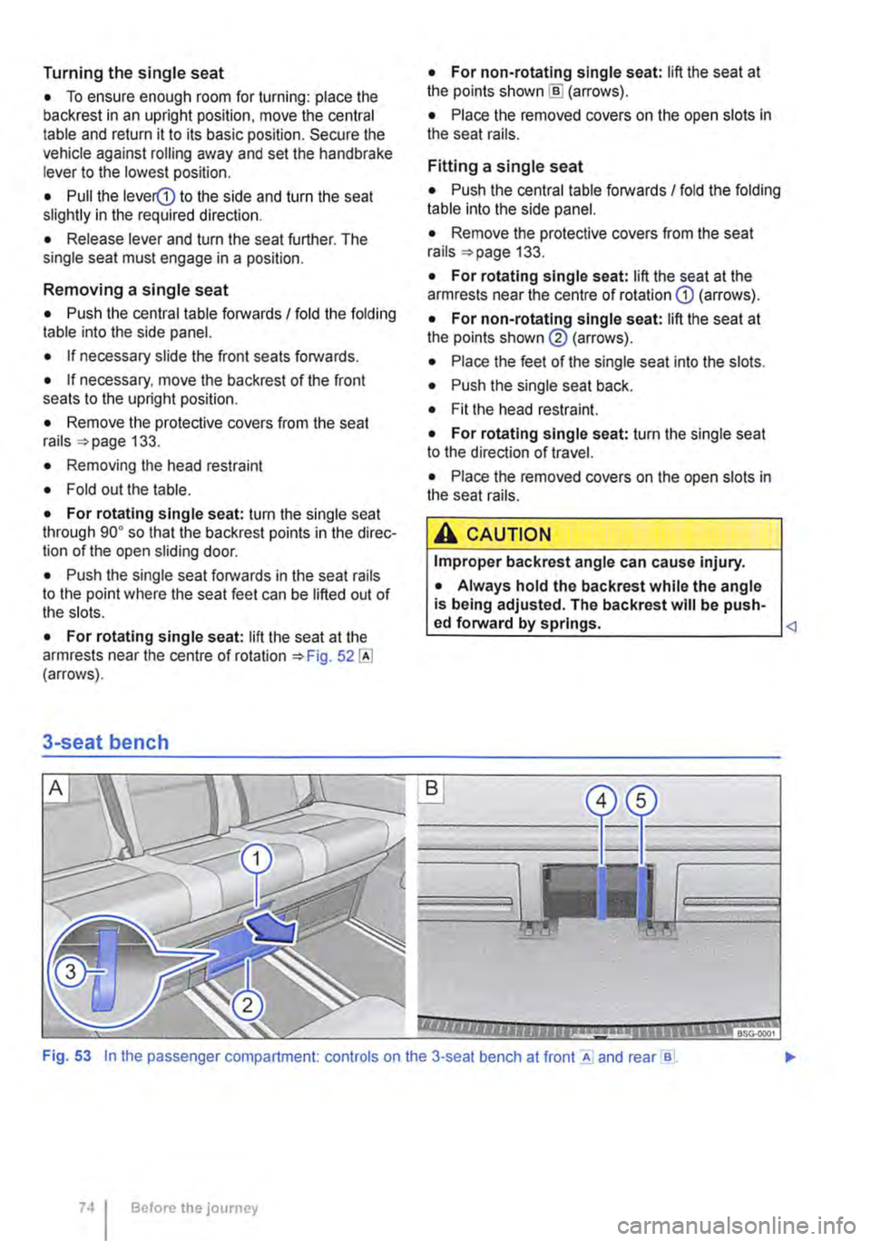
3-seat bench
• For non-rotating single seat: lift the seat at the points shown [ID (arrows).
• Place the removed covers on the open slots in the seat rails.
Fitting a single seat
• Push the central table forwards I fold the folding table into the side panel.
• Remove the protective covers from the seat rails 133.
• For rotating single seat: lift the seat at the armrests near the centre of rotation G) (arrows).
• For non-rotating single seat: lift the seat at the points shown@ (arrows).
• Place the feet of the single seat into the slots.
• Push the single seat back.
• Fit the head restraint.
• For rotating single seat: turn the single seat to the direction of travel.
• Place the removed covers on the open slots in the seat rails.
A CAUTION
Improper backrest angle can cause injury.
• Always hold the backrest while the angle is being adjusted. The backrest will be push-ed forward by springs.
Before the journey
Page 75 of 486
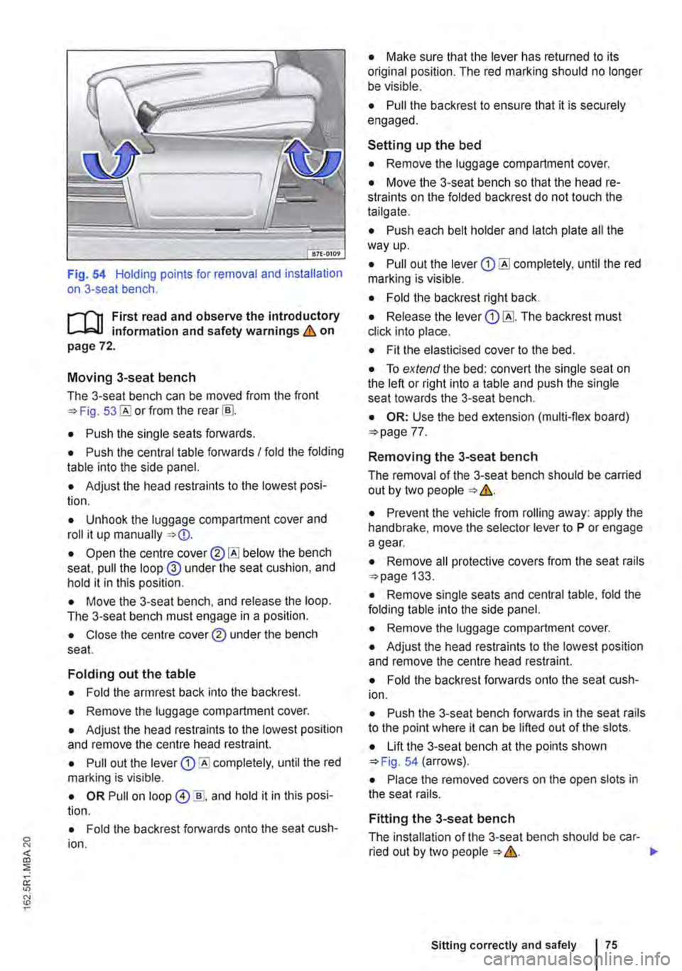
Fig. 54 Holding points for removal and installation on 3-seat bench.
,....-m First read and observe the introductory L-W.I information and safety warnings & on page 72.
Moving 3-seat bench
The 3-seat bench can be moved from the front =>Fig. or from the rear [ru.
• Push the single seats forwards.
• Push the central table forwards I fold the folding table into the side panel.
• Adjust the head restraints to the lowest posi-tion.
• Unhook the luggage compartment cover and roll it up manually =>
• Move the 3-seat bench, and release the loop. The 3-seat bench must engage in a position.
• Close the centre cover® under the bench seat.
Folding out the table
• Fold the armrest back into the backrest.
• Remove the luggage compartment cover.
• Adjust the head restraints to the lowest position and remove the centre head restraint.
• Pull out the lever Q) completely, until the red marking is visible.
• OR Pull on loop @ ]], and hold it in this posi· lion.
• Fold the backrest forwards onto the seat cush· ion.
• Make sure that the lever has returned to its original position. The red marking should no longer be visible.
• Pull the backrest to ensure that it is securely engaged.
Setting up the bed
• Remove the luggage compartment cover.
• Move the 3-seat bench so that the head re· straints on the folded backrest do not touch the tailgate.
• Push each belt holder and latch plate all the way up.
• Pull out the lever Q) until the red marking is visible.
• Fold the backrest right back.
• Release the lever Q) The backrest must click into place.
• Fit the elasticised cover to the bed.
• To extend the bed: convert the single seat on the left or right into a table and push the single seat towards the 3-seat bench.
• OR: Use the bed extension (multi-flex board) =>page 77.
Removing the 3-seat bench
The removal of the 3-seat bench should be carried out by two people => &.
• Prevent the vehicle from rolling away: apply the handbrake, move the selector lever to P or engage a gear.
• Remove all protective covers from the seat rails =>page 133.
• Remove single seats and central table, fold the folding table into the side panel.
• Remove the luggage compartment cover.
• Adjust the head restraints to the lowest position and remove the centre head restraint.
• Fold the backrest forwards onto the seat cush-ion.
• Push the 3-seat bench forwards in the seat rails to the point where it can be lifted out of the slots.
• Lift the 3-seat bench at the points shown =>Fig. 54 (arrows).
• Place the removed covers on the open slots in the seat rails.
Fitting the 3-seat bench
The installation of the 3-seat bench should be car-ried out by two people => &. .,.
Sitting correctly and safely
Page 77 of 486
Bed extension (multi-flex board)
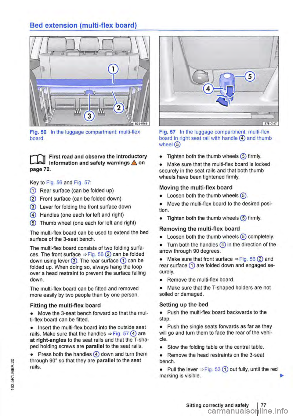
Fig. 56 In the luggage compartment: multi-flex board.
.--m First read and observe the Introductory L-.J,..U lnfonmatlon and safety warnings & on page 72.
Key to Fig. 56 and Fig. 57:
CD Rear surface (can be folded up)
@ Front surface (can be folded down)
@ Lever for folding the front surface down
@ Handles (one each for left and right)
® Thumb wheel (one each for left and right)
The multi-flex board can be used to extend the bed surface of the 3-seat bench.
The multi-flex board consists of two folding surfa-ces. The front surface =>Fig. 56@ can be folded down using lever@. The rear surface CD can be folded up. When doing so, always hang the loop over a head restraint to prevent the surface falling down.
The multi-flex board can be fitted and removed more easily by two people than by one person.
Fitting the multi-flex board
• Move the 3-seat bench forward so that the mul-ti-flex board can be fitted.
• Insert the multi-flex board into the outside seat rails. Make sure that the handles =>Fig. 57@ are at right-angles to the seat rails and that the T-sha-ped holding screws are parallel to the seat rails.
• Press both the handles@ down and turn them through go• so that they are parallel to the seat rails.
Fig. 57 In the luggage compartment: multi-flex board in right seat rail with handle @ and thumb wheel@
• Tighten both the thumb wheels® firmly.
• Make sure that the multi-flex board is locked securely in the seat rails and that both thumb wheels have been tightened firmly.
Moving the multi-flex board
• Loosen both the thumb wheels @.
• Move the multi-flex board to the desired posi-tion.
• Tighten both the thumb wheels® firmly.
Removing the multi-flex board
• Loosen both the thumb wheels® completely.
• Turn both the handles@ in the direction of the arrow through 90 degrees.
• Make sure that front surface =>Fig. 56@ and rear surface CD are folded down and engaged se-curely.
• Remove the multi-flex board.
• Make sure that the T-shaped holders are not soiled or damaged.
Setting up the bed
• Push the multi-flex board backwards to the stop.
• Push the single seats forwards as far as they will go and turn them to face the rear of the vehi-cle.
• Stow the folding table or the central table.
• Remove the head restraints on the 3-seat bench.
• Pull the lever =>Fig. 53 CD out fully, until the red marking is visible. 11>
Sitting correctly and safely
Page 78 of 486
• Fold the backrest of the 3-seat bench com-pletely forwards onto the seat cushion.
• Open the centre cover 53®@ below the bench seat, pull the loop @ under the seat cushion, and hold it in this position.
• Push the 3-seat bench forward to the single seats, and release the loop. The 3-seat bench must contact the seat cushions of the single seats.
• Pull the lever 53 CD out fully, until the red marking is visible.
• Fold the backrest of the 3-seat bench com-pletely backwards.
• Make sure that the lever has returned to its original position. The red marking should no longer be visible.
• Fold up the front surface 56® of the multi-flex board.
• Place the supplied mattress on the multi-flex board.
• Fit the elasticised cover to the bed.
A WARNING
Objects that are not secured, or are secured incorrectly, can cause serious injuries in the event of a sudden driving or braking manoeu-vre or accident.
Centre armrest
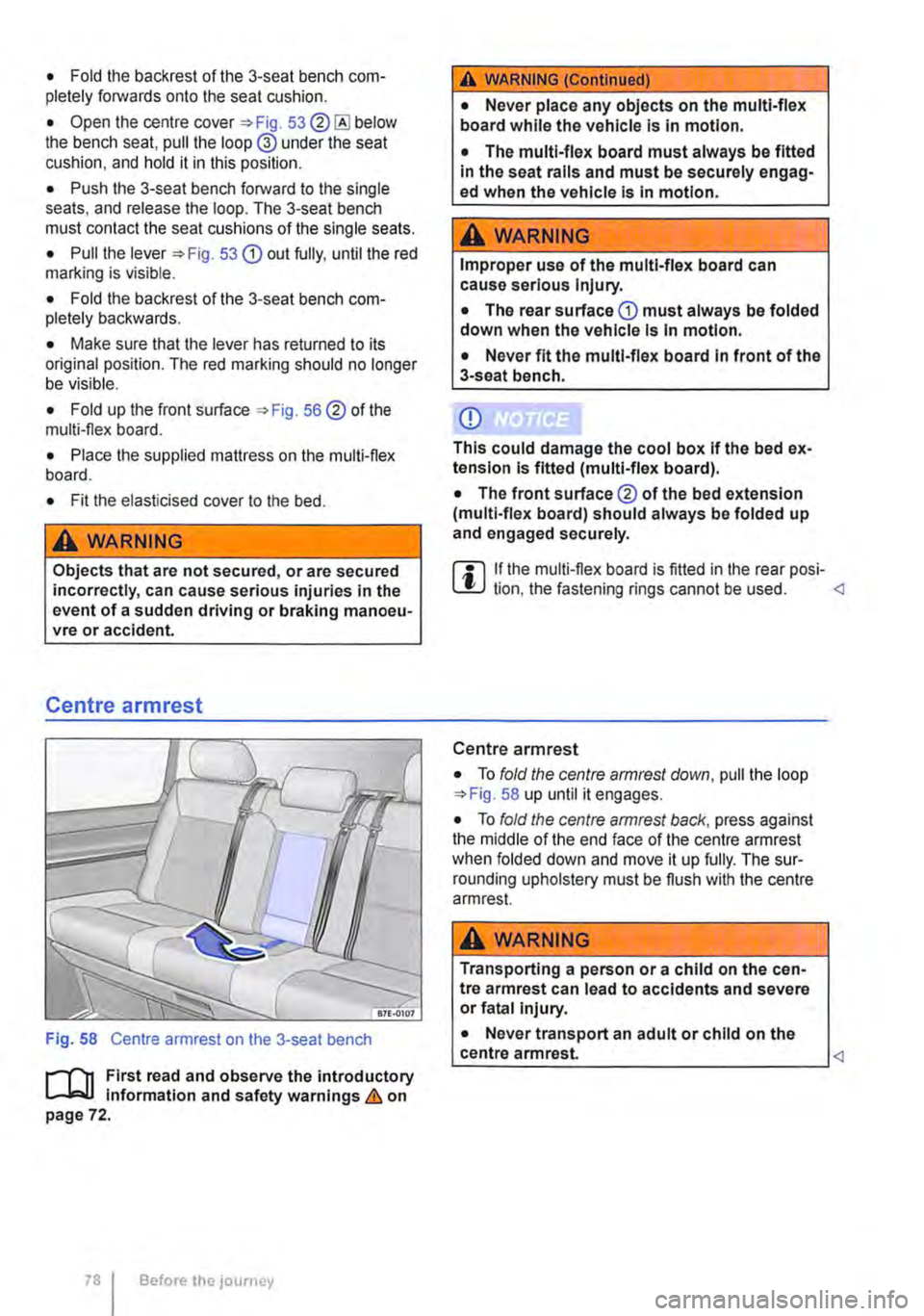
Fig. 58 Centre armrest on the 3-seat bench
1"'1'11 First read and observe the introductory l.-J,::.IJ information and safety warnings & on page 72.
78 Before the journey
A WARNING (Continued)
• Never place any objects on the multi-flex board while the vehicle Is In motion.
• The multi-flex board must always be fitted in the seat rails and must be securely engag-ed when the vehicle Is In motion.
A WARNING
Improper use of the multi-flex board can cause serious Injury.
• The rear surface CD must always be folded down when the vehicle Is In motion.
• Never fit the multi-flex board In front of the 3-seat bench.
Q)
This could damage the cool box If the bed ex-tension Is fitted (multi-flex board).
• The front surface® of the bed extension (multi-flex board) should always be folded up and engaged securely.
m If the multi-flex board is fitted in the rear posi-L!..J lion. the fastening rings cannot be used.
• To fold the centre armrest down, pull the loop 58 up until it engages.
• To fold the centre armrest back, press against the middle of the end face of the centre armrest when folded down and move it up fully. The sur-rounding upholstery must be flush with the centre armrest.
A WARNING
Transporting a person or a child on the cen-tre armrest can lead to accidents and severe or fatal Injury.
• Never transport an adult or child on the
__
Page 93 of 486
A DANGE;R (Continued) --
• No other people, animals or objects may be carried between the occupants of the front seats and the alrbag deployment zone. Make sure that children and passengers also keep to this rule.
• Do not attach any objects, e.g. mobile nav-igation devices, to the windscreen above the front alrbag on the front passenger side.
• Do not cover or stick anything on the steering wheel hub or the soft plastic surface of the alrbag unit In the dash panel on the front passenger side, and do not modify them In any way.
A WARNING
The front alrbags are deployed In front of the steering wheel "*Fig. 71 and dash panel '*Fig. 72.
• When driving, always hold the steering wheel with both hands on the outside of the ring at the 9 o'clock and 3 o'clock positions.
• Adjust the driver seat so that there is at least 25 cm between your breastbone and the hub of the steering wheel. Contact a qualified workshop if your physical build makes this Impracticable.
• Adjust the front passenger seat so that the distance between the passenger and the
__ ____
Switching the front passenger front airbag on and off manually using the
key-operated switch
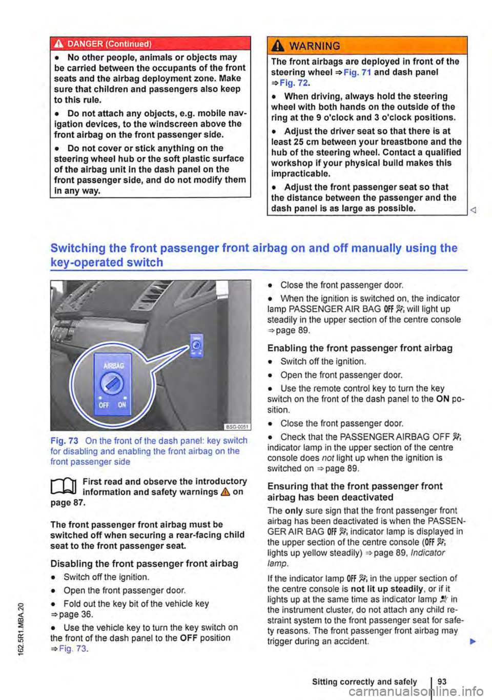
Fig. 73 On the front of the dash panel: key switch for disabling and enabling the front airbag on the front passenger side
l""'rn First read and observe the introductory L-J,::.U information and safety warnings&. on page 87.
The front passenger front airbag must be switched off when securing a rear-facing child seat to the front passenger seat.
Disabling the front passenger front airbag
• Switch off the ignition.
• Open the front passenger door.
• Fold out the key bit of the vehicle key o>page 36.
• Use the vehicle key to turn the key switch on the front of the dash panel to the OFF position o> Fig. 73.
• Close the front passenger door.
• When the ignition is switched on, the indicator lamp PASSENGER AIR BAG will light up steadily in the upper section of the centre console o> page 89.
Enabling the front passenger front airbag
• Switch off the ignition.
• Open the front passenger door.
• Use the remote control key to turn the key switch on the front of the dash panel to the ON po-sition.
• Close the front passenger door.
• Check that the PASSENGER AIRBAG OFF indicator lamp in the upper section of the centre console does not light up when the Ignition is switched on =>page 89.
Ensuring that the front passenger front airbag has been deactivated
The only sure sign that the front passenger front airbag has been deactivated is when the PASSEN-GER AIR BAG indicator lamp is displayed in the upper section of the centre console (OFF lights up yellow steadily) =>page 89, Indicator lamp.
If the indicator lamp OFF )!(; in the upper section of the centre console is not lit up steadily, or if it lights up at the same time as indicator lamp in the instrument cluster, do not attach any child re-straint system to the front passenger seat for safe-ty reasons. The front passenger front airbag may trigger during an accident.
Sitting correctly and safely
Page 101 of 486
Installing child seats with ISOFIX ISOFIX/i-
Size
The location of the ISO FIX anchor points is shown either by a symbol or by a label marked "ISOFIX" 79.
• Observe the warnings 97, Basic infor-mation on fitting and using child seats.
• Push the attachment arms on the child seat into the ISOFIX anchor points 79 as shown by the arrows. The child seat must click and audibly securely into place.
• Pull on both sides of the child seat to check whether the seat has clicked properly into place.
• If the child seat is fitted with a support foot, the foot must sit firmly on the floor of the vehicle.
Using insert guides
If the child seat anchor points are not directly ac-cessible, insert guides make fitting and removing the child seat easier. First attach the insert guides to the anchor points. Then secure the child seat as per the installation guide.
CD
Avoid damage to the upholstery and seat cush-ions caused by the Insert guides.
• Always pull the insert guides off the anchor points before folding the rear seat forward, or when removing the child seat.
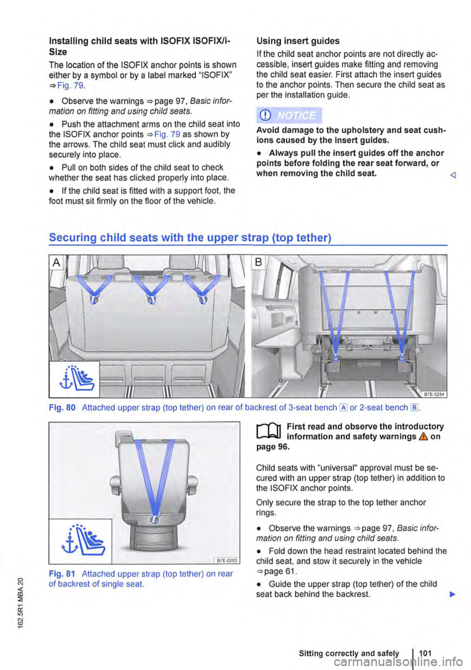
Fig. 80 Attached upper strap (top tether) on rear of backrest of 3-seat or 2-seat bench [ID.
87E-0783
Fig. 81 Attached upper strap (top tether) on rear of backrest of single seat.
r-1'11 First read and observe the Introductory L-lcJ.I Information and safety warnings & on page 96.
Child seats with "universal" approval must be se-cured with an upper strap (top tether) in addition to the ISOFIX anchor points.
Only secure the strap to the top tether anchor rings.
• Observe the warnings 97, Basic infor-mation on fitting and using child seats.
• Fold down the head restraint located behind the child seat, and stow it securely in the vehicle 61.
• Guide the upper strap (top tether) of the child seat back behind the backrest. )I>
Sitting correctly and safely 1101
Page 102 of 486
• Push the attachment arms on the child seat into the ISOFIX anchor points 79 as shown by the arrows. The child seat must click and audibly securely into place.
• Fasten the upper strap (top tether) into the cor-responding retaining rings 80 or 81.
• Stretch the belt so that the child seat is posi-tioned high on the rear seat backrest.
• After the child seat has been removed, fold up the head restraint or install it accordingly.
Securing child seats with a seat belt
r-111 First read and observe the Introductory L--lo:oU information and safety warnings & on page 96.
If you want to fit a child seat from the "universal" (u) approval category in your vehicle. you must first ensure that it is approved for the seat position in question. Important information is given on the or-ange ECE approval label on the child seat.
Group Child's weight
Group 0 up to 10 kg
Group 0+ up to 13 kg
Group 1 9 to 18 kg
Group 2 15 to 25 kg
Group 3 22 to 36 kg
Securing a child seat using the seat belt
• Observe the warnings 97, Basic infor-mation on fitting and using child seals.
• The seat belt height adjuster must be at the highest setting.
• Fasten the seat belt or guide it through the child seat as described in the child seat manufacturer's instructions.
Integrated child seat
o::n Introduction
This chapter contains information on the following subjects:
Folding integrated child seat up and down ... 104
Seat belt routing for an integrated child seat . 105
102 Before the journey
A WARNING
Only secure the strap to the top tether anchor rings. Failure to do this could lead to severe Injuries.
• Each anchor ring can hold only one child seat restraining strap.
Front passenger seat Seats In the passenger compartment (all)
u u
u u
u u
u u
u u
• Ensure that the seat belt is not twisted.
• Insert the latch plate into the buckle for the ap-propriate seat and push it down until it locks se-curely with a click.
The following table lists how the integrated child seat can be used. .,..
Page 137 of 486

n11 First read and observe the introductory l-J=,IJ information and safety warnings & on page 133.
The net partition can prevent objects in the lug-gage compartment entering the passenger com-partment.
The net partition can be fitted behind the front seats or behind the 3-seat bench.
Key to Fig. 111:
® Cross pieces with joints which lock into place
Preparing the net partition for fitting
• Take the net partition out of its plastic bag and unroll it fully.
• Fold out all the side rods fully, until you hear a "clicking• noise.
Fitting the net partition
• Make sure that the sewn-in instructions label is pointing to the rear.
• Hook the net partition up onto the left-hand side
• Push the rod together to hook the net partition onto the right-hand side.
• Pull the net partition to check that it has engag-ed securely in the retainers in the headliner.
• On the left and right sides. pull the strap down on the loop G) until you can insert the T-shaped holder into the outer seat rails.
• Turn each of the T-shaped holders through 90° so that they are positioned across the seat rails @.
• Make sure that the net partition is vertical and securely fitted in the seat rails.
Roof carrier
COl Introduction
This chapter contains information on the following subjects:
Attaching the mounts and roof carrier . . . . . . . 138 Loading the roof carrier . . . . . . . . . . . . . . . . . . . 139
Removing the net partition
• Slacken off the straps by pulling loop
• Push the net partition on one side slightly to the inside of the vehicle and lift it out of the upper re-tainer.
• Press the release button 111 ® in the joint of each cross piece and fold the cross pieces together.
• Roll up the net partition and stow it in its plastic bag.
• Stow the plastic bag securely in the vehicle.
A WARNING
Always use the net partition carefully, observ-Ing the Instructions. Risk of injury.
• The net partition is secured properly in the roof only if the T-shaped holders are securely fitted Into the retainers.
• The net partition is fitted correctly in the seat rails only if the T-shaped retainers are at right-angles to the seat rails and correctly en-gaged.
• The T-shaped holders must never be fitted close to the removable covers on the seat rails.
• Heavy, pointed or sharp items which are not stowed securely can cause Injury in the event of sudden braking manoeuvres or acci-dents. This may also happen when the net partition is fitted correctly.
• Vehicle occupants must not travel behind a fitted safety net.
• When it is no longer being used.
• When the vehicle is driving through a car wash.
• When the vehicle height exceeds the required clearance height, e.g. in a garage. .,.
Transporting items 1137
Page 157 of 486
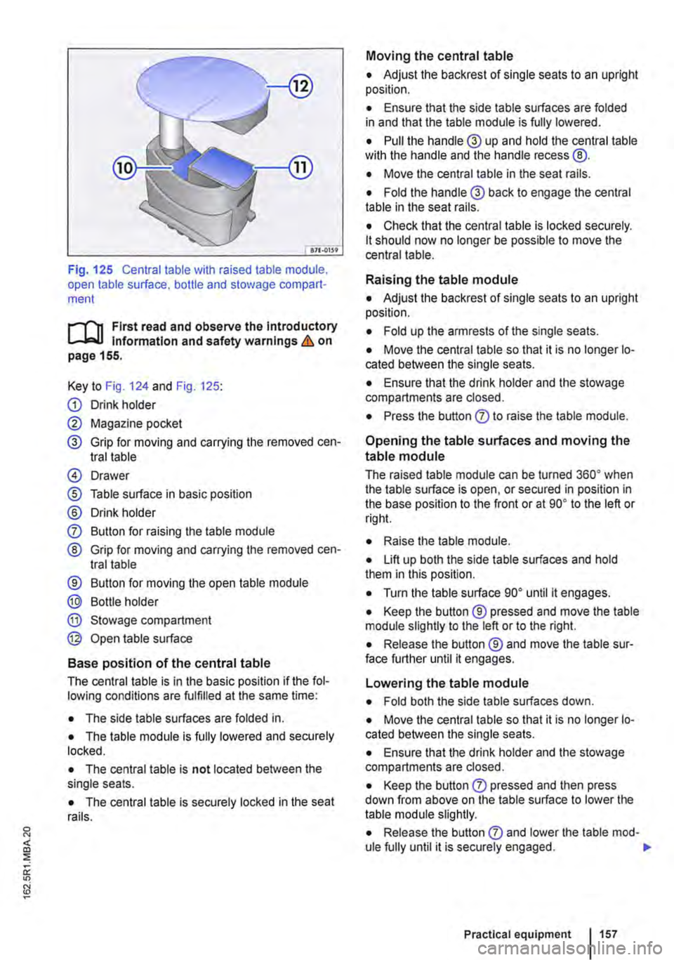
Fig. 125 Central table with raised table module, open table surface. bottle and stowage compart-ment
r-1'11 First read and observe the Introductory l.-Jr:-lJ Information and safety warnings & on page 155.
Key to Fig. 124 and Fig. 125:
G) Drink holder
0 Magazine pocket
® Grip for moving and carrying the removed cen-tral table
@ Drawer
® Table surface in basic position
® Drink holder
0 Button for raising the table module
® Grip for moving and carrying the removed cen-tral table
® Button for moving the open table module
® Bottle holder
® Stowage compartment
@ Open table surface
Base position of the central table
The central table is in the basic position if the fol-lowing conditions are fulfilled at the same time:
• The side table surfaces are folded in.
• The table module is fully lowered and securely locked.
• The central table is not located between the single seats.
• The central table is securely locked in the seat rails.
Moving the central table
• Adjust the backrest of single seats to an upright position.
• Ensure that the side table surfaces are folded in and that the table module is fully lowered.
• Pull the handle® up and hold the central table wilh the handle and the handle recess @.
• Move the central table in the seat rails.
• Fold the handle® back to engage the central table in the seat rails.
• Check that the central table is locked securely. lt should now no longer be possible to move the central table.
Raising the table module
• Adjust the backrest of single seats to an upright position.
• Fold up the armrests of the single seats.
• Move the central table so that it is no longer lo-cated between the single seats.
• Ensure that the drink holder and the stowage compartments are closed.
• Press the button 0 to raise the table module.
Opening the table surfaces and moving the
table module
The raised table module can be turned 36o• when the table surface is open, or secured in position in the base position to the front or at go• to the left or rig hi.
• Raise lhe table module.
• Lift up both the side table surfaces and hold them in this position.
• Turn the table surface go• until it engages.
• Keep the button ® pressed and move the table module slightly to the left or to the right.
• Release the button ® and move the table sur-face further until it engages.
Lowering the table module
• Fold both the side table surfaces down.
• Move the central table so that it is no longer lo-cated between the single seats.
• Ensure that the drink holder and the stowage compartments are closed.
• Keep the button 0 pressed and then press down from above on the table surface to lower the table module slightly.
• Release the button 0 and lower lhe table mod-ule fully until it is securely engaged. .,.
Practical equipment 1157