bench seat VOLKSWAGEN TRANSPORTER 2018 Owners Manual
[x] Cancel search | Manufacturer: VOLKSWAGEN, Model Year: 2018, Model line: TRANSPORTER, Model: VOLKSWAGEN TRANSPORTER 2018Pages: 486, PDF Size: 69.28 MB
Page 64 of 486

Overview of seats
Fig. 41 Overview of seats: short wheelbase (top), long wheelbase (bottom).
ro First read and observe the Introductory Information and safety warnings & on page 61.
Overview of seats 1)
Fig. 41 Short wheelbase Long wheelbase (7 seats max.) (8 seats max.)
1st seat row CD 2 single seats facing in direction of travel
2nd seat row® 1 or 2 single seats facing in direction of travel or in opposite direction of travel
3rd seat row 0 3-seat bench OR 2 single seats 1 or 2 single seats facing in direc-facing in direction of travel lion of travel
4th seat row @
Number of seats
The vehicle has a total of 8 seats: 2 at the front and up to 6 at the rear. Each seat is equipped with a seat belt.
Retrofitting seats
Additional seats can be retrofitted, provided that the maximum number of seats quoted by the man-ufacturer is not exceeded. For this purpose, seat
1> Use of seats 1n accordance with type approval.
Before the journey
-3-seat bench OR 2 single seats facing in direction of travel
anchor points should be fitted to the vehicle floor by a specialist workshop in accordance with Volks-wagen AG guidelines.
These additional seats must also have seat belt anchor points and suitable seat belts.
The Volkswagen Commercial Vehicles dealership can provide you with more information on retrofit-ting seats. .,.
Page 72 of 486

Seat functions, rear
Cl:lJ Introduction
This chapter contains information on the following subjects:
Single seats .
3-seat bench
Drawers in the 3-seat bench ......•.....
Bed extension (multi-flex board) ... Centre armrest ......................... .
Additional information and warnings:
• Adjusting the seat position 61
• Seat belts ""page 79
• Airbag system 87
• Child seats (accessories) :;.page 96
• Luggage compartment :;. page 130
• Guide rail system in rear vehicle floor :;.page 133
• Stowage ""page 150
• Vehicle tool kit ""page 416
A WARNING
73
74
76
77 78
Incorrect use of the seat functions can cause serious injuries.
• Always assume a correct sitting position before you drive and maintain this position throughout the trip. This also applies to all passengers.
721 Before the journey
A WARNING (Continued)
• Keep hands, fingers, feet and other body parts away from the moving parts of the seats.
A WARNING
Incorrect adjustment or removing and fitting single seats and/or the bench seats can cause accidents and severe Injuries.
• All adjustments as well as removing/fitting should be carried out only when the vehicle is stationary; otherwise the single seats and/ or the bench seats could move suddenly when the vehicle Is In motion. Furthermore, an Incorrect seating position Is adopted while adjusting the seat.
• All single seats and the bench seats must always be fitted In their retainers and must be securely engaged.
• Never use the table while the vehicle is In motion. All backrests must be In the upright position and securely engaged in this posi-tion while the vehicle Is In motion.
• Never fit single seats behind the 3-seat bench.
• Never fit two 3-seat benches In the vehi-cle.
• While fitting and removing the single seats and/or the bench seat, make sure that the seat feet are not soiled or damaged.
• Never use child seats In the groups 0 or 0+ on single seats that face the rear of the vehicle. <
Page 74 of 486
Turning the single seat
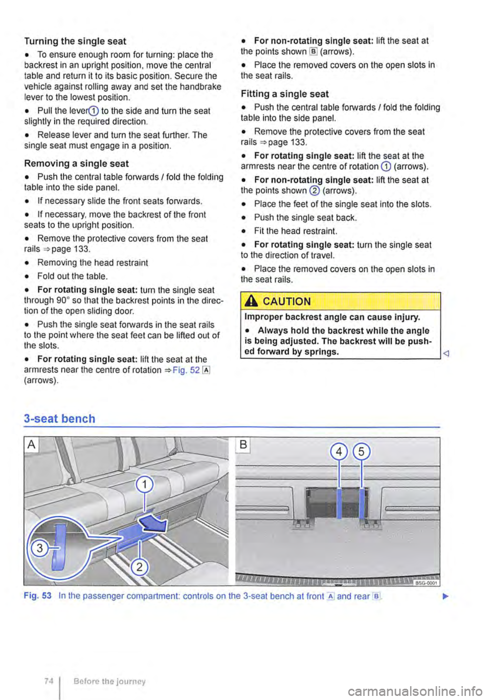
• To ensure enough room for turning: place the backrest in an upright position. move the central table and return it to its basic position. Secure the vehicle against rolling away and set the handbrake lever to the lowest position.
• Pull the lever(D to the side and turn the seat slightly in the required direction.
• Release lever and turn the seat further. The single seat must engage in a position.
Removing a single seat
• Push the central table forwards I fold the folding table into the side panel.
• If necessary slide the front seats forwards.
• If necessary, move the backrest of the front seats to the upright position.
• Remove the protective covers from the seat rails 133.
• Removing the head restraint
• Fold out the table.
• For rotating single seat: turn the single seat through go• so that the backrest points in the direc-tion of the open sliding door.
• Push the single seat forwards in the seat rails to the point where the seat feet can be lifted out of the slots.
• For rotating single seat: lift the seat at the armrests near the centre of rotation (arrows).
3-seat bench
• For non-rotating single seat: lift the seat at the points shown [ID (arrows).
• Place the removed covers on the open slots in the seat rails.
Fitting a single seat
• Push the central table forwards I fold the folding table into the side panel.
• Remove the protective covers from the seat rails 133.
• For rotating single seat: lift the seat at the armrests near the centre of rotation G) (arrows).
• For non-rotating single seat: lift the seat at the points shown@ (arrows).
• Place the feet of the single seat into the slots.
• Push the single seat back.
• Fit the head restraint.
• For rotating single seat: turn the single seat to the direction of travel.
• Place the removed covers on the open slots in the seat rails.
A CAUTION
Improper backrest angle can cause injury.
• Always hold the backrest while the angle is being adjusted. The backrest will be push-ed forward by springs.
Before the journey
Page 75 of 486
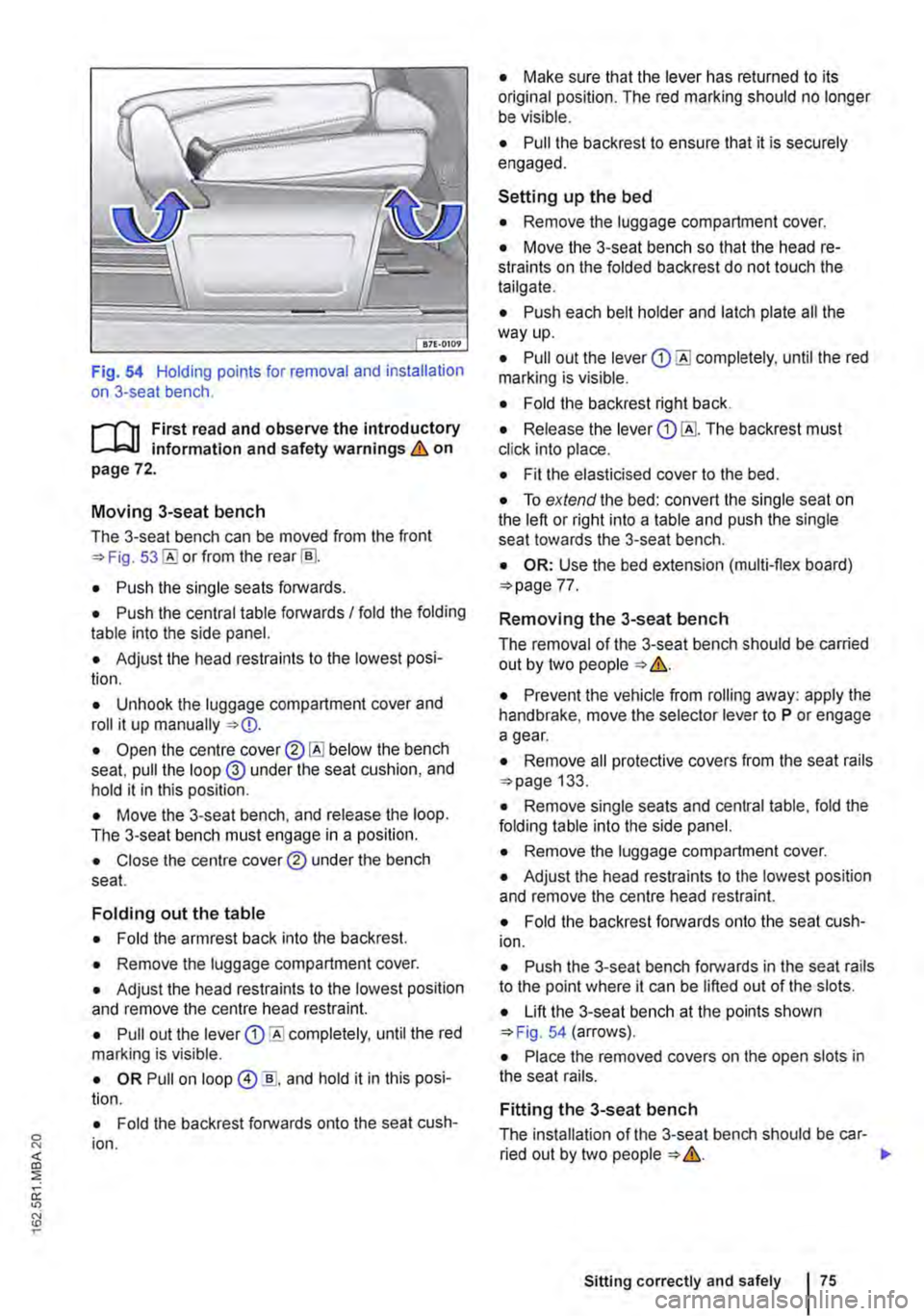
Fig. 54 Holding points for removal and installation on 3-seat bench.
,....-m First read and observe the introductory L-W.I information and safety warnings & on page 72.
Moving 3-seat bench
The 3-seat bench can be moved from the front =>Fig. or from the rear [ru.
• Push the single seats forwards.
• Push the central table forwards I fold the folding table into the side panel.
• Adjust the head restraints to the lowest posi-tion.
• Unhook the luggage compartment cover and roll it up manually =>
• Move the 3-seat bench, and release the loop. The 3-seat bench must engage in a position.
• Close the centre cover® under the bench seat.
Folding out the table
• Fold the armrest back into the backrest.
• Remove the luggage compartment cover.
• Adjust the head restraints to the lowest position and remove the centre head restraint.
• Pull out the lever Q) completely, until the red marking is visible.
• OR Pull on loop @ ]], and hold it in this posi· lion.
• Fold the backrest forwards onto the seat cush· ion.
• Make sure that the lever has returned to its original position. The red marking should no longer be visible.
• Pull the backrest to ensure that it is securely engaged.
Setting up the bed
• Remove the luggage compartment cover.
• Move the 3-seat bench so that the head re· straints on the folded backrest do not touch the tailgate.
• Push each belt holder and latch plate all the way up.
• Pull out the lever Q) until the red marking is visible.
• Fold the backrest right back.
• Release the lever Q) The backrest must click into place.
• Fit the elasticised cover to the bed.
• To extend the bed: convert the single seat on the left or right into a table and push the single seat towards the 3-seat bench.
• OR: Use the bed extension (multi-flex board) =>page 77.
Removing the 3-seat bench
The removal of the 3-seat bench should be carried out by two people => &.
• Prevent the vehicle from rolling away: apply the handbrake, move the selector lever to P or engage a gear.
• Remove all protective covers from the seat rails =>page 133.
• Remove single seats and central table, fold the folding table into the side panel.
• Remove the luggage compartment cover.
• Adjust the head restraints to the lowest position and remove the centre head restraint.
• Fold the backrest forwards onto the seat cush-ion.
• Push the 3-seat bench forwards in the seat rails to the point where it can be lifted out of the slots.
• Lift the 3-seat bench at the points shown =>Fig. 54 (arrows).
• Place the removed covers on the open slots in the seat rails.
Fitting the 3-seat bench
The installation of the 3-seat bench should be car-ried out by two people => &. .,.
Sitting correctly and safely
Page 76 of 486

• Remove all protective covers from the seat rails =-page 133.
• Lift the 3-seat bench at the points shown =>Fig. 54 (arrows).
• Place the feet of the 3-seat bench into the slots so that the backrest is facing the rear of the vehi-cle.
• Adjust the backrest to an upright position.
• Make sure that the lever or the loop has re-turned to its original position. The red marking should no longer be visible.
• Pull the backrest to ensure that it is securely engaged.
• Insert the single seats and the central table into the seat rails and push them back.
• Lock the single seats and the central table se-curely in the seat rails.
• Place the removed covers on the open slots in the seat rails.
Drawers in the 3-seat bench
r' ,f} I
---
VII f/l/ \\\
Fig. 55 In the 3-seat bench: drawers.
1""111 First read and observe the Introductory L-lo:oJJ information and safety warnings & on page 72.
There are three drawers =-Fig. 55 in the 3-seat bench (Multivan), which can be accessed from the front and from the rear.
All drawers can be removed fully. Drawers can be stacked and stored in a stowage compartment.
Opening and closing the drawer from the front
• To open, press and hold the handle in the han-dle recess and pull up the cover in the same way you would for a "garage door". You can now ac-cess the drawer.
• To close, push the drawer in and press the cov-er down.
76 Before the journey
• Fit the luggage compartment cover.
• Fit the centre head restraint.
A wARNING
The 3-seat bench weighs approximately 90 kg and could cause serious Injuries due to its weight.
• Before removing and fitting it, please con-sider whether you can actually lift it.
CD
If you move or remove the 3-seat bench with the luggage compartment cover, the luggage compartment cover and Its holders could be damaged
m Additional force may have to be applied to W move the 3-seat bench if it has not been moved for a long lime.
• To open, hold the handle in the handle recess and pull the cover back. You can now access the drawer.
• To close, place the cover on the top with the re-taining lugs in the recess and press it down until it engages.
A WARNING
If the drawer Is left open it can hinder the cor-rect operation of the pedals. This can result In accidents and severe Injuries.
• Always keep the drawer closed while the vehicle is in motion. Otherwise the drawer or other items could fall Into the driver footwell and obstruct the pedals.
Page 77 of 486

Bed extension (multi-flex board)
Fig. 56 In the luggage compartment: multi-flex board.
.--m First read and observe the Introductory L-.J,..U lnfonmatlon and safety warnings & on page 72.
Key to Fig. 56 and Fig. 57:
CD Rear surface (can be folded up)
@ Front surface (can be folded down)
@ Lever for folding the front surface down
@ Handles (one each for left and right)
® Thumb wheel (one each for left and right)
The multi-flex board can be used to extend the bed surface of the 3-seat bench.
The multi-flex board consists of two folding surfa-ces. The front surface =>Fig. 56@ can be folded down using lever@. The rear surface CD can be folded up. When doing so, always hang the loop over a head restraint to prevent the surface falling down.
The multi-flex board can be fitted and removed more easily by two people than by one person.
Fitting the multi-flex board
• Move the 3-seat bench forward so that the mul-ti-flex board can be fitted.
• Insert the multi-flex board into the outside seat rails. Make sure that the handles =>Fig. 57@ are at right-angles to the seat rails and that the T-sha-ped holding screws are parallel to the seat rails.
• Press both the handles@ down and turn them through go• so that they are parallel to the seat rails.
Fig. 57 In the luggage compartment: multi-flex board in right seat rail with handle @ and thumb wheel@
• Tighten both the thumb wheels® firmly.
• Make sure that the multi-flex board is locked securely in the seat rails and that both thumb wheels have been tightened firmly.
Moving the multi-flex board
• Loosen both the thumb wheels @.
• Move the multi-flex board to the desired posi-tion.
• Tighten both the thumb wheels® firmly.
Removing the multi-flex board
• Loosen both the thumb wheels® completely.
• Turn both the handles@ in the direction of the arrow through 90 degrees.
• Make sure that front surface =>Fig. 56@ and rear surface CD are folded down and engaged se-curely.
• Remove the multi-flex board.
• Make sure that the T-shaped holders are not soiled or damaged.
Setting up the bed
• Push the multi-flex board backwards to the stop.
• Push the single seats forwards as far as they will go and turn them to face the rear of the vehi-cle.
• Stow the folding table or the central table.
• Remove the head restraints on the 3-seat bench.
• Pull the lever =>Fig. 53 CD out fully, until the red marking is visible. 11>
Sitting correctly and safely
Page 78 of 486

• Fold the backrest of the 3-seat bench com-pletely forwards onto the seat cushion.
• Open the centre cover 53®@ below the bench seat, pull the loop @ under the seat cushion, and hold it in this position.
• Push the 3-seat bench forward to the single seats, and release the loop. The 3-seat bench must contact the seat cushions of the single seats.
• Pull the lever 53 CD out fully, until the red marking is visible.
• Fold the backrest of the 3-seat bench com-pletely backwards.
• Make sure that the lever has returned to its original position. The red marking should no longer be visible.
• Fold up the front surface 56® of the multi-flex board.
• Place the supplied mattress on the multi-flex board.
• Fit the elasticised cover to the bed.
A WARNING
Objects that are not secured, or are secured incorrectly, can cause serious injuries in the event of a sudden driving or braking manoeu-vre or accident.
Centre armrest
Fig. 58 Centre armrest on the 3-seat bench
1"'1'11 First read and observe the introductory l.-J,::.IJ information and safety warnings & on page 72.
78 Before the journey
A WARNING (Continued)
• Never place any objects on the multi-flex board while the vehicle Is In motion.
• The multi-flex board must always be fitted in the seat rails and must be securely engag-ed when the vehicle Is In motion.
A WARNING
Improper use of the multi-flex board can cause serious Injury.
• The rear surface CD must always be folded down when the vehicle Is In motion.
• Never fit the multi-flex board In front of the 3-seat bench.
Q)
This could damage the cool box If the bed ex-tension Is fitted (multi-flex board).
• The front surface® of the bed extension (multi-flex board) should always be folded up and engaged securely.
m If the multi-flex board is fitted in the rear posi-L!..J lion. the fastening rings cannot be used.
• To fold the centre armrest down, pull the loop 58 up until it engages.
• To fold the centre armrest back, press against the middle of the end face of the centre armrest when folded down and move it up fully. The sur-rounding upholstery must be flush with the centre armrest.
A WARNING
Transporting a person or a child on the cen-tre armrest can lead to accidents and severe or fatal Injury.
• Never transport an adult or child on the
__
Page 91 of 486
The airbag system is part of the vehicle's overall passive safety concept. The airbag system can on-ly work effectively when the occupants are wearing their seat belts correctly and have assumed a proper sitting position & 61.
Components of the vehicle safety concept
The following vehicle safety equipment makes up the vehicle's safety concept to reduce the risk of severe and fatal injuries. Some of this equipment may not be fitted in your particular vehicle. lt may not be available at all in some countries.
• Optimised seat belts for all seats.
• Belt tensioners for the driver and front passen-ger in conjunction with curtain and side airbags.
• Belt height adjuster for the front seats.
• Seat belt warning lamp.
• Front airbags for driver and front passenger.
• Combined curtain and side airbags for the driv-er and front passenger.
• Multivan: if fitted, curtain airbags on the rear outer seats of the second and third row of seats.
• Airbag indicator lamp.
• PASSENGER AIR BAG indicator lamp.
• Control units and sensors.
• Height-adjustable head restraints optimised for rear Impact.
• Adjustable steering column.
• If fitted, anchor points for child seats on the sin-gle seats in the passenger compartment and the outer seats of the bench seat.
Situations in which the front, the combined curtain and side airbag and the curtain airbag will not be triggered:
• If the ignition is switched off during a collision.
• If the level of deceleration measured by the control unit is too low during a collision at the front of the vehicle.
• During a minor side collision.
• During rear collisions.
• If the vehicle rolls over.
• If the impact speed in a collision is lower than the reference value specified in the control unit. <1
Sitting correctly and safely I 91
Page 100 of 486
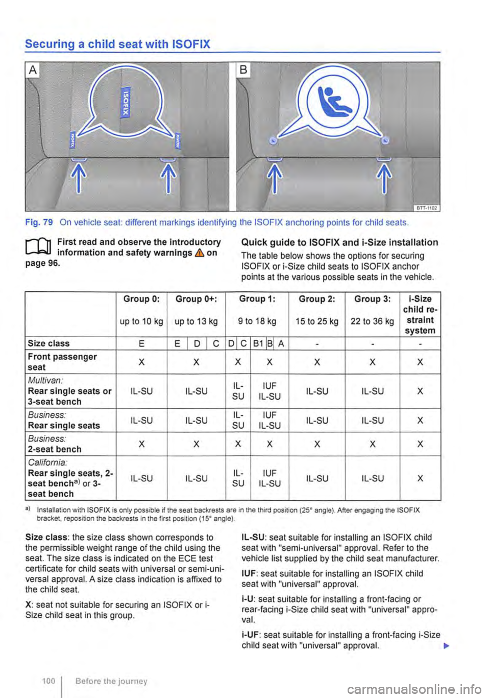
Fig. 79 On vehicle seat: different markings identifying the ISOFIX anchoring points for child seats.
1"'1'11 First read and observe the Introductory l..-J,::,IJ information and safety warnings & on page 96.
Group 0: Group 0+:
upto10kg up to 13 kg
Size class E EIDIC
Front passenger X X seat
Multivan: Rear single seats or IL-SU IL-SU 3-seat bench
Business: IL-SU IL-SU Rear single seats
Business: X X 2-seat bench
California: Rear single seats, 2-IL-SU IL-SU seat bencha> or 3-seat bench
Quick guide to ISO FIX and i-Size installation
The table below shows the options for securing ISO FIX or i-Size child seats to ISOFIX anchor points at the various possible seats in the vehicle.
Group 1: Group 2: Group 3: 1-Size child re-
9 to 18 kg 15 to 25 kg 22 to 36 kg strain! system
ojc B1jBI A ---
X X X X X
IL-IUF su IL-SU IL-SU IL-SU X
IL-IUF IL-SU IL-SU X su IL-SU
X X X X X
IL-IUF IL-SU IL-SU X su IL-SU
•> Installation with ISOFIX is only possible if the seat backrests are in the third position (25' angle). After engaging the ISOFIX bracket, reposition the backrests in the first position (15' angle).
Size class: the size class shown corresponds to the permissible weight range of the child using the seat. The size class is indicated on the ECE test certificate for child seats with universal or semi-uni-versal approval. A size class indication is affixed to the child seat.
X: seat not suitable for securing an ISOFIX or i-Size child seat in this group.
100 I Before the journey
IL-SU: seat suitable for installing an ISOFIX child seat with "semi-universal" approval. Refer to the vehicle list supplied by the child seat manufacturer.
IUF: seat suitable for installing an ISOFIX child seat with "universal" approval.
i-U: seat suitable for installing a front-facing or rear-facing i-Size child seat with "universal" appro-val.
i-UF: seat suitable for installing a front-facing i-Size child seat with "universal" approval.
Page 101 of 486
Installing child seats with ISOFIX ISOFIX/i-
Size
The location of the ISO FIX anchor points is shown either by a symbol or by a label marked "ISOFIX" 79.
• Observe the warnings 97, Basic infor-mation on fitting and using child seats.
• Push the attachment arms on the child seat into the ISOFIX anchor points 79 as shown by the arrows. The child seat must click and audibly securely into place.
• Pull on both sides of the child seat to check whether the seat has clicked properly into place.
• If the child seat is fitted with a support foot, the foot must sit firmly on the floor of the vehicle.
Using insert guides
If the child seat anchor points are not directly ac-cessible, insert guides make fitting and removing the child seat easier. First attach the insert guides to the anchor points. Then secure the child seat as per the installation guide.
CD
Avoid damage to the upholstery and seat cush-ions caused by the Insert guides.
• Always pull the insert guides off the anchor points before folding the rear seat forward, or when removing the child seat.
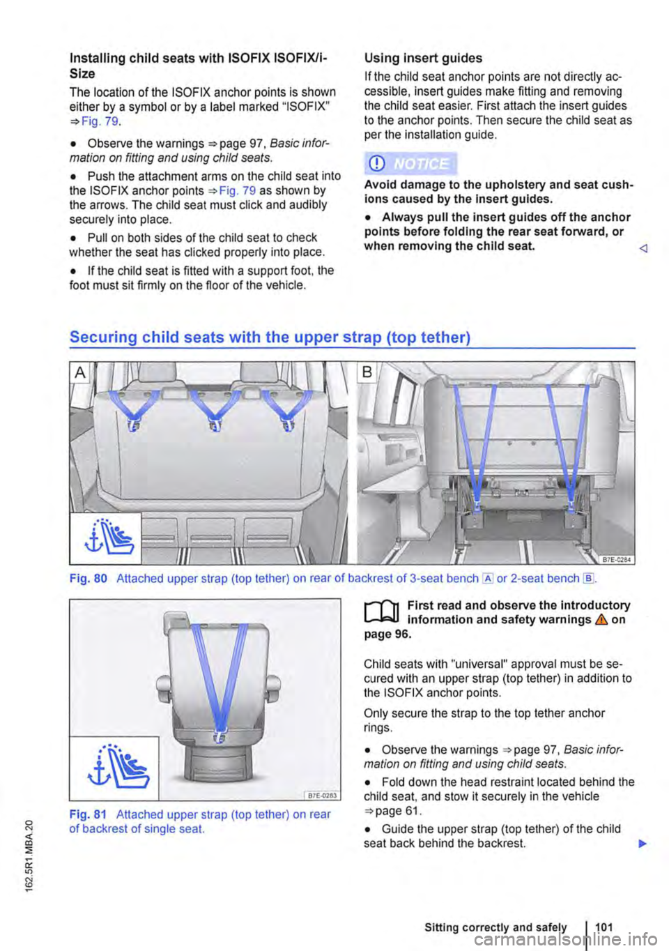
Fig. 80 Attached upper strap (top tether) on rear of backrest of 3-seat or 2-seat bench [ID.
87E-0783
Fig. 81 Attached upper strap (top tether) on rear of backrest of single seat.
r-1'11 First read and observe the Introductory L-lcJ.I Information and safety warnings & on page 96.
Child seats with "universal" approval must be se-cured with an upper strap (top tether) in addition to the ISOFIX anchor points.
Only secure the strap to the top tether anchor rings.
• Observe the warnings 97, Basic infor-mation on fitting and using child seats.
• Fold down the head restraint located behind the child seat, and stow it securely in the vehicle 61.
• Guide the upper strap (top tether) of the child seat back behind the backrest. )I>
Sitting correctly and safely 1101