remote control VOLKSWAGEN TRANSPORTER 2020 Owner's Manual
[x] Cancel search | Manufacturer: VOLKSWAGEN, Model Year: 2020, Model line: TRANSPORTER, Model: VOLKSWAGEN TRANSPORTER 2020Pages: 486, PDF Size: 69.28 MB
Page 335 of 486
Remote control
B
BSG·OOS3
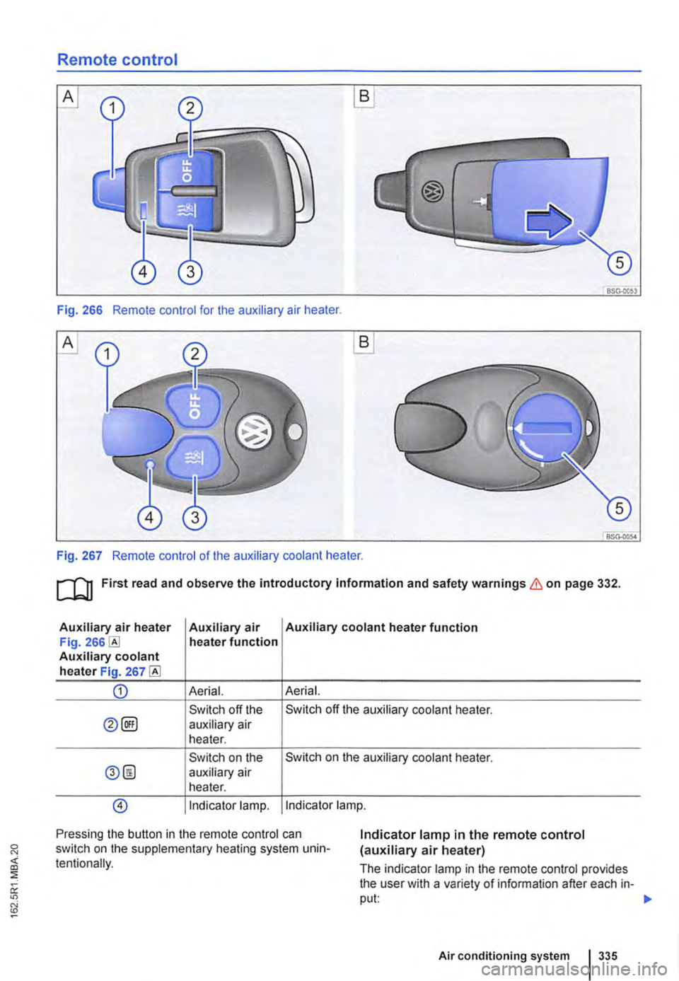
Fig. 266 Remote control for the auxiliary air heater.
A
BSG-0054
Fig. 267 Remote control of the auxiliary coolant heater.
ru First read and observe the introductory Information and safety warnings & on page 332.
Auxiliary air heater Auxiliary air Auxiliary coolant heater function Fig. heater function Auxiliary coolant heater Fig. 267
CD Aerial. Aerial.
Switch off the Switch off the auxiliary coolant heater.
0@) auxiliary air heater.
Switch on the Switch on the auxiliary coolant heater.
0@ auxiliary air heater.
@) Indicator lamp. Indicator lamp.
Pressing the button in the remote control can switch on the supplementary heating system unin-tentionally.
Indicator lamp in the remote control (auxiliary air heater)
The indicator lamp in the remote control provides the user with a variety of information after each in-put: 1>-
Air conditioning system 335
Page 336 of 486
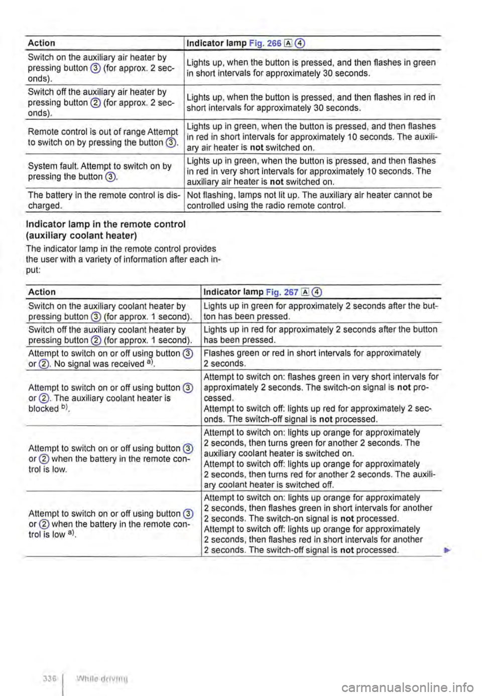
Action I Indicator lamp Fig. 266
Switch on the auxiliary air heater by pressing button @ (for approx. 2 sec-onds).
Switch off the auxiliary air heater by pressing button ® (for approx. 2 sec-onds).
Lights up, when the button is pressed, and then flashes in green in short intervals for approximately 30 seconds.
Lights up, when the button is pressed, and then flashes in red in short intervals for approximately 30 seconds.
Lights up in green, when the button is pressed, and then flashes Remote control is out of range Attempt in red in short intervals for approximately 10 seconds. The auxili-to switch on by pressing the button @. ary air heater is not switched on.
System fault. Attempt to switch on by pressing the button @.
Lights up in green, when the button is pressed, and then flashes in red in very short intervals for approximately 10 seconds. The auxiliary air heater is not switched on.
The battery in the remote control is dis-charged. Not flashing, lamps not lit up. The auxiliary air heater cannot be controlled using the radio remote control.
Indicator lamp in the remote control (auxiliary coolant heater)
The indicator lamp in the remote control provides the user with a variety of information after each in-put:
Action Indicator lamp Fig. 267
Switch on the auxiliary coolant heater by Lights up in green for approximately 2 seconds after the but-pressing button@ (for approx. 1 second). ton has been pressed.
Switch off the auxiliary coolant heater by Lights up in red for approximately 2 seconds after the button pressing button® (for approx. 1 second). has been pressed.
Attempt to switch on or off using button @ Flashes green or red in short intervals for approximately or@. No signal was received a). 2 seconds.
Attempt to switch on: flashes green in very short intervals for Attempt to switch on or off using button@ approximately 2 seconds. The switch-on signal is not pro-or@. The auxiliary coolant heater is cessed. blocked b). Attempt to switch off: lights up red for approximately 2 sec-onds. The switch-off signal is not processed.
Attempt to switch on: lights up orange for approximately
Attempt to switch on or off using button@ 2 seconds, then turns green for another 2 seconds. The
or® when the battery in the remote con-auxiliary coolant heater is switched on. Attempt to switch off: lights up orange for approximately trot is low. 2 seconds, then turns red for another 2 seconds. The auxili-ary coolant heater is switched off.
Attempt to switch on: lights up orange for approximately
Attempt to switch on or off using button @ 2 seconds, then flashes green in short intervals for another
or® when the battery in the remote con-2 seconds. The switch-on signal is not processed.
trot is low a). Attempt to switch off: lights up orange for approximately 2 seconds, then flashes red in short intervals for another 2 seconds. The switch-off signal is not processed.
336 I While droving
Page 337 of 486
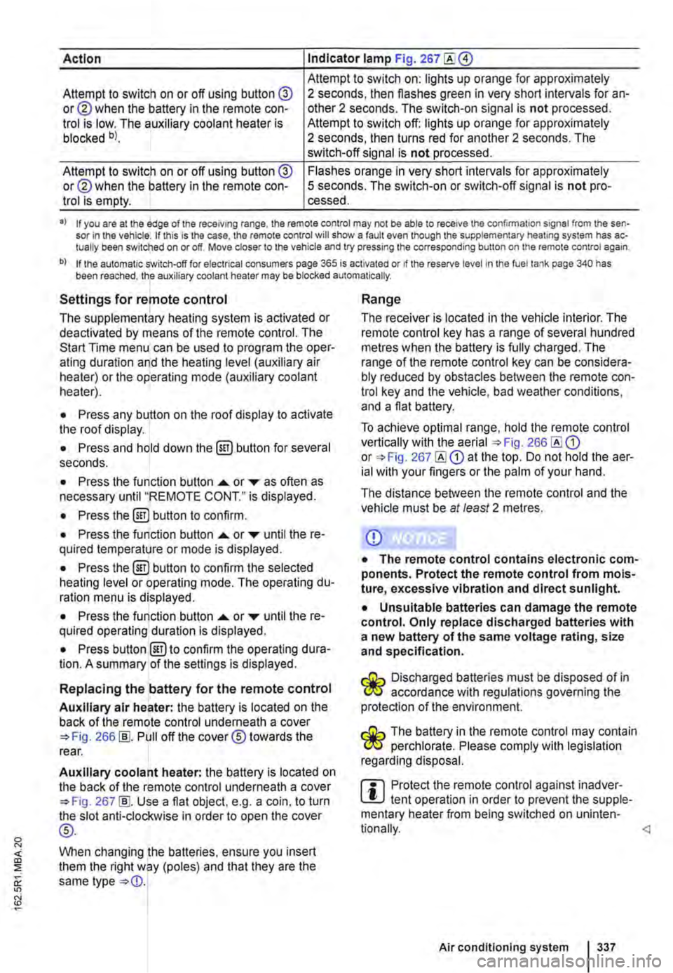
Action Indicator lamp Fig. 267
Attempt to switch on: lights up orange for approximately Attempt to switch on or off using button @ or@ when the battery in the remote con-trol is low. The auxiliary coolant heater is blocked bl.
2 seconds, then flashes green in very short intervals for an-other 2 seconds. The switch-on signal is not processed. Attempt to switch off: lights up orange for approximately 2 seconds, then turns red for another 2 seconds. The switch-off signal is not processed.
Attempt to switch on or off using button @ or@ when the battery in the remote con-trol is empty.
Flashes orange in very short intervals for approximately 5 seconds. The switch-on or switch-off signal is not pro-cessed.
•> If you are at the edge of the receiving range, the remote control may not be able to receive the confirmation signal from the sen-sor in the vehicle. If this is the case, the remote control will show a fault even though the supplementary heating system has ac-tually been switched on or off. Move closer to the vehicle and try pressing the corresponding button on the remote control again.
b) If the automatic switch-off for electrical consumers page 365 is activated or if the reserve level in lhe fuel tank page 340 has been reached, the auxiliary coolant heater may be blocked automatically.
Settings for remote control
The supplementary heating system is activated or deactivated by means of the remote control. The Start Time menu can be used to program the oper-ating duration and the heating level (auxiliary air heater) or the operating mode (auxiliary coolant heater).
• Press any button on the roof display to activate the roof display.
• Press and hold down the (ill) button for several seconds.
• Press the function button ...... or ,... as often as necessary until "REMOTE CONT." is displayed.
• Press the (ill) button to confirm.
• Press the function button ...... or ,... until the re-quired temperature or mode is displayed.
• Press the (ill) button to confirm the selected heating level or operating mode. The operating du-ration menu is displayed.
• Press the function button ...... or ,... until the re-quired operating duration is displayed.
• Press button @)to confirm the operating dura-tion. A summary of the settings is displayed.
Replacing the battery for the remote control
Auxiliary air heater: the battery is located on the back of the remote control underneath a cover 266 [ID. Pull off the cover® towards the rear.
Auxiliary coolant heater: the battery is located on the back of the remote control underneath a cover 267 [ID. Use a flat object, e.g. a coin, to turn the slot anti-clockwise in order to open the cover
®-
When changing the batteries, ensure you insert them the right way (poles) and that they are the same type
Range
The receiver is located in the vehicle interior. The remote control key has a range of several hundred metres when the battery is fully charged. The range of the remote control key can be considera-bly reduced by obstacles between the remote con-trol key and the vehicle, bad weather conditions, and a flat battery.
To achieve optimal range, hold the remote control vertically with the aerial 266 or 267 at the top. Do not hold the aer-ial with your fingers or the palm of your hand.
The distance between the remote control and the vehicle must be at least 2 metres.
CD
• The remote control contains electronic com-ponents. Protect the remote control from mois-ture, excessive vibration and direct sunlight.
• Unsuitable batteries can damage the remote control. Only replace discharged batteries with a new battery of the same voltage rating, size and specification.
Discharged batteries must be disposed of in W accordance with regulations governing the protection of the environment.
The battery in the remote control may contain W perchlorate. Please comply with legislation regarding disposal.
m Protect the remote control against inadver-L!.J tent operation in order to prevent the supple-mentary heater from being switched on uninten-
Air conditioning system I 337
Page 406 of 486
CD
• Volkswagen Commercial Vehicles Is not re-sponsible for any vehicle damage which Is caused by low-quality fuel, inadequate servic-ing work or lack of availability of Genuine Parts.
Radio reception and aerials
i"""(")1 First read and observe the Introductory l-J.::.U information and safety warnings & on page 404.
The vehicle aerials are located in the exterior mir-rors. If any metallic chrome plates, such as chrome mirror caps, are retrofitted to the exterior mirrors you may experience problems with the radio,
CD
• Volkswagen Commercial Vehicles cannot be held responsible If the vehicle does not comply with or only partly complies with the relevant legal requirements In other countries and conti-nents.
m Interference with AM radio reception could W occur if electrical devices are used in the vi-cinity of the aerial.
i"""(")1 and observe the introductory l-J.::.U mformat1on and safety warnings & on page 404.
Volkswagen Commercial Vehicles Service infonna-tion and official Volkswagen Commercial Vehicles repair infonnation can be purchased from the fol-lowing addresses:
Please contact a Volkswagen Commercial Vehicles dealership or a qualified workshop or order the lit-erature you require from www.erwin.volkswagen.de.
Declaration of conformity
i"""(")1 First read and observe the introductory l-J.::.U information and safety warnings & on page 404.
The individual manufacturer declares herewith that the following products conform, at the time of vehi-cle production, with the basic requirements and other relevant laws and regulations, including FCC Part 15.19, FCC Part 15.21 and RSS-Gen Issue 1:
4061 Clean1ng and mamtenance
A WARNING
Incorrect repairs and modifications can cause functional problems and damage to the vehicle and impair the effectiveness of the driver assist systems and the alrbag sys-tems. This can result In accidents and severe Injuries.
• Repairs and modifications to your vehicle should only be carried out by a qualified workshop.
• Electronic immobilizer.
• Remote control key for the vehicle.
• Remote control for the supplementary heating system (auxiliary heater).
Electrical equipment
• 12-volt socket.
Page 410 of 486
If and when
Practical tips
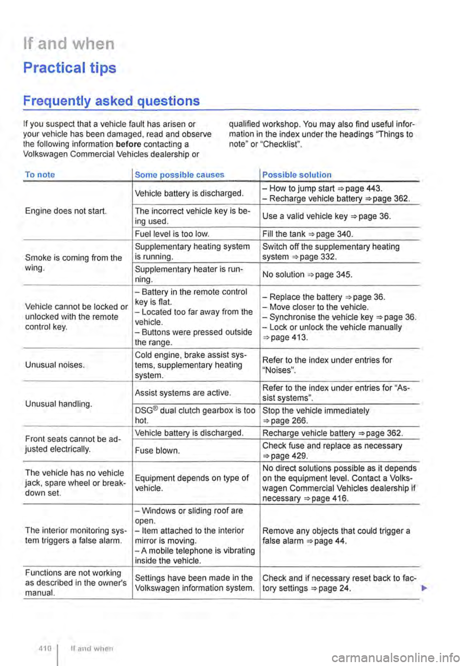
Frequently asked questions
If you suspect that a vehicle fault has arisen or your vehicle has been damaged, read and observe the following information before contacting a Volkswagen Commercial Vehicles dealership or
qualified workshop. You may also find useful infor-mation in the index under the headings "Things to note" or "Checklist".
To note Some possible causes Possible solution
Vehicle battery is discharged. -How to jump start =>page 443. -Recharge vehicle battery 362.
Engine does not start. The incorrect vehicle key is be-Use a valid vehicle key 36. ing used.
Fuel level is too low. Fill the tank 340.
Supplementary heating system Switch off the supplementary heating
Smoke is coming from the is running. system 332. wing. Supplementary heater is run-No solution 345. ning.
-Battery in the remote control -Replace the battery 36. Vehicle cannot be locked or key is flat. -Move closer to the vehicle. unlocked with the remote -Located too far away from the -Synchronise the vehicle key =>page 36. vehicle. control key. -Buttons were pressed outside -Lock or unlock the vehicle manually
the range. 413.
Cold engine. brake assist sys-Refer to the index under entries for Unusual noises. tems, supplementary heating "Noises". system.
Assist systems are active. Refer to the index under entries for "As-sist systems". Unusual handling. DSG® dual clutch gearbox is too Stop the vehicle immediately hot. 266.
Front seats cannot be ad-Vehicle battery is discharged. Recharge vehicle battery 362.
justed electrically. Fuse blown. Check fuse and replace as necessary 429.
The vehicle has no vehicle No direct solutions possible as it depends
jack, spare wheel or break-Equipment depends on type of on the equipment level. Contact a Volks-vehicle. wagen Commercial Vehicles dealership if down set. necessary 416.
-Windows or sliding roof are open. The interior monitoring sys--Item attached to the interior Remove any objects that could trigger a tem triggers a false alarm. mirror is moving. false alarm 44. -A mobile telephone is vibrating inside the vehicle.
Functions are not working Settings have been made in the Check and if necessary reset back to fac-as described in the owner's manual. Volkswagen information system. tory settings 24.
410 I If and when
Page 413 of 486
First aid kit, warning triangle, high-visibility waistcoat and fire
extinguisher
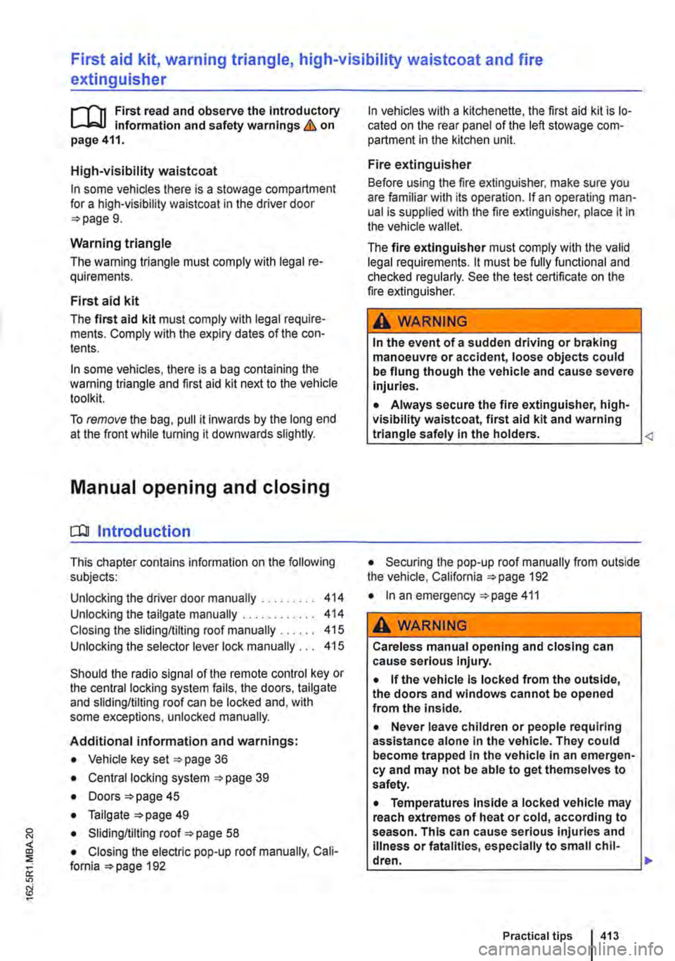
l"'""'('n First read and observe the introductory L.-J,::,JI Information and safety warnings & on page 411.
High-visibility waistcoat
In some vehicles there is a stowage compartment for a high-visibility waistcoat in the driver door 9.
Warning triangle
The warning triangle must comply with legal re-quirements.
First aid kit
The first aid kit must comply with legal require-ments. Comply with the expiry dates of the con-tents.
In some vehicles, there is a bag containing the warning triangle and first aid kit next to the vehicle toolkit.
To remove the bag, pull it inwards by the long end at the front while turning it downwards slightly.
Manual opening and closing
COl Introduction
This chapter contains information on the following subjects:
Unlocking the driver door manually . . . . . . . . . 414 Unlocking the tailgate manually ............ 414
Closing the sliding/tilting roof manually . . . . . 415
Unlocking the selector lever lock manually . . . 415
Should the radio signal of the remote control key or the central locking system fails, the doors, tailgate and sliding/tilting roof can be locked and, with some exceptions, unlocked manually.
Additional information and warnings:
• Vehicle key set 36
• Central locking system 39
• Doors 45
• Tailgate 49
• Sliding/tilting roof 58
• Closing the electric pop-up roof manually, Cali-fornia 192
In vehicles with a kitchenette, the first aid kit is lo-cated on the rear panel of the left stowage com-partment in the kitchen unit.
Fire extinguisher
Before using the fire extinguisher, make sure you are familiar with its operation. If an operating man-ual is supplied with the fire extinguisher, place it in the vehicle wallet.
The fire extinguisher must comply with the valid legal requirements. lt must be fully functional and checked regularly. See the test certificate on the fire extinguisher.
A WARNING
In the event of a sudden driving or braking manoeuvre or accident, loose objects could be flung though the vehicle and cause severe Injuries.
• Always secure the fire extinguisher, high-visibility waistcoat, first aid kit and warning triangle safely In the holders.
• In an emergency 411
A WARNING
Careless manual opening and closing can cause serious Injury.
• If the vehicle Is locked from the outside, the doors and windows cannot be opened from the inside.
• Never leave children or people requiring assistance alone In the vehicle. They could become trapped In the vehicle In an emergen-cy and may not be able to get themselves to safety.
• Temperatures Inside a locked vehicle may reach extremes of heat or cold, according to season. This can cause serious Injuries and Illness or fatalities, especially to small chil-dren. .,.
Practical tips 413
Page 414 of 486
A WARNING
The path of the doors, tailgate and sliding/tilt-ing roof is a dangerous area. Injuries could be sustained here.
Unlocking the driver door manually
rl'11 First read and observe the introductory L-J.:.I.I Information and safety warnings & on page 413.
If unlocked manually, only the driver door is un-locked. Observe information on the anti-theft alarm 39.
Unlocking the tailgate manually
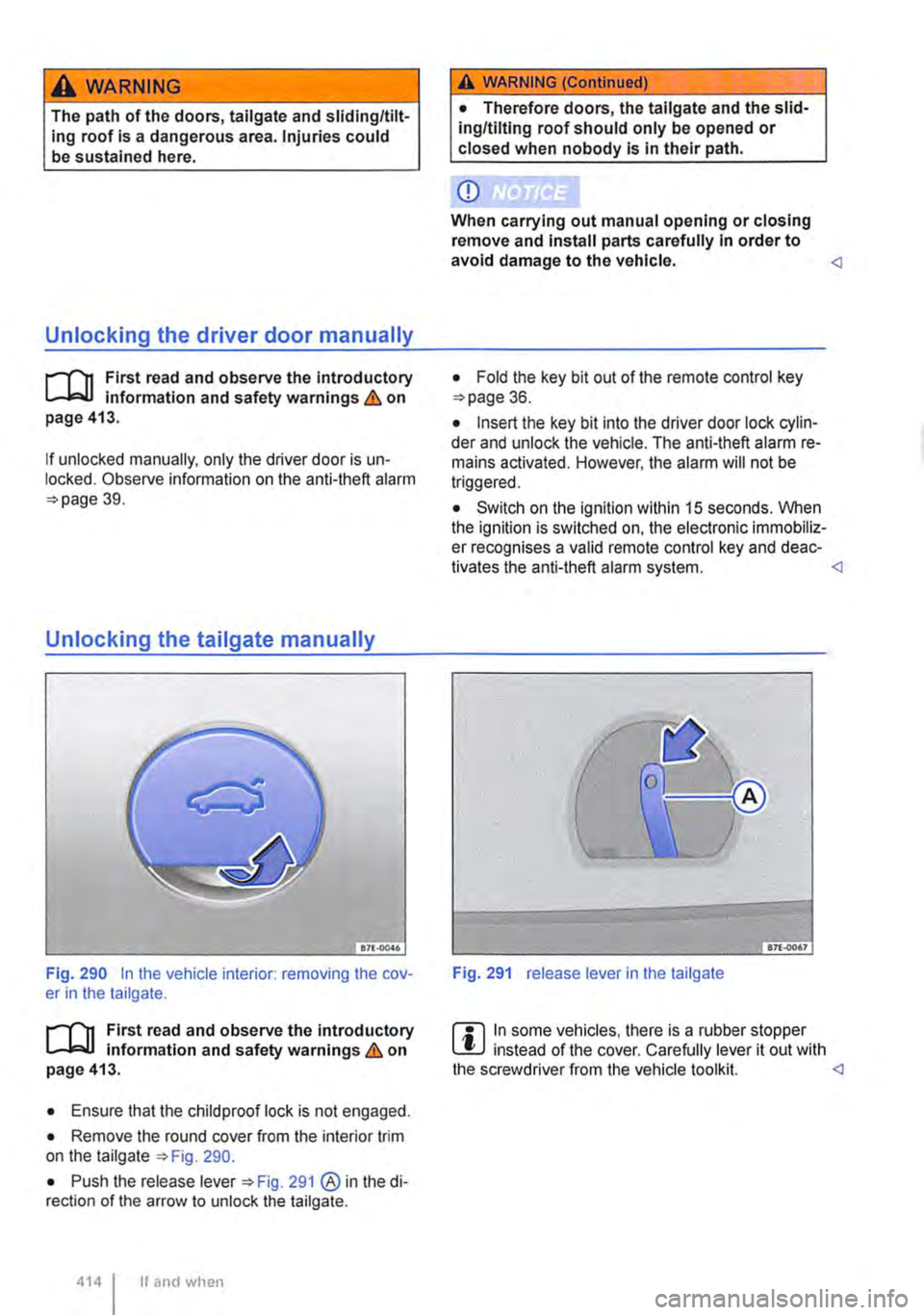
Fig. 290 In the vehicle interior: removing the cov-er in the tailgate.
rl'11 First read and observe the introductory L-J.:.I.I information and safety warnings & on page 413.
• Ensure that the child proof lock is not engaged.
• Remove the round cover from the interior trim on the tailgate 290.
• Push the release lever 291 @ in the di-rection of the arrow to unlock the tailgate.
4141 If and when
A WARNING (Continued)
• Therefore doors, the tailgate and the slid-ing/tilting roof should only be opened or closed when nobody is in their path.
CD
When carrying out manual opening or closing remove and Install parts carefully In order to avoid damage to the vehicle.
• Insert the key bit into the driver door lock cylin-der and unlock the vehicle. The anti-theft alarm re-mains activated. However, the alarm will not be triggered.
• Switch on the ignition within 15 seconds. When the ignition is switched on, the electronic immobiliz-er recognises a valid remote control key and deac-tivates the anti-theft alarm system.
m In some vehicles, there is a rubber stopper l!.J instead of the cover. Carefully lever it out with the screwdriver from the vehicle toolkit.
Page 466 of 486
Vents ............................ 329 Windscreen heating . . . . . . . . . . . . . . . . . 331
Air conditioning system, California . . . . . . 250
Air reclrculation mode . . . . . . . . . . . . . . . . 330 Operation . . . . . . . . . . . . . . . . . . . . . . . . . 330 Switching off . . . . . . . . . . . . . . . . . . . . . . . 330 Switching off temporarily . . . . . . . . . . . . . 330
Alarm system . . . . . . . . . . . . . . . . . . . . . . . . . 43 Alcantara . . . . . . . . . . . . . . . . . . . . . . . . . . . 389
Alternator . . . . . . . . . . . . • . . . . . • . . . . . . . . 364
Aluminium . . . . . . . . . . . . . . . . . . . . . . . . . . 385
Anodised surfaces . . . . . . . . . . . . . . . . . . . 385
Anti-freeze . . . . . . . . . . . . . . . . . . . . • . . . . . 360 Anti-lock brake system (ABS) . . . . . . . . . . 275 Anti-snaking coupling Trailer . . . . . . . . . . . . . . . . . . . . . . . . . . . . 142
Anti-theft alarm . . . . . . . • . . . . . . . . • . . . . . . 43 Anti-tow alarm . . . . . . . . . . . . . . . . . . . . . . 44 Description . . . . . . . . . . . . . . . . . . . . . . . . . 43 Interior monitoring system . . . • . . . . . . . . . 44 Risk of false alarm . . . . . . . . . . . . . . . . . . . 44 Trailer . . . . . . . . . . . . . . . . . . . . . . . . . . . . 145 Anti-theft wheel bolts . . . . . . . . . 417, 420, 421
Anti-tow alarm . . . . . . . . . . . . . . 44
Applications . . . . . . . . . . . . • . . . . . 404
Apps ............................... 404 Area monitoring system . . . . . . . . . . . . . . . 307 City Emergency Brake function ......... 311 Displays . . . . . . . . . . . . . . . . . . . . . . . . . . 308 Fault . . . . . . . . . . . . . . . . . . . . . . . . . . . . . 308 Radar sensor . . . . . . . . . . . . . . . . . . . . . . 309 System limits . . . . . . . . . . . . . . . . . . . . . . 312
Armrest, 2-seat arrangement, Business Adjusting . . . . . . . . . . . . . . . . . . . . . . . . . 184 Stowage compartment . . . . . . . . . • . . . . . 184
Armrest, 3-seat bench . . . . . . . . . . . . . . . . . . 78
Ashtray . . . . . . . . . . . . . . . . . . . . . . . . . . . . . 161 Front. . . . . . . . . . . . . . . . . . . . . . . . . . . . . 162 Rear . . . . . . . . . . . . . . . . . . . . . . . . . . . . . 162 Removable . . . . . . . . . . . . . . . . . . . . . . . . 162 Assist systems Adaptive chassis control (DCC) . . . . . . . . 317 Adaptive cruise control (ACC) . . . . . . . . . 298 Anti-lock brake system (ABS) . . . . . . . . . 275 Area monitoring system (Front Assist) . . . 307 Automatic Post-Collision Braking System 274 Brake Assist system (BAS) . . . . . . . . . . . 275 ccs ............................. 295 Cruise control system . . . . . . . . . . . . • . . 295 Driver Alert System .. .. .. .. .. . .. .. .. 315 Electronic differential lock (EDL) . . . . . . . 275 Electronic stability control (ESC) . . . . . . . 274 Hill Descent Assist . . . . . . . . . . . . . . . . . . 285 Hill Hold Assist . . . . . . . . . . . . . . . • . . . . . 284 Lane change assist system . . . . . . . . . . . 312 Parking aid . . . . . . . . . . . . . . . . . . . . . . . . 287
466 Index
Parking aid (front and rear) . . . • . . . . . . . 289 Parking aid (only at rear) . . . . . . . . . . . . . 288 ParkPilot . . . . . . . . . . . . . . . . . . . . . . . . . . 287 ParkPilot (front and rear) . . . . . . . . . . . . . 289 ParkPilot (only at rear) . . . . . . . . . . . . . . . 288 Rear Assist (reversing camera) . . . . . . . . 291 Recommendation for rest breaks....... 315 Reversing camera . . . . . . . . . . . . . . . . . . 291 Side Assist (lane change assist system) . 312 Start/stop . . . . . . . . . . . . . . . . . . . . . . . . . 283 Traction control system (TCS) . . . . . 275, 276 Tyre monitoring system . . . . . . . . . . 318, 321
Asymmetrical tyres . . . . . . . . . . . . . . . . . . . 377
Automatic belt retractor . . . . . . . . . . . . . . . . 86 Automatic car wash . . . . . . . . . . . . . . . . . . 381
Automatic gearbox See Dual clutch gearbox . . . . . . . . . . . . . 260 see Dual clutch gearbox DSG . . . . . . . . . 264 Automatic headlight control ............. 110
Automatic Post-Collision Braking System 274
Automatic switch-off for electrical consum-ers .............................. . 366
Auxiliary air heater See Supplementary heater .......... . 332 Auxiliary coolant heater Remote control .................... . See Supplementary heater .......... .
Auxiliary equipment or body parts ..... .
335 332
396
Auxiliary heater Remote control .................... . see Supplementary heater ........... . See Supplementary heater .......... . Switch-off delay ..............•.....
335 251 332 334 Awning ............................. 226 Closing . . . . . . . . . . . . . . . . . . . . . • . . . . . 227 Opening . . . . . . . . . . . . . . . . . . . . . . . . . . 227 Removing and fitting . . . . . . . . . . • . . . . . 228
Axle weight rating . . . . . . . . . . . . . . • . . . . . 450
8
Ball coupling Fitting . . . . . . . . . . . . . . . . . . . . . . • . . . . . 142 Mounting . . . . . . . . . . . . . . . . . . . . . . . . . 142 Ready position . . . . . . . . . . . . . . . . . . . . . 142 Removing . . . . . . . . . . . . . . . . . . . . . . . . . 144
BAS see Brake support systems . . . . . . . . . . . 275 Battery Discharge . . . . . . . . . . . . . . . . . . . . . . . . . 339 Remote control (supplementary heating sys-tem) . . . . . . . . . . . . . . . . . . . . . . . . . . . . 337 Replacing in remote control key . . . . . . . . . 38 see Vehicle battery . . . . . . . . . . . . . . . . . . 362
Battery charger . . . . . . . . . . . . . . . . • . . . . . 24 7
Bed extension . . . . . . . . . . . . . . . . . . . . . . . . 77
Page 473 of 486
Gear-change Indicator . . . . . . . . . . • . . . . . 268
Glasses compartent . . . . . . . . . . . . . . . . . . 152
Glove compartment Lights ............................. 114 see Stowage areas . . . . . . . . . . . . . . . . . 151
Gross vehicle weight rating . . . . . . . . . . . . 450
Guide rail system In the rear vehicle floor Business . . . . . . . . . . . . . . . . . . . . . . . . . 133 California . . . . . . . . . . . . . . . . . . . . . . . . . 133 Multivan . . . . . . . . . . . . . . . . . . . . . . . . . . 133
H
Handbrake
Hands-free system in the passenger com· partment
271
See Rear-seat telephony . . . . . . . . . . . . . 187 Hazard warning lights . . . . . . . . . . . . . . . . . 412
Headlight range control ............. 11,113 Dynamic headlight range control . . . . . . . . 113
Headlights . . . . . . . . . . . . . . . . . . . . . . . . . . 108 Cleaning system . . • . . . . . . . . . . . . . . . . . 118 Driving abroad . . . . . . . . . . . . . . . . . . . . . . 111 Headlight (LED) . . . . . . . . . . . . . . . . . . . . . . 434
Head restraints . . . . . . . . . . . . . . . . . . . . . . . 67
Heat-insulating glass windscreen . . . . . . . . . . . . . . . . . . . . . . . . . 116
Heated seats . . . . . . . . . . . . . . . . . . . . . . . . . 69
Heating and fresh air system Controls . . . . . . . . . . . . . . . . . . . . . . . . . . 327
High-pressure cleaner . . . . . . . . . . . . . . . . 382
High-visibility waistcoat . . . . . . . . . . . . . . . 413
Hill Descent Assist . . . . . . . . . . • . . • . . . . . 285
Hill Hold Assist . . . . . . . . . . . . . . . . . . . . . . 284
Horn ................•................ 11
Hubcaps . . . . . . . . . . . . . . . . . . . . . . . . 417, 420 Centre cover . . . . . . . . . . . . . . . . . . . . . . 418 Wheel bolt caps . . . . . . . . . . . . . . • . . . . . 419 Wheel cover . . . . . . . . . . . . . . . . . . . . . . . 419
ICC 173
Identification number . . . . . . . . . . . . . . . . . 451
If and when.......................... 410
Ignition see Engine and ignition . . . . . . . . . . . . . . 257
Ignition key see Key . . . . . . . . . . . . . . . . . . . . . . . . . . . 37
Ignition lock . . . . . . . . . . . . . . . . . . . . 258 Non-authorised vehicle key . . . . . . . . . . . 258 Withdrawal lock . . . . . . . . . . . . . . . . . . . . 258
Immobilizer . . . . . . . . . . . . . . . . . . . . . . . . . . 260 Fault ............................. 257 In-car communication system . . . . . 173
Indicator lamp Adaptive chassis control (DCC) 317 Adaptive cruise control (ACC) . . . . • . . . . 300 AdBiue . . . . . . ............. 347 Airbag system . . . . . . . . . . . . . . . . . . . . . . 89 Brake pad wear indicator . . . . . . . . . . . . . 270 Brake system . . . . . . . . . . . . . . . . . . . . . . 270 Catalytic converter . . . . . . . . . . . . . . . . . . 407 Changing bulbs . . . . . . . . . . . . . . . . . . . . 433 Changing gear . . . . . . . . . . . . . . . . . . . . . 261 Checking the oil level . . . . . . • . . . . . . . . . 354 Coolant . . . . . . . . . . . . . . . . . • . . . . . . . . . 359 Cruise control system . . . . . . . . . . . . . . . 296 Depress brake . . . . . . . . . . . . . . . . . . . . . 270 Diesel particulate filter . . . . . . . . . . . . . . . 407 Engine management system . . . . . . . . . . 407 Engine oil sensor . . . . . . . . . . . . . . . . . . . 354 ESC . . . . . . . . . . . . . . . . . . . . . . . . . . . . . 270 Exhaust purification system . . . . . . . . . . . 407 Filling the tank . . . . . . . . . . . . . . . . . . . . . 341 Fuel level . . . . . . . . . . . . . . . . . . . . . . . . . 341 In the driver door . . . . . . . . . . . . . . . . . . . . 43 Lane change assist system . . . . . . . . . . . 313 Lights . . . . . . . . . . . . . . . . . . . . . . . . . . . . 106 Overview . . . . . . . . . . . . . . . . . . . . . . . . . . 16 Remote control key . . . . . . . . . . . . . . . . . . 38 Seat belt . . . . . . . . . . . . . . . . . . . . . . . . . . . 80 Tyre monitoring system . . . . . . . . . . . . . . 319 Windscreen washer fluid level . . . . . . . . . . 117
Indirect ventilation . . . . . . . . . . . . . . . . . . . . 329
Information stored in the control units . . . 398 Infrared-reflecting windscreen . . . . . . . . . . . 116
Instrument cluster . . . . . . . . . . . . . . . . . . . . . 16 Displays . . . . . . . . . . . . . . . . . . . . . 20, 21, 25 Indicator lamps . . . . . . . . . . . . . . . . . . . . . . 16 Instruments . . . . . . . . . . . . . . . . . . . . . . . . 20 Menu structure . . . . . . . . . . . . . . . . . . . . . . 25 Service interval display . . . . . . . . . . . . . . . 22 Symbols ........................... 16 Using menus . . . . . . . . . . . . . . . . . . . . . . . 27 Warning lamps . . . . . . . . . . . . . . . . . . . . . . 16 Instruments . . . . . . . . . . . . . . . . . • . . . . . . . . 20
Integrated child seat . . . . . . . . . . . . . . . . . . 102 Seat belt routing . . . . . . . . . . . . . . . . . . . . 1 05
Interior lights ................ , ........ 114
Interior lights, California . . . . . . . . . . . . . . . 208 Living area . . . . . . . . . . . . . . . . . . . . . . . . 209 Pop-up roof . . . . . . . . . . . • . . . . . . . . • . . 21 0 Interior mirror . . . . . . . . . . . . . . . . . . . . . . . . 122
Interior monitoring system . . . . . . . . . . . . . . 44 ISOFIX.............................. 100 see Child seat . . . . . . . . . . . . . . . . . . • . . . 96
Index 473
Page 474 of 486
J
Jump starting . . . . . . . . . . . . . . . . . . . . . . . . 443 How to .......•................ 444 Jump leads . . . . . . . . . . . . . . . . . . . . . . . . 444
K
Kerb weight . . . . . . . . . . . . . . . . . . . . . 450
Key Assigning . . . . . . . . . . . . . . . . . . . . . . . . . . 37 Remote control key . . . . . . . . . . . . . . . . . . 37 Replacement key . . . . . . . . • . . . . . . . . . . . 37 Replacing the battery . . . . . . . . . . . . . . . . . 38 Vehicle key . . . . . . . . . . . . . . . . . . . . . . . . . 37 Key switch Switching off the front passenger front air-bag . . . . . . . . . . . . . . . . . . . . . . . . . . . . . 93 Kickdown function . . . . . . . . . . . . . . . . . . . 266
L
Lane change assist system . . . . . . . . 312. 313 Indicator lamp . . . . . . . . . . . . . . . . . . . . . 313 Operation . . . . . . . . . . . . . . . . . . . . . . . . . 314
Lane change assist system (Side Assist) Driving situations . . . . . . . . . . . . . . . . . . . 315 Fault . . . . . . . . . . . . . . . . . . . . . . . . . . . . . 313 Visual displays in the exterior mirror hous-ing . . . . . . . . . . . . . . . . . . . . . . . . . . . . . 314
Lane change flash . . . . . . . . . . . . . . . . . . . . 107 LCD screen Changing the language . . . . . . . . . . . . . . 171 Controls . . . . . . . . . . . . . . . . . . . . . . . . . . 168 Folding in/out . . . . . . . . . . . . . . . . . . . . . . 167 Function settings . . . . . . . . . . . . . . . . . . . 171 Image settings . . . . . . . . . . . . . . . . . . . . . 171 Main menu . . . . . . . . . . . . . . . . • . . . . . . . 171 Settings . . . . . . . . . . . . . . . . . . . . . . . . . . 170
Leaving Home function ................. 112
LED headlights . . . . . . . . . . . . . . . . . . . . . . 434 LED lights . . . . . . . . . . . . . . . . . . . • . . . . . . . 434 LED number plate light . . . . . . . . • . . . . . . . 434
LED tail lights . . . . . . . . . . . . . . . . . . . . . . . . 434 Lending the vehicle Volkswagen Car-Net . . . . . . . . • . . . . . . . 403 Lifting platform . . . . . . . 401
Lifting the vehicle Checklist . . . . . . . . • . . . . . . . . 423 Jack . . . . . . . . . . . . . . . . . . . . . . . . . . . . . 423 Lifting platform . . . . . . . . . . . . . . . . . . . . . 401 With the jack . . . . . . . . . . . . . . • . . . . . . . 423 Light Assist see Main beam assist ................ 11 0 Lights . . . . . . . . . . . . . . . . . . . . . . . . . . . . . . 106 AUTO .................•..•........ 110 Coming home ....................... 112
474 I Index
Daytime running lights . . . . . . . . . . . . . . . 109 Dipped beam headlights . . . . . . . . . • . . . 108 Fog lights . . . . . . . . . . . . . . . . . . . . . . . . . 109 Functions . . . . . . . . . . . . . . . . . . . . . • . . . 109 Headlight range control ............... 113 Indicator lamp . . . . . . . . . . . . . . . . . . . . . 106 lnstrumentlighting . . . . • . . • . . . . . . . . . . . 113 Interior lights ....................... 114 Leaving home ...................... 112 Light switch . . . . . . . . . . . . . . . . . . . . . . . 108 Main beam assist . . . . . . . . . . . . . . . . . . . . 11 0 Main beam lever . . . . . . . . . . . . . . . . . . . 107 Parking light . . . . . . . . . . . . . . . . . . . . . . . 109 Reading lights . . . . • . . • . . . . . . . . . . . . . . 114 Side lights . . . . . . . . . . . . . . . . . . . . 108, 109 Signal tones . . . . . . . . . . . . . . . . . . . . . . . 108 Static cornering light ................. 110 Switching off . . . . . . . . . . . . . . . . . . . . . . . 108 Switching on . . . . . . . . . . . . . . . . . . . . . . . 108 Switch lighting ...................... 113 Turn signal lever . . . . . . . . . . . . . . . . . . . . 107 Loading Driving with an open tailgate . . . . . . . . . . 129 Driving with open wing doors . . . . . . . . . . 129 Fastening rings . . . . . . . . . . . . . . . . . . . . 134 General notes . . . . . . . . . . . . . . . . . . . . . 125 Luggage compartment . . . . . . . . . . . . . . . 130 Net partition . . . . . . . . . . . . . . . . . . . . . . . 136 Roof carrier . . . . . . . . . . . . . . . . . . . . . . . 139 Stowing cargo . . . . . . . . . . . . . . . . . • . . . 127 Stowing items of luggage . . . . . . . . . . . . . 126 T-shaped fastening ring . . . . . . . . . . . . . . 135 Trailer . . . . . . . . . . . . . . . . . . . . . . . . . . . . 146
Lockable stowage compartment California . . . . . . . . . . . . . . . . . . . . . . . . . 214
Lock button Dual clutch gearbox . . . . . . . . . . . . . . . . . 265 Locking Vehicle ............................ 40
Luggage carrier . . . . . . . . . . . . . . . . . . 137, 139
Luggage compartment . . . . . . . . . . . . . . . . 130 Luggage compartment lights ........... 114
Luggage compartment cover . . . . . . . . . . . 132 Luggage net . . . . . . . . . . . . . . . . . . . . . . . . . 213
M
Main beam assist............... 110 Fault ............•.....•........... 111 Switching off ......•.....•.....•..... 110 Switching on ........................ 110 Main beam lever . . . . . . . . . . . . . . . . . . . . . 107
Mains connection 230-volt power supply . . . . . . . . . . . . . . . 245 Malfunction . . . . . . . . . . . . . . . . . . . . . . . . . 206 DSG dual clutch gearbox . . . . . . . . . . . . . 268 Tyre monitoring system . . . . . . • . . . . . . . 319