overheating VOLKSWAGEN TRANSPORTER 2020 Owners Manual
[x] Cancel search | Manufacturer: VOLKSWAGEN, Model Year: 2020, Model line: TRANSPORTER, Model: VOLKSWAGEN TRANSPORTER 2020Pages: 486, PDF Size: 69.28 MB
Page 205 of 486
Button, control
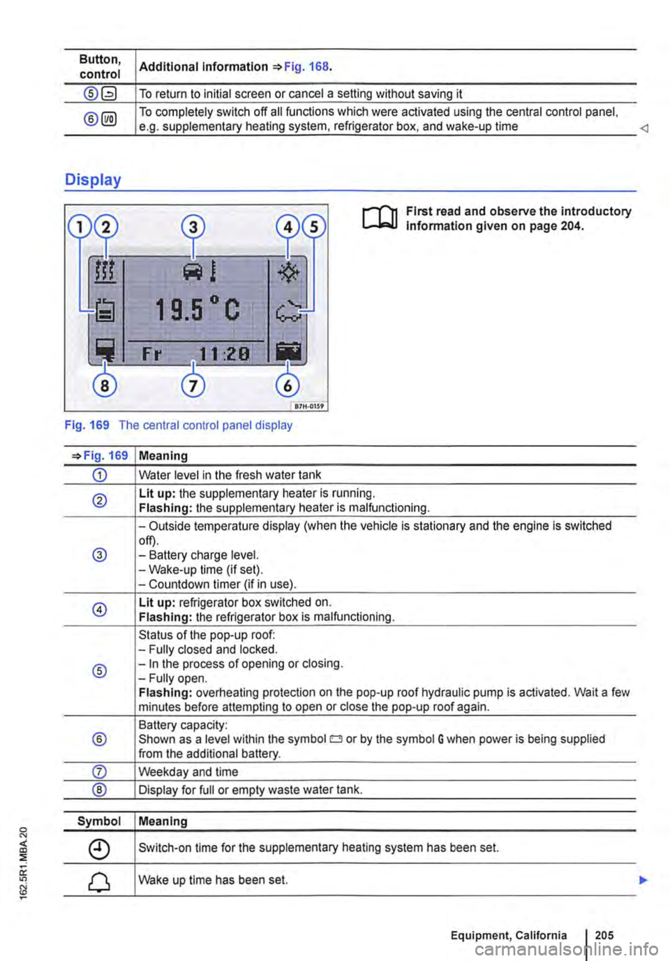
Display
®
Additional information =>Fig. 168.
To return to initial screen or cancel a setting without saving it
To completely switch off all functions which were activated using the central control panel, e.g. supplementary heating system, refrigerator box, and wake-up time <1
1 9.5 ° c
Fr f."l11 :28
0
Pj
3
0 117H-01S9
First read and observe the introductory lnfonmation given on page 204.
Fig. 169 The central control panel display
=>Fig. 169 Meaning
CD Water level in the fresh water tank
® Lit up: the supplementary heater is running. Flashing: the supplementary heater is malfunctioning.
-Outside temperature display (when the vehicle is stationary and the engine is switched
@ off). -Battery charge level. -Wake-up time (if set). -Countdown timer (if in use).
@ Lit up: refrigerator box switched on. Flashing: the refrigerator box is malfunctioning.
Status of the pop-up roof: -Fully closed and locked.
® -In the process of opening or closing. -Fully open. Flashing: overheating protection on the pop-up roof hydraulic pump is activated. Wait a few minutes before attempting to open or close the pop-up roof again.
Battery capacity:
® Shown as a level within the symbol o or by the symbol G when power is being supplied from the additional battery.
Symbol Meaning
Switch-on time for the supplementary heating system has been set.
Wake up time has been set.
Equipment, California 1205
Page 246 of 486
Inserting the Euro plug
• Plug the Euro plug into the Euro socket. The child safety function will disengage at the same time. Electricity will not flow until the child lock has been unlocked.
• Push the Euro plug all the way into the Euro socket so that it is firmly in place and will not fall out as a result of vibration or other vehicle motion.
LEDs above the socket
Constant green light The child lock is disen-gaged. The Euro socket is ready for use.
Flashing red light A fault has occurred. for example cut-off due to excess current or tem-perature.
Compatible devices
Electrical devices with a Euro plug can be connec-ted to the 230-volt Euro socket in the side trim pan-el behind the left front seat.
230-volt grounded safety socket
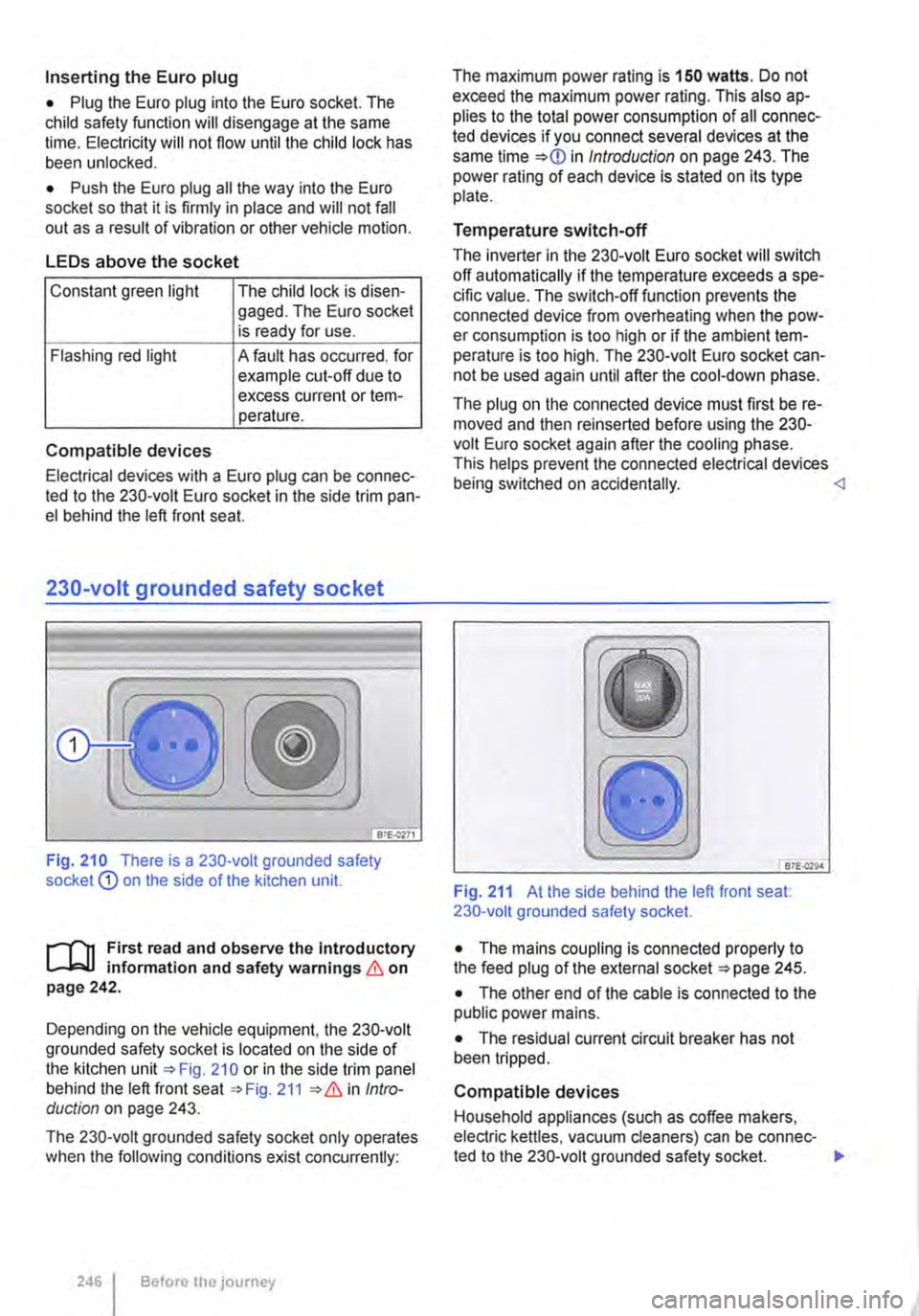
Fig. 210 There is a 230-volt grounded safety socket Q) on the side of the kitchen unit.
r--T'n First read and observe the Introductory L-k.U information and safety warnings & on page 242.
Depending on the vehicle equipment, the 230-volt grounded safety socket is located on the side of the kitchen unit 210 or in the side trim panel behind the left front seat 211 Intro-duction on page 243.
The 230-volt grounded safety socket only operates when the following conditions exist concurrently:
246 I Before the journey
The maximum power rating is 150 watts. Do not exceed the maximum power rating. This also ap-plies to the total power consumption of all connec-ted devices if you connect several devices at the same time in Introduction on page 243. The power rating of each device is stated on its type plate.
Temperature switch-off
The inverter in the 230-volt Euro socket will switch off automatically if the temperature exceeds a spe-cific value. The switch-off function prevents the connected device from overheating when the pow-er consumption is too high or if the ambient tem-perature is too high. The 230-volt Euro socket can-not be used again until after the cool-down phase.
The plug on the connected device must first be re-moved and then reinserted before using the 230-volt Euro socket again after the cooling phase. This helps prevent the connected electrical devices being switched on accidentally. <1
B7E.Q29.4
Fig. 211 At the side behind the left front seat: 230-volt grounded safety socket.
• The mains coupling is connected properly to the feed plug of the external socket 245.
• The other end of the cable is connected to the public power mains.
• The residual current circuit breaker has not been tripped.
Compatible devices
Household appliances (such as coffee makers, electric kettles, vacuum cleaners) can be connec-ted to the 230-volt grounded safety socket. .,.
Page 255 of 486
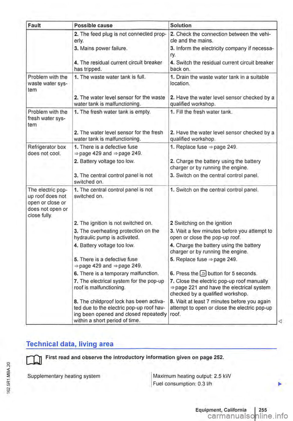
Fault Possible cause Solution
2. The feed plug is not connected prop-2. Check the connection between the vehi-erly. cle and the mains.
3. Mains power failure. 3. Inform the electricity company if necessa-ry.
4. The residual current circuit breaker 4. Switch the residual current circuit breaker has tripped. back on.
Problem with the 1. The waste water tank is full. 1. Drain the waste water tank in a suitable waste water sys-location. tem
2. The water level sensor for the waste 2. Have the water level sensor checked by a water tank is malfunctioning. qualified workshop.
Problem with the 1. The fresh water tank is empty. 1. Fill the fresh water tank. fresh water sys-tem
2. The water level sensor for the fresh 2. Have the water level sensor checked by a water tank is malfunctioning. qualified workshop.
Refrigerator box 1. There is a defective fuse 1. Replace fuse 249. does not cool. 429 and 249.
2. Battery voltage too low. 2. Charge the battery using the battery charger or by running the engine.
3. The central control panel is not 3. Switch on the central control panel. switched on.
The electric pop-1. The central control panel is not 1. Switch on the central control panel. up roof does not switched on. open or close or does not open or close fully.
2. The ignition is not switched on. 2 Switching on the ignition
3. The overheating protection on the 3. Wait a few minutes before you attempt to hydraulic pump is activated. open or close the pop-up roof.
4. Battery voltage too low. 4. Charge the battery using the battery charger or by running the engine.
5. There is a defective fuse 5. Replace fuse 249. 429 and 249.
6. There is a temporary malfunction. 6. Press the button for 5 seconds.
7. The electrical system for the pop-up 7. Close the electric pop-up roof manually roof is malfunctioning. 221 and have the electrical system checked by a qualified workshop.
8. The child proof lock has been activa-8. Wait at least 7 minutes before you again led due to the electric pop-up roof hav-attempt to open or close the electric pop-up ing been opened and closed repeatedly roof. within a short period of time.
Technical data, living area
cu First read and observe the Introductory information given on page 252.
Supplementary heating system
I
Maximum heating output: 2.5 kW
Fuel consumption: 0.3 lfh
Equipment, California I 255
<3
Page 268 of 486
In all cases the automatic gearbox should be checked by a qualified workshop Immediately.
Overheating of the DSG® dual clutch gearbox
The dual clutch gearbox can overheat when the vehicle pulls off regularly, travels at a crawl for long periods, or in stop and go traffic. Gearbox over-heating is indicated by the warning lamp (j) and in some cases by a text message in the instrument cluster display. A signal tone may also be given. Stop the vehicle and allow the gearbox to cool down
The vehicle will not move forwards or backwards even though a gear has been selected
If the vehicle will not move in the required direc-tion, the system may have selected the position in-correctly. Depress the brake pedal and reselect the position.
Gear-change indicator
r--f"'n First read and observe the Introductory L-lo:.l.l information and safety warnings & on page 260.
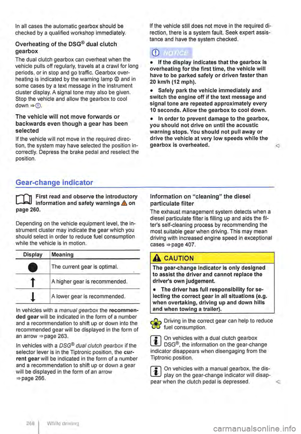
Depending on the vehicle equipment level, the in-strument cluster may indicate the gear which you should select in order to reduce fuel consumption while the vehicle is in motion.
Display Meaning
• The current gear is optimal.
f A higher gear is recommended.
! A lower gear is recommended.
In vehicles with a manual gearbox the recommen-ded gear will be indicated in the form of a number and a recommendation to shift up or down into the recommended gear will be displayed in the form of an arrow 263.
In vehicles with a OSG® dual clutch gearbox if the selector lever is in the Tiptronic position, the cur-rent gear will be indicated in the form of a number and a recommendation to shift up or down a gear will be displayed in the form of an arrow 266.
268 While driving
If the vehicle still does not move in the required di-rection, there is a system fault. Seek expert assis-tance and have the system checked.
CD
• If the display Indicates that the gearbox Is overheating for the first time, the vehicle will have to be parked safely or driven faster than 20 kmlh (12 mph).
• Safely park the vehicle immediately and switch the engine off if the text message and signal tone are repeated approximately every 10 seconds. Allow the gearbox to cool down.
• In order to prevent damage to the gearbox, you should not drive on until the acoustic warning stops. You should not pull away or drive the vehicle at very low speeds while the gearbox is overheated.
The exhaust management system detects when a diesel particulate filter is filling up and aids the fil-ter's self-cleaning process by recommending the most suitable gear when driving. This may mean driving with Increased engine speed in exceptional cases 407.
A CAUTION
The gear-change Indicator Is only designed to assist the driver and cannot replace the driver's own judgement.
• The driver has full responsibility for se-lecting the correct gear In all situations (e.g. when overtaking, driving up and down hills and when towing a trailer).
Driving in the correct gear can help to reduce fuel consumption.
m On vehicles with a dual clutch gearbox W DSG®, the information on the gear-change indicator disappears when disengaging from the Tiptronic position.
m On vehicles with a manual gearbox, the dis-W play on the gear-change indicator will disap-pear when the clutch pedal is depressed.
Page 275 of 486
The Automatic Post-Collision Braking System only functions in frontal, side and rear collisions if the airbag control unit registers the corresponding trig-gering threshold during the accident, and the acci-dent occurs at a speed greater than 10 km/h (6 m ph).
The ESC brakes the vehicle automatically, provi-ded that the hydraulic braking system, the ESC and the electrical system are undamaged in the accident and remain functional.
The following actions override automatic braking in the event of an accident:
• When the driver depresses the accelerator. No automatic braking occurs.
• When the brake pressure transmitted through the depressed brake pedal is greater than the brake pressure provided by the system. The vehi-cle is braked manually.
Anti-lock brake system (ABS)
The ABS prevents the wheels from locking when the brakes are applied up until the point where the vehicle is nearly stationary and assists the driver in steering the vehicle and keeping it under control. This means that the vehicle is less likely to spin, even when the brakes are depressed fully:
• Depress and hold the brake pedal with force. Do not take your foot off the brake pedal or reduce the force on the brake pedal.
• Do not pump the brake pedal or reduce the pressure on the brake pedal.
• Steer the vehicle while the brake pedal is fully depressed.
• The ABS will switch off when the brake pedal is released or if the pressure on the brake pedal is reduced.
If the ABS is taking corrective action, there is a pulsing movement in the brake pedal and some noise. However, ABS will not necessarily guaran-tee shorter braking distances in a// conditions. The braking distance could even be longer when brak-ing on gravel or on fresh snow covering an icy or slippery surface.
Brake Assist system (BAS)
The Brake Assist system can help to reduce the braking distance. The Brake Assist system reinfor-ces brake pressure when the driver depresses the brake pedal quickly in an emergency situation. As a result, full braking power is made accessible very quickly, braking power is reinforced and the brak-ing distance reduced. This means that the ABS is activated more quickly and more effectively.
Do not reduce the pressure on the brake pedal. The Brake Assist system will switch off the brake servo automatically when the brake pedal is re-leased or if the pressure on the brake pedal is re-duced.
Traction control system (TCS)
The TCS reduces the engine output if wheels pin occurs and adapts the output to suit road surface conditions. TCS helps the car to start moving, ac-celerate and climb gradients in unfavourable road conditions.
The TCS can be switched on and off manually 276.
Electronic differential lock (EDL)
The EDL is available for normal driving on straight roads. EDL brakes the wheel that has lost traction and distributes the driving force to the other drive wheels. To prevent the disc brake of the braked wheel from overheating, the EDL cuts out automat-ically if subjected to excessive loads. The EDL will switch on again automatically when the brake has cooled down.
A WARNING
Driving fast on icy, slippery or wet roads can lead to a loss of control of the vehicle and could cause serious injury to the driver and passengers.
• Always adapt your speed and driving style to suit visibility, weather, road and traffic con-ditions. Do not Jet the extra safety afforded by the brake support systems ABS, BAS, EDL, TCS and ESC tempt you into taking any risks when driving.
• The Intelligent technology of the brake support systems cannot overcome the Jaws of physics or system-related vehicle limita-tions. Slippery and wet roads will remain dan-gerous, even when the ESC and other sys-tems are active.
• Driving too fast on wet roads can cause the wheels to Jose contact with the road sur-face and aquaplane. The vehicle cannot be braked, steered or controlled once it has lost contact with the road surface.
• Brake support systems cannot prevent an accident if, for example, you are driving too close to the vehicle in front or are driving too fast for the individual situation. .,.
Starting the engine, changing gear and parking 275
Page 371 of 486
A wARNING
New tyres will have to be run in as they will Initially have reduced grip and braking effect.
• Drive particularly carefully for the first 600 km in order to prevent accidents and se-rious injury.
A WARNING
Wheels must have the necessary freedom of operation. If the wheels do not have the nec-essary freedom of operation, the tyre could rub on parts of the running gear, the vehicle body and the brake lines. This can lead to a fault in the brake system and to tread separa-tion and thus to a tyre bursting.
Tyre pressure
r-T'n First read and observe the introductory L-k.U Information and safety warnings & on page 367.
The correct tyre pressure for factory-fitted tyres is shown on the tyre pressure label and applies to all-season, summer and winter tyres. The tyre pres-sure label is located on the lock column on the left front door.
If the tyre pressure is too low or too high, the tyres will wear prematurely and the vehicle will not han-dle well => &. The correct tyre pressure is particu-larly important at high speeds. Incorrect tyre pres-sure causes premature wear and can cause a tyre burst.
The pressure should therefore be checked at least once a month and before starting a journey.
The given tyre pressure applies to cold tyres. Tyre pressure is always higher in warm tyres than it is in cold tyres.
For this reason, never reduce the pressure in warm tyres to adjust the tyre pressure. This would result in low tyre pressures that could potentially cause the tyre to burst suddenly.
Checking tyre pressure
Always check the tyre inflation pressure on "cold" tyres. A "cold" tyre can be defined as one on a ve-hicle that has only been driven a few kilometres (miles) within 3 hours prior to the test and at low speeds.
A WARNING (Continued)
• The actual tyre size must not exceed the tyre dimensions of manufacturers approved by Volkswagen Commercial Vehicles and must not rub on any vehicle body parts.
m Despite identical size details, the actual size L!..J of the various tyre makes may vary from these specified dimensions, or the tyre contours may vary considerably.
m Volkswagen Commercial Vehicles-approved L!..J tyres are guaranteed to have the dimensions that are suitable for the vehicle. The salesperson will have to provide a certificate from the tyre man-ufacturer for other tyre makes to prove that the tyre is also suitable for the vehicle. This certificate must be stored in a safe place in the vehicle.
• The tyre pressures must be adjusted to suit a heavy vehicle load.
• After altering the tyre pressures, please ensure that the valve caps are screwed on and observe any information and instructions on setting the tyre monitoring system =>page 318.
The temporary spare wheel is filled to the highest tyre pressure permissible for the vehicle.
A WARNING
Too high or too low a pressure may cause the tyre to suddenly lose pressure or burst while the vehicle is in motion. This can cause seri-ous accidents and fatal Injuries.
• If the tyre pressure Is too low, it is possi-ble that the tyre temperature will increase to such an extent when driving that the tread peels off and the tyre bursts.
• Fast speeds or overloading of the vehicle can cause overheating, sudden tyre damage including tyre bursts and ripping of the tread surface and thus to a loss of control of the vehicle.
• If the tyre pressure is too low or too high, the tyres will wear prematurely and the vehi-cle will not handle well. .,.
Wheels and tyres 371
Page 409 of 486
• Use unleaded petrol only.
• Do not allow the fuel tank to run empty.
• Do not overfill engine oil 353.
• Do not tow-start the vehicle. Use jump leads 443.
If you notice misfiring, uneven running or loss of power when the vehicle is moving, reduce speed Immediately. The vehicle should be inspected at
Diesel particulate filter
r-f'n First read and observe the Introductory L-J,:,.IJ Information and safety warnings & on page 407.
The diesel particulate filter filters out soot particles in the exhaust gas. The soot particles gather in the filter and are burnt under high temperatures peri-odically (regeneration). Heat produced can warm the engine.
Regeneration can cause noises, light smells and delay in radiator fan irrespective of the outside temperature, even after the engine is switched off.
To assist the regeneration of diesel particle filter, Volkswagen recommends that you avoid making only short journeys. In vehicles with a DSG® dual clutch gearbox the engine speed can increase while the vehicle is being driven. However, the indi-cator lamp • will not light up.
Observe the following points to ensure that the ex-haust system and the diesel particulate filter will work properly for a long time:
the nearest qualified workshop. If this happens, un-bumt fuel can enter the exhaust system and es-cape into the atmosphere. The catalytic converter can also be damaged by overheating.
Even when the exhaust purification system is W working perfectly, there may be a smell of sulphur from the exhaust in some conditions. This depends on the sulphur content of the fuel being used. <1
• Only use diesel with low sulphur levels 343.
• Never use biodiesel, petrol or heating oil.
• Do not allow the fuel tank to run empty.
• Do not overfill engine oil 353.
• Do not tow-start the vehicle. Use jump leads =page 443.
Even when the exhaust purification system is W working perfectly, there may be a smell of sulphur from the exhaust in some conditions. This depends on the sulphur content of the fuel being used.
m Note for courier vehicles: vehicles with diesel l!J particulate filter are identified accordingly with
Vehicle care and maintenance 409
Page 428 of 486
A WARNING (Continued)
• Always follow the instructions In the checklist and observe the general safety pro-
Sealing and inflating tyres
r-"'('n First read and observe the Introductory L-J,.:.U Information and safety warnings & on page 425.
Sealing a tyre
• Unscrew the cap from the tyre valve.
• Use the valve core extractor 302 CD to screw the valve core out of the tyre valve. Place the core on a clean surface.
• Shake the tyre filler bottle 302 ® vigo-rously up and down several times.
• Screw the filler hose 302 @tightly onto the tyre filler bottle in a clockwise direction. The plastic foil on the plug is pierced automatically.
• Remove the plug from the filler hose 302@ and place the open end fully on the tyre valve.
• Hold the bottle upside down and inject the en-tire contents of the tyre filler bottle into the tyre.
• Remove the empty tyre filler bottle from the valve.
• Use the valve core extractor 302 CD to screw the valve core back onto the tyre valve.
Inflating the tyre
• Screw the tyre filler hose 302 ® of the air compressor tightly onto the tyre valve.
• Check that the bleed screw 302 (?) is closed.
• Start the engine and let it run.
• Insert the plug 302 ®into one of the ve-hicle's 12-volt sockets 163.
• Use the on/off switch 302 ®to switch on the air compressor.
• Run the compressor until the tyre pressure has reached 2.0-2.5 bar (29-36 psi I 200-250 kPa) maximum running time is 6 minutes
• Switch off the air compressor.
• If a pressure level of 2.0-2.5 bar (29-36 psi I 200 -250 kPa) cannot be achieved unscrew the tyre filler hose from the tyre valve.
428 I If and when
• Drive (or reverse) the vehicle approximately 1 0 metres so that the sealing compound is more evenly distributed in the tyre.
• Screw the tyre filler hose for the air compressor firmly back onto the tyre valve and inflate the tyre again.
• If the required pressure still cannot be reached, the tyre is too badly damaged. The tyre cannot be sealed with the breakdown set. Do not drive on. Seek expert assistance &.
• Disconnect the air compressor and unscrew the tyre filler hose from the tyre valve.
• Drive the vehicle no faster than 80 km/h (50 mph) once a tyre pressure of 2.0-2.5 bar (29-36 psi I 200-250 kPa) has been reached.
• Check the tyre pressure after driving for 10 mi-nutes 429.
A WARNING
The tyre filler hose and the air compressor can get hot during Inflation.
• Protect your hands and skin from the hot components.
• Do not place the hot tyre filler hose or the hot air compressor on any Inflammable mate-rials.
• Allow the device to cool down fully before stowing.
• If the tyre will not Inflate to at least 2.0 bar (29 psi/ 200 kPa), the tyre Is too damaged. The sealant Is unable to seal the tyre. Do not drive on. Seek expert assistance.
CD
Switch the air compressor off after a maximum of 6 minutes to avoid overheating. Let the air compressor cool down for a few minutes be-fore switching it back on.