air condition VOLVO 960 1982 Service Repair Manual
[x] Cancel search | Manufacturer: VOLVO, Model Year: 1982, Model line: 960, Model: VOLVO 960 1982Pages: 168, PDF Size: 54.28 MB
Page 108 of 168
70019401960 Specifications
Section 2 B
6304 Engine
General
Group 26 Cooling System
128187
General
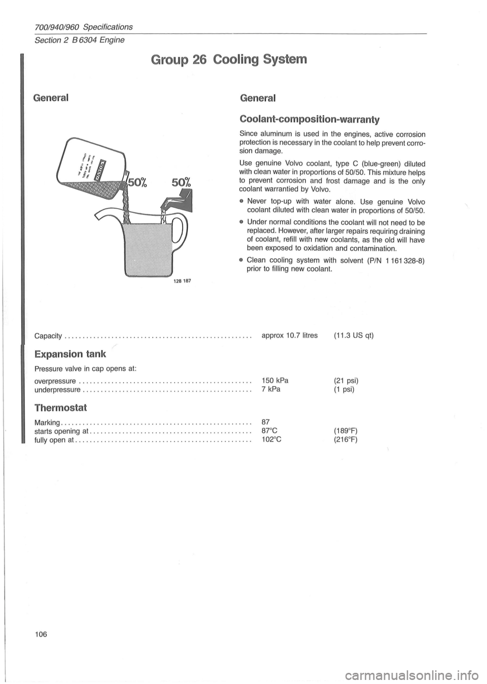
Coolant-com position-warranty
Since aluminum is used in the engines, active corrosion
protection
is necessary in the coolant to help prevent corro
sion damage ,
Use genuine
Volvo coolant, type C (blue-green) diluted
with clean water in proportions of 50/50, This mixture helps
to prevent corrosion and frost damage and is the only
coolant
warrantied by Volvo,
•
Never top-up with water alone, Use genuine Volvo
coolant diluted
with clean water in proportions of 50/50,
• Under normal conditions the coolant will not need to be
replaced, However, after larger repairs requiring draining
of coolant, refill with new coolants, as the old will have
been exposed
to oxidation and contamination ,
• Clean cooling system with solvent (PIN 1161328-8)
prior to
filling new coolant.
Capacity, , , , , , , , . , , , , , , , , , , , , , , , , , , , . , , , , , , , , , . , , . , , , , . , , . , , approx 10,7 litres (11,3 US qt)
Expansion tank
Pressure valve in cap opens at:
overpressure , , , , , , , , , , , , , , , , , , , , . , , , , , , , , , . , , . , , . , , . , , , , , , , ,
underpressure , , , . , , , , ,
.. , , . , , . , , . , , , . , , . , , . , , . , , , , , . , , , , , , , ,
Thermostat
Marking , , , , , , , , , , , , , , , , , , , , , , , , , , , , , , , , , , , , , , , , , , , , , , , , , , , , ,
starts opening
at, , , , , , , , , , , , , . , , , . , , , , , , , , . , , , , , , , , , , , , , , , , , ,
fully open at, , , , , , , , . , , , , , . , , . , , , . , , . , , . , , . , , , , , , , , , , , . , , . , , ,
106 150
kPa
7 kPa
(21 psi)
(1 psi)
Page 131 of 168
(
1984
Fuse Circuits protected Fuse
num-rating
ber
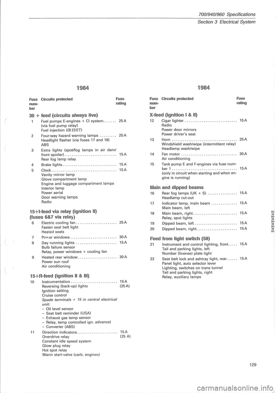
30 + feed (circuit s alw ays live)
Fuel pumps E-engines + CI system ....... (via fuel pump relay)
Fuel i njection ((B 23 ET)
2 Four-way
hazard
warning lamps ......... Headlight flasher (via fuses 17 and 18)
ABS
3 Extra lights (spot/fog lamps in
air dam/ front spoiler) . ................ ... .. ......
Rear fog lamp relay
4 Brake lights .....
.. .............•........
5 C lock ....... ............. ............. ..
Vanity mirror lamp Glove compartment lamp Engine and luggage compartment lamps
Interior lamp Power aerial Door warning lamps
Radio
15+I-feed via relay (ignition II)
(fuses 6&7 via relay)
6 Electric cooling fan ................ ...... Fasten seat belt light Heated seats
7
p()\J\; er windows ........... . •.... ........
8 Day
running
lights ..... .......... ....... Bulb failure sensor Relay, power windows + cooling fan
9 Heated
rear
window ................. ....
Power sun roof Air conditioning
15+R-feed (ignition II & III)
10 Instrumentation ........................ .
Reversing (back-up) lights Ignition setting Cruise control
Spade terminals + 15 in central electrical
unit: -Oil level sensor
-Seat belt reminder (USA) -Exhaust gas temp sensor
-Relay, temp contro lled ign. advance)
-Converter (ABS)
25A
25A
15A
15A
15A
25A
30A
15A
30A
15A (25A)
11 Direction indicators.. .. .... .. . .... .. ..... 15A Overdrive relay (25 A) Constant idle speed system Glow plug relay Hot spot relay Warm start-valve (carb. engines)
70019401960 Specifications
Section
3 Electrical System
1984
Fuse C ircuit s protected Fuse
num-rating
ber
X-feed (ignition I & II)
12 Cigar lighter ...... ..............•....... 15A
Radio
Power door mirrors Power driver's seat
13 Horn ...... ........... .. ................ 25A
Windsh ield wash/wipe (interm ittent relay)
Headlamp wash/wipe
14 Fan motor .................. ......... ... 30A
Air conditioning
15 Tank pump E and F-engines via fuse num-ber 1 ...... ...................... ....... 15A
(only in circuit when starting and when en-
gine is running)
Main and dipped beams
16 Rear fog lamps (UK + S) ................ 15A
Headlamp cut-out
17 Indicator lamp, main beam .............. 15A
Main beam , left
18 Main beam, right .......•... ............. 15A IN
Relay, spot lights "I
19 Dipped beam, left ...... ................. 15A IIII( II.
20 D ipped beam, right ...........•.......... 15A "I II. II
Feed from light switch (58)
21 Instrument and control lighting, front ..... 15A
Tail and parking lights, left Number (license) plate light
22 Seat belt lock and ashtray light, rear ...... 15A
Panel light, auto selector lever Lighting, switches on trans tunnel Tail and parking lights, right Relay, auxiliary lamps
129
Page 135 of 168
(
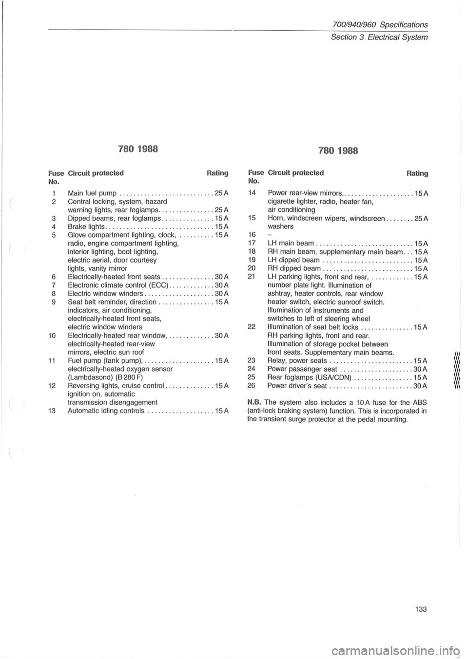
780 1988
Fu se Circuit protected
No.
Rating
1 Main fuel pump ........................... 25 A
2
Central locking, system, hazard
warning
lights, rear fog lamps ................ 25 A
3 Dipped beams, rear
foglamps ............... 15 A
4 Brake
lights .................. ............. 15 A
5
Glove compartment lighting, clock, .......... 15 A
radio, engine compartment
lighting,
interior lighting, boot lighting,
electric aerial,
door courtesy
lights, vanity mirror
6
Electrically-heated front seats ............... 30 A
7
Electronic climate control (ECC) ............. 30 A
8
Electric window winders .................... 30 A
9
Seat belt reminder , direction ................ 15 A
indicators, air conditioning ,
electrically-heated front seats,
electric window winders
10 Electrically-heated rear window, ............. 30 A
electrically -heated rear-view
mirrors,
electric sun roof
11 Fuel pump (tank pi.Jmp), .................... 15 A
electrically-heated oxygen sensor
(Lambdasond)
(B 280 F)
12 Reversing lights, cruise control .. ............ 15 A
ignition on, automatic
transmission disengagement
13 Automatic idling controls ................... 15 A
70019401960 Specifications
Section
3 Electrical System
780 1988
Fu se Circuit protected
No. Rating
14 Power rear-view mirrors, .................... 15 A
cigarette
lighter, radio, heater fan,
air conditioning
15 Horn, windscreen wipers, windscreen ........ 25A
washers
16
17
LH main beam ............................ 15A
18 RH main beam , supplementary main beam ... 15 A
19 LH dipped beam ............. ............. 15A
20 RH dipped beam .......................... 15 A
21 LH parking lights, front and rear, ............ 15 A
number
plate light. Illumination of
ashtray, heater
controls, rear window
heater switch,
electric sunroof switch.
Illumination of instruments and
switches to
left of steering wheel
22 Illumination of seat belt locks ............... 15 A
RH parking lights, front and rear.
Illumination of storage pocket between
front seats.
Supplementary main beams .
23 Relay, power seats ................ .... .... 15 A
24 Power passenger seat .................. ... 30 A
25 Rear fog lamps (USA/CON) ................. 15 A
26 Power driver's seat ................... .. .. . 30 A
N.B. The system also includes a 10 A fuse for the ABS
(anti-lock
braking system) function. This is incorporated in
the transient surge protector at the pedal mounting.
133
·,f' "'I .", '" .",
'" .",
'" .",
Page 162 of 168
700/940/960 Specifications
Section 8 Body and interior
Section 8 Body and interior
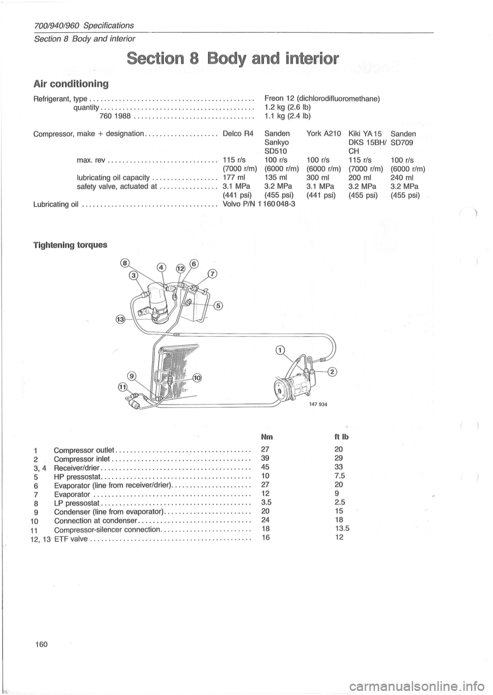
Air condition ing
Refrigerant, type ............ ..................... ........... .
quantity .
........................................ .
7601988 ............ ......... ......... .. .
Compressor, make
+ designation .................... Delco R4
Freon 12 (dichlorodifluoromethane)
1.2 kg (2.6 Ib)
1 .1 kg (2.4lb)
Sanden
York A210 Kiki YA 15 Sanden
Sankyo
OKS 15BHI S0709
S0510
CH
max. rev ......................... . .... 115 rls 100 rls 100 rls 115 rls 100 rls
(7000 rIm) (6000 rIm) (6000 rIm) (7000 rIm) (6000 rIm)
lubricating oil capacity .................. 177 ml 135 ml 300 ml 200 ml 240 ml
safety valve, actuated at ................ 3.1 MPa 3.2 MPa 3.1 MPa
3.2 MPa 3
.2 MPa
(441 psi) (455 psi) (441 psi) (455 psi) (455 psi)
Lubricating
oil . .................................... Volvo PIN 1 160048-3
T ightening torques
Nm ftlb
1 Compressor outlet .................... .' ............... . 27 20
2 Compressor inlet ............................ ......... . 39 29
3, 4 Receiver/drier .............. .......................... . 45 33
5 HP pressostat. ....................................... . 10 7.5
6 Evaporator
(line from receiver/drier) ........... .... ...... . 27 20
7 Evaporator ............. .................... ......... . 12 9
8
LP pressostat ............. ........................ ... . 3.5
2.5
9 Condenser
(line from evaporator) ....................... . 20 15
10 Connection at condenser .............................. . 24 18
11 Compressor-silencer connection ........................ .
12, 13 ETF valve ......... .................................. .
18 13.5
16 12
160
Page 163 of 168
(
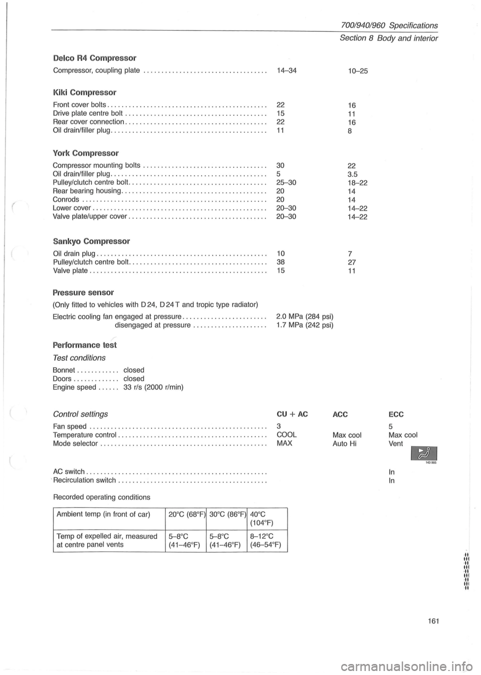
Delco R4 Compressor
Compressor, coupling plate ................................... 14-34
Kiki Compressor
Front cover bolts. . . . . . . . . . . . . . . . . . . . . . . . . . . . . . . . . . . . . . . . . . . . . 22
Drive
plate centre bolt . . . . . . . . . . . . . . . . . . . . . . . . . . . . . . . . . . . . . . . . 15
Rear cover connection. . . . . . . . . . . . . . . . . . . . . . . . . . . . . . . . . . . . . . . .
22
Oil drain/filler plug. . . . . . . . . . . . . . . . . . . . . . . . . . . . . . . . . . . . . . . . . . . . 11
York Compressor
Compressor mounting bolts ........................ .......... .
Oil drain/filler plug ........................................... .
Pulley/clutch centre bolt. ..................................... .
Rear bearing housing
.................................. ...... .
Con rods .
.................................................. .
Lower cover
........................................ .. ...... .
Valve plate/upper cover ...................................... .
Sankyo Compressor
30
5
25-30
20
20
20-30
20-30
Oil drain plug. . . . . . . . . . . . . . . . . . . . . . . . . . . . . . . . . . . . . . . . . . . . . . . . 10
Pulley/clutch
centre bolt. . . . . . . . . . . . . . . . . . . . . . . . . . . . . . . . . . . . . . . 38
Valve plate. . . . . . . . . . . . . . . . . . . . . . . . . . . . . . . . . . . . . . . . . . . . . . . . . . 15
Pressure sensor
(Only fitted to vehicles with D 24, D 24 T and tropic type radiator)
70019401960 Specifications
Section 8 Body and interior
10-25
16
11
16
8
22
3.5
18-22
14
14
14-22
14-22
7
27
11
Electric cooling fan engaged at pressure ....................... .
disengaged at pressure
.................... .
2.0 MPa (284 psi)
1 .7 MPa (242 psi)
Performance test
Test conditions
Bonnet . . . . . . . . . . .. closed
Doors . . . . . . . . . . . .. closed
Engine
speed. . . . .. 33 r/s (2000 r/min)
Control settings
Fan speed ........................... ...................... .
Temperature
control . ................................. ....... .
Mode
selector . ............................................. .
AC switch ............. ..................................... .
.
Recirculation switch ......................................... .
Recorded operating conditions
Ambient temp
(in front of car) 20°C (68°F) 30°C (86°F)
40°C
(104 °
F)
Temp of expelled air, measured 5-8°C 5-8°C 8-12°C
CU + AC
3
COOL
MAX
at centre panel vents
(41-46°F) (41-46 °F) (46-54°F)
ACC
Max cool
Auto Hi
ECC
5
Max cool
Vent
-In
In
143985
161
·11 lit ·11 lit ·11 lit ·11 III II