low oil pressure VOLVO 960 1982 Service Repair Manual
[x] Cancel search | Manufacturer: VOLVO, Model Year: 1982, Model line: 960, Model: VOLVO 960 1982Pages: 168, PDF Size: 54.28 MB
Page 19 of 168
(
70019401960 Specifications
Section
2 B 19, B 23 Engines
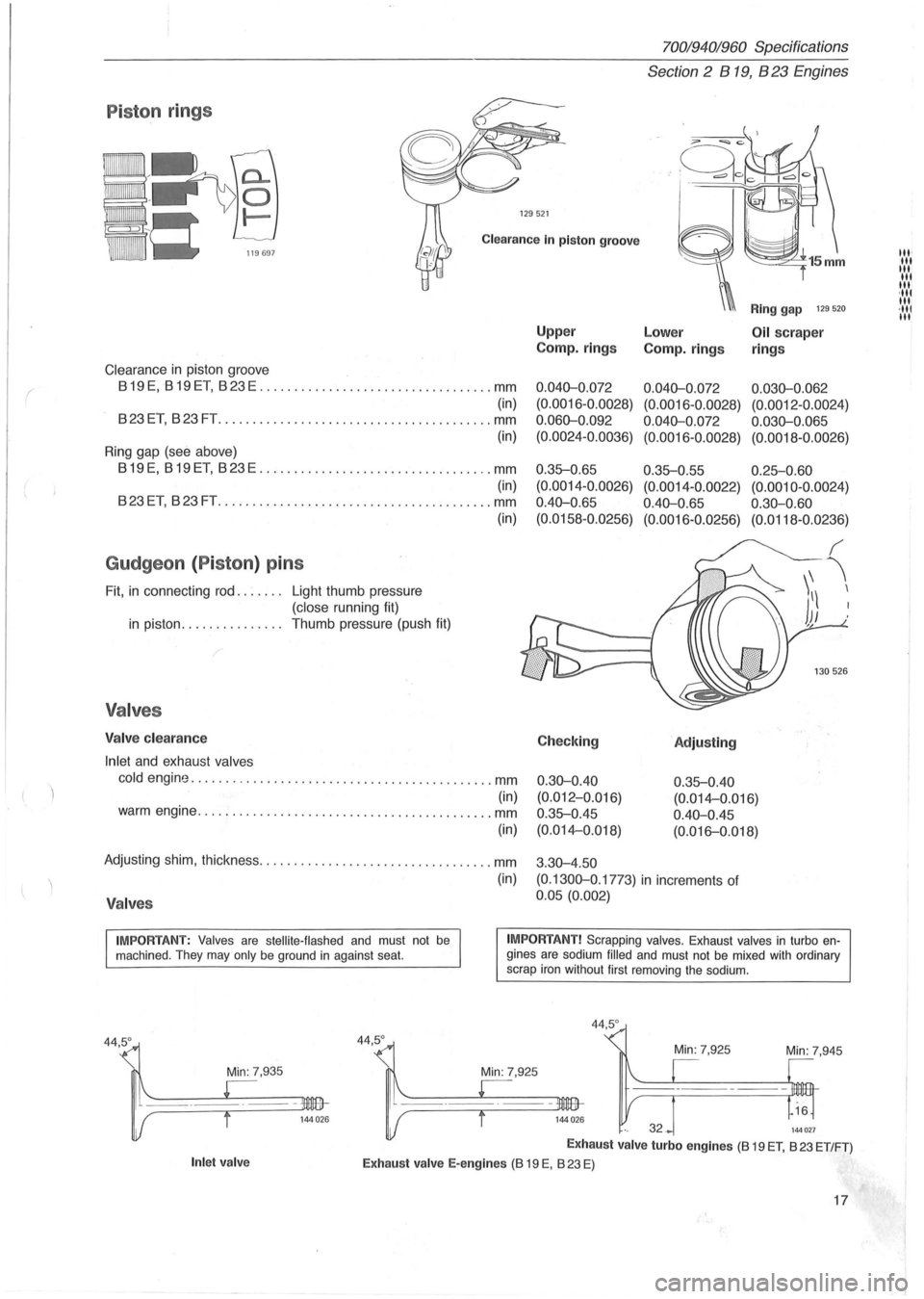
P iston rings
129521
Clearance In piston groove
Clearance in piston groove
819 E, 819 ET, 823 E .................................. mm
(in)
823ET, 823FT .............. .......................... mm
(in)
Ring gap (see above)
819E, 819ET, 823E .................................. mm
(in)
823ET, 823FT ................ .......... .............. mm
Gudgeon (Piston ) pins
Fit, in connecting rod. . . . . .. Light thumb pressure
(close running fit)
in piston. . . . . . . . . . . . . .. Thumb pressure (push fit)
Valves
Valve clearance
Inlet
and exhaust valves
(in)
cold engine ............................................ mm
(in) warm engine ........................................... mm
(in)
Adjusting shim, thickness .................................. mm
(in)
Valves
Upper
Camp.
rings
0.040-0 .072
(0. 0016-0.0028)
0.060-0 .092
(0.0024-0.0036)
0 .35-0.65
(0.0014 -0 .0026)
0.40-0 .
65
(0.0158-0.0256)
Checking
0.30-0.40
(0.012-0.Q16)
0.35-0.45
(0.014-0.018)
3 .
30-4.50
Ring gap 129 520
Lower Oil scraper
Camp.
rings rings
0.040-0.072 0.030-0.062
(0.0016 -0 .0028) (0.0012 -0.0024)
0.040-0.072 0.030-0.065
(0.0016-0.0028) (0.0018-0.0026)
0.35-0.55 0.25-0.60
(0.0014-0.0022) (0.0010-0.0024)
0.40-0.65 0.30-0.60
(0.0016-0.0256) (0.0118-0.0236)
'Adjusting
0.35-0.40
(0. 014-0 .016)
0.40-0.45
(0. 016-0.018)
(0.1300-0 .1773)
in increments of
0.05 (0.002)
IMPORTANT: Valves are stellite-flashed and must not be machined . They may only be ground in against seat. IMPORTANT! Scrapping valves. Exhaust valves in turbo engines are sodium filled and must not be mixed with ordinary
scrap iron without first removing the sodium.
Min: 7,935
Inlet valve
44,5°
44,5 °
Min: 7,945
144027
Exhaust valve turbo engines (8 19 ET, 823 ET/FT)
Exhaust valve E-engines (8 19 E, 823 E)
17
III' III III
III
III ,111 III ·111 III
Page 39 of 168
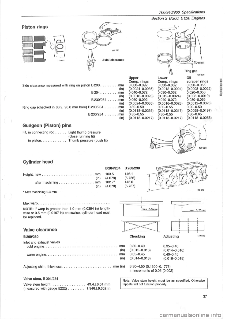
Piston rings
129521
Axial clearance
Side clearance measured with ring on piston 8200 ........... mm
(in)
8204 ........... mm
(in)
8230/234 ....... mm (in)
Ring gap (checked
in 88.9, 96.0 mm bore) 8200/204 ........ mm (in) 8230/234 ........ mm
Gudgeon (Piston) pins
Fit, in connecting rod. . . . . .. Light thumb pressure
(close running fit) (in)
in piston.
. . . . . . . . . . . . .. Thumb pressure (push fit)
Cylinder head-
Height, new ............................... mm
(in)
after machining
..................... mm
(in)
• Max machining 0.3 mm
B204/234
103.5
(4.078)
102.7*
(4.078)
Max warp .......................................... .
NOTE: If warp is greater than 1.0 mm (0.0394 in) length
wise or 0.5 mm (0.0197 in) crosswise, cylinder head must
be replaced.
Valve clearance
B200/230
Inlet and exhaust valves
cold
engine ............................................ mm
(in)
warm engine
........................................... mm
(in)
70019401960 Specifications
Section 2 B 200, B 230 Engines
Upp er Compo rings 0.060-0.092
(0.0024-0.0036)
0.040-0.072 (0.0016-0.0028)
0.060-0.092 (0.0024-0.0036)
0.30-0.50
(0.0118--0.0236)
0.30-0.55
(0.0118--0.0217)
B200/230
146.1
(5.756)
145.6
(5.737)
Checking
0.30-0.40 (0.012-0.Q16)
0.35--0.45 (0.014-0.018)
Lower Compo rings 0.030-0.062 (0.0012-0.0024)
0.030-0.062 (0.012-0.0024)
0.040-0.072 (0.0016-0.0028)
0 .30-0.55
(0.0118--0.0217)
0.30-0.55
(0.0118--0.0217)
Adjusting
0.35--0.40
(0.014-0.016)
0.40-0.45 (0.016-0.018)
Ring gap 129520 Oil scraper rings 0.020-0.055
(0.0008--0.0022)
0.020-0.050 (0.008--0.0019)
0.030-0.065 (0.0012-0.0026)
0.20-0.50 (0.0098--0.0197)
0.30-0.65 (0.0118--0.0256)
max o 25mm
129 826
Adjusting shim, thickness .............................. mm (in) 3.30-4.50 (0.1300-0.1773)
in increments of 0.05 (0.002)
Valve stem, B 204/234
Valve stem height . . . . . . . . . . . . . . . . . . .. 49.4±0.04 mm
(measured with gauge 5222) . . . . . . . . .. 1.946±0.002 in
Note: Valve stem height must be as specified. Otherwise
tappets will not function properly.
37
III III
ill III ill
IN liN
t·
Page 66 of 168
700/940/960 Specifications
Section 2' 8200,8230 Engines
Group 25 Intake and exhaust systems
Turbo engines
'-198~
Engine type .... ; ......... . , ............ .. .............
Charg~ pressure, at full load and ................... r/min
checking
.. ................... kPa (psi)
setting. . . . . . . . . . . . . . . . . . . . .
.. kPa (psi)
Charge air overpressure, switch opens at ....... kPa
(psi)
Charge air pressure, switch closes at ........... kPa (psi)
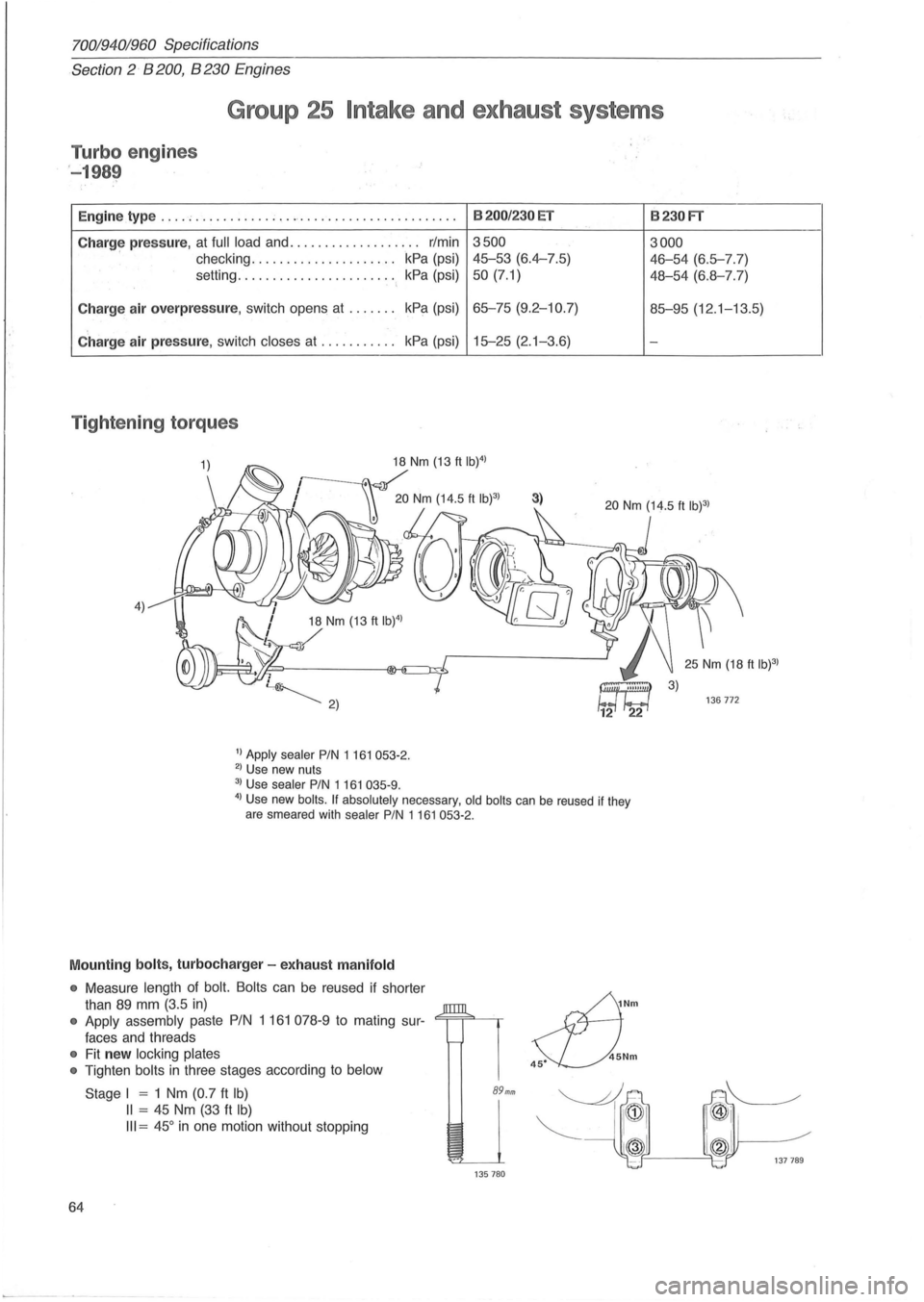
Tightening torques
4) 18 Nm (13 ft IW)
/
1) Apply sealer PIN 1 161 053-2. 2) Use new nuts
3) Use sealer PIN 1161 035-9.
8200/230 ET
3500
45-53 (6.4-7.5)
50 (7.1)
65-75 (9.2-10.7)
15-25 (2. 1-3.6)
3)
4) Use new boils. If absolutely necessary, old boils can be reused if they
are smeared with sealer PIN 1161053-2.
Mounting bolts, turbocharger -exhaust manifold
• Measure length of bolt. Bolts can be reused if shorter
than
89 mm (3.5 in)
• Apply assembly paste PIN 1 161 078-9 to mating sur-<=;==;=""-~
faces and threads
• Fit new locking plates
•
Tighten bolts in three stages according to below
64
Stage I = 1 Nm (0.7 ft Ib)
II = 45 Nm (33 ft Ib)
III = 45° in one motion without stopping
89mm
135780
~Nm
s::L).Nm
8230FT
3000
46-54 (6.5-7.7)
48-54 (6.8-7.7)
85-95 (12 .1-13.5)
-
136772
Page 76 of 168
70019401960 Specifications
Section
2 B 28 Engine
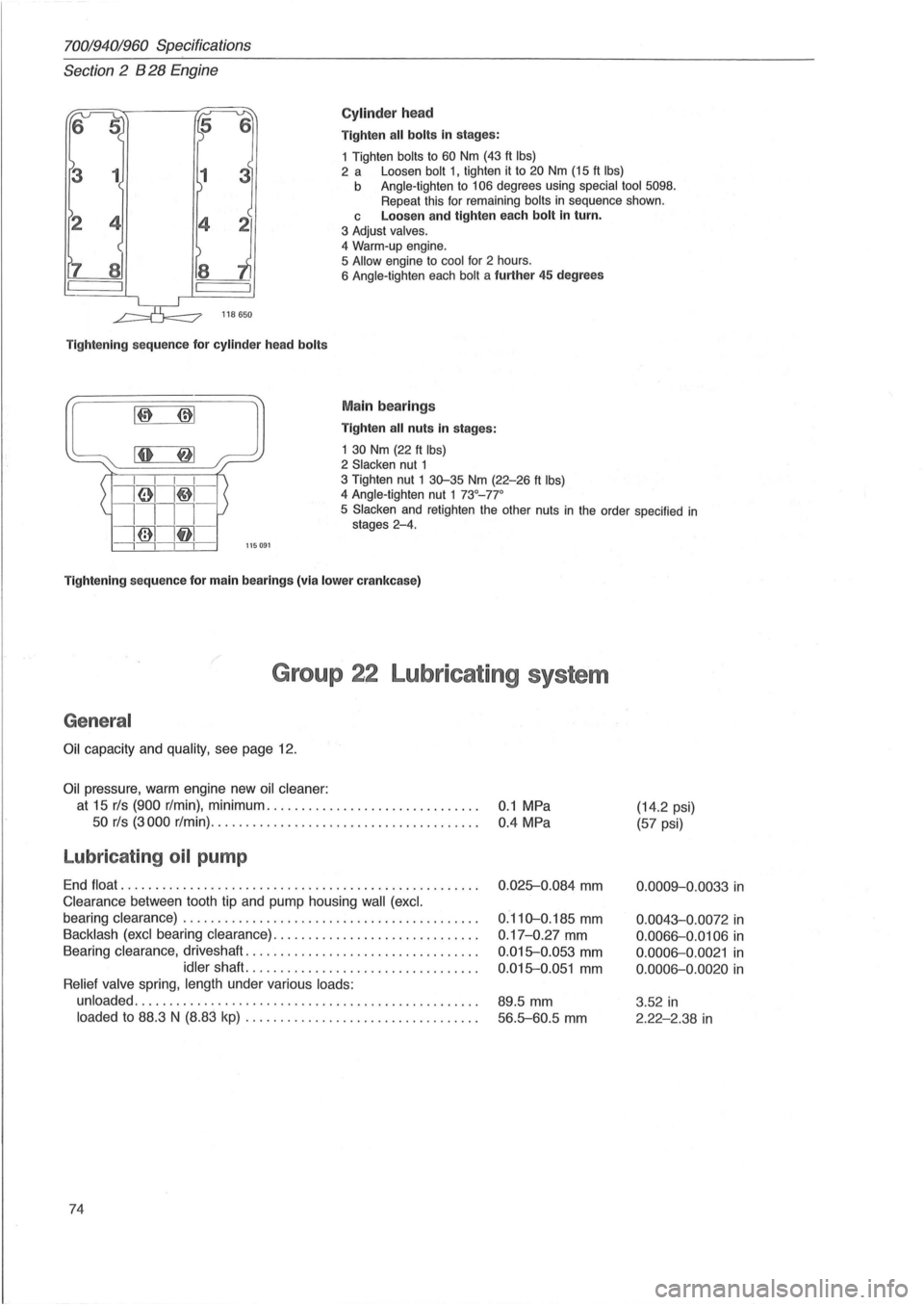
Cylinder head
Tighten all bolts in stages:
1 Tighten
bolts to 60 Nm (43 ft Ibs) 2 a Loosen bolt 1, tighten it to 20 Nm (15 ft Ibs) b Angle-tighten to 106 degrees using special tool 5098. Repeat this for remaining bolts in sequence shown.
118650
Tightening sequence for cylinder head bolts
L~~::~:~' ~I ~: I I I I
i61I~-
c Loosen and tighten each bolt in turn.
3 Adjust valves.
4
Warm-up engine.
5 Allow engine to cool for 2 hours.
6 Angle-tighten each bolt a further 45 degrees
Main bearings
Tighten all nuts in stages:
1
30 Nm (22 ft Ibs) 2 Slacken nut 1 3 Tighten nut 1 30-35 Nm (22-26 ft Ibs) 4 Angle-tighten nut 1 73°_77 °
1111-
i@1lf11 -
5 Slacken and retighten the other nuts in the order specified in stages 2-4.
---,---,---,---,-115091
Tightening sequence for main bearings (via lower crankcase)
Group 22 Lubricating system
General
Oil capacity and quality, see page 12.
Oil pressure, warm engine new oil cleaner:
at 15 rls (900 r/min), minimum .............................. .
50 rls (3000 r/min) .......... ....... ......... ............ .
Lubricating oil pump
End float ................................................... .
Clearance between tooth tip and pump housing wall (excl.
bearing clearance) .......................................... .
Backlash (excl bearing clearance) ................ ............. .
Bearing
clearance, driveshaft ................................. .
idler shaft. ................................ .
Relief valve spring, length under various loads:
unloaded
................................................. .
loaded to 88.3 N (8.83 kp) ............ ... .... .............. .
74
0.1 MPa
0.4 MPa
0 .
025-0.084 mm
0.110-0.185 mm
0 .17-0.27 mm
0.015-0.053 mm
0.015-0.051 mm
89.5 mm
56.5-60.5 mm
(14.2 psi)
(57 psi)
0.0009-0.0033 in
0.0043-0.0072 in
0.0066-0.0106 in
0 .0006-0.0021 in
0.0006-0.0020 in
3 .52 in
2.22-2.38 in
Page 101 of 168
(
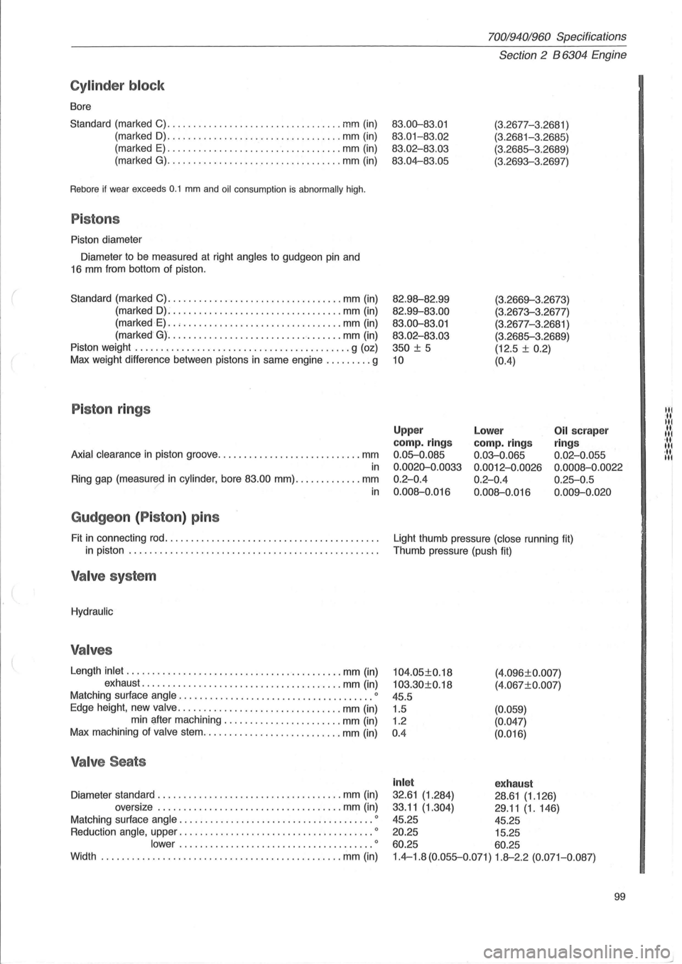
Cylinder block
Bore
Standard (marked C)
........................... ....... mm (in)
(marked
D) ........... ....................... mm (in)
(marked
E) .................................. mm (in)
(marked
G) ................... . .............. mm (in)
Rebore if wear exceeds 0.1 mm and oil consumption is abnormally high.
Pistons
Piston diameter
Diameter to be measured at right
angles to gudgeon pin and
16 mm from bottom of piston.
Standard (marked C)
.................................. mm (in)
(marked
D): ................................ . mm (in)
(marked
E) .. , ........................ ....... mm (in)
(marked
G) ............ ...................... mm (in)
Piston weight
.......................................... g (oz)
Max weight difference between pistons in same engine
......... g
Piston rings
Axial clearance in piston groove ............................ mm
in
Ring gap (measured in cylinder, bore 83.00 mm) ............. mm ? in
Gudgeon (P iston ) pins
Fit in connecting rod ......................................... .
in piston
................................................ .
Valve system
Hydraulic
Valves
Length inlet ...... .................................... mm (in)
exhaust
.............. ......................... mm (in)
Matching surface
angle .................................. .... 0
Edge height, new valve ................................ mm (in)
min after machining .
...................... mm (in)
Max machining of
valve stem ................ ........... mm (in)
Valve Seats
Diameter standard .................................... mm (in)
oversize
.... ................................ mm (in)
Matching surface
angle .......................... ............ 0
Reduction angle, upper ...................................... 0
lower ................. ....... .............. 0
Width ...................................... ... ...... mm (in)
70019401960 Specifications
Section 2 B 6304 Engine
83.00-83.01
83.01-83 .02
83.02-83.03
83.04-83.05
82.98--82.99
82.99--83.00
83.00-83.01
83.02 -83.03
350
± 5
10
(3.2677-3 .2681 )
(3.2681-3.2685)
(3.2685-3 .2689)
(3.2693-3.2697)
(3.2669--3.26 7
3)
(3.2673-3.2677)
(3.2677-3.
2681 )
(3.2685-3.2689)
(12.5 ±
0.2)
(0.4)
Upper
camp. rings
0.05-0.085
0.0020-0.0033
0.2-0.4
0.008--0.016
Lower
camp. rings
0.03-0.065
0.0012-0.0026
0.2-0.4
0.008--0.016
Oil scraper
ring s
0.02-0.055
0.0008 -0.0022
0.25-0.5
0.009--0 .020
Light thumb pressure (close running fit)
Thumb pressure (push fit)
104.05±0.18
103.30±0.18
45.5
1.5
1.2
0 .4 (4
.
096±0.007)
(4.067±0. 007)
(0.059)
(0.047)
(0.016)
inl et exhaust
32.61 (1.284) 28.61 (1.126)
33.11
(1.304) 29 .11 (1.146)
45.25 45.25
20.25 15.25
60.25 60.25
1.4-1.8 (0.055-0.071) 1.8--2.2 (0.071-0.087)
99
Itl
It
Itl
.... 1 '11 Itl ... Itl
Page 141 of 168
70019401960 Specifications -------------------------------------------------------------
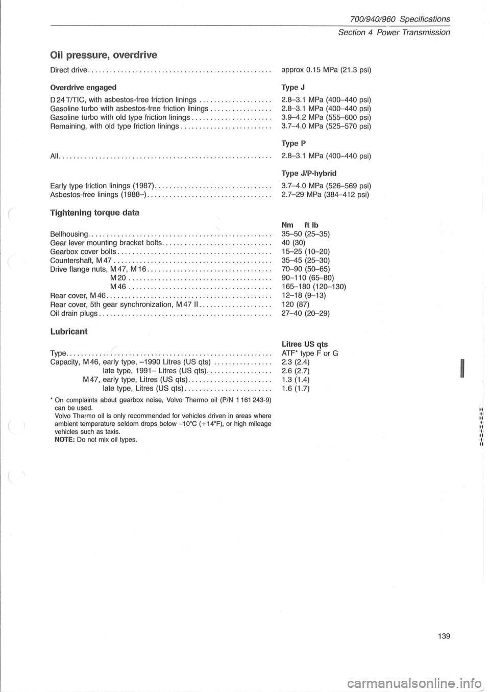
Oil pressure, overdrive
Direct drive .............................................. .. . .
Overdr ive engaged
D 24 TmC, with asbestos-free friction linings ................... .
Gasoline turbo with asbestos-free friction linings ................ .
Gasoline turbo with old type friction linings ..................... .
Remaining, with
old type friction linings ........................ .
All ......................................................... .
Early type friction linings (1987) ............................... .
Asbestos -
free linings (1988-) ................................. .
( Tightening torque data
8ellhousing ................................................. .
Gear
lever mounting bracket bolts ............................. .
Gearbox cover
bolts ......................................... .
Countershaft, M 47
.......................................... .
Drive
flange nuts, M 47, M 16 ................................. .
M20 ...................................... .
M46 ...................................... .
Rear cover, M 46
............................................ .
Rear cover,
5th gear synchronization, M 47 II ................... .
Oil drain plugs .............................................. .
Lubricant
/ Type ....................................................... .
Capacity, M46,
early type, -1990 Litres (US qts) ............... .
late type, 1991-Litres (US qts) ................. .
M
47, early type, Litres (US qts) ...................... .
late type, Litres (US qts) ....................... .
• On complaints about gearbox noise, Volvo Thermo oil (PIN 1161 243-9) can be used. Volvo Thermo oil is only recommended for vehicles driven in areas where
ambient temperature seldom drops below -10°C (+14°F), or high mileage vehicles such as taxis. NOTE: Do not mix oil types.
Section 4 Power Transmission
approx 0.15 MPa (21.3 psi)
Type J
2.8--3.1 MPa (400-440 psi)
2.8--3.1 MPa (400-440 psi)
3.9-4.2
MPa (555-600 psi)
3.7-4.0
MPa (525-570 psi)
Type P
2.8--3.1 MPa (400-440 psi)
Type J/P-hybrid
3.7-4.0 MPa (526-569 psi)
2.7-29
MPa (384-412 psi)
Nm ft Ib
35-50 (25-35)
40 (30)
15-25 (10-20)
35-45 (25-30)
70-90 (50-65)
90-110
(65-80)
165-180
(120-130)
12-18 (9-13)
120 (87)
27-40 (20-29)
Litres U S qts
ATF* type F or G
2 .3 (2.4)
2.6 (2.7)
1.3 (1.4)
1.6 (1.7)
139
I
.til I! II I! II I! ·1 , I!
Page 143 of 168
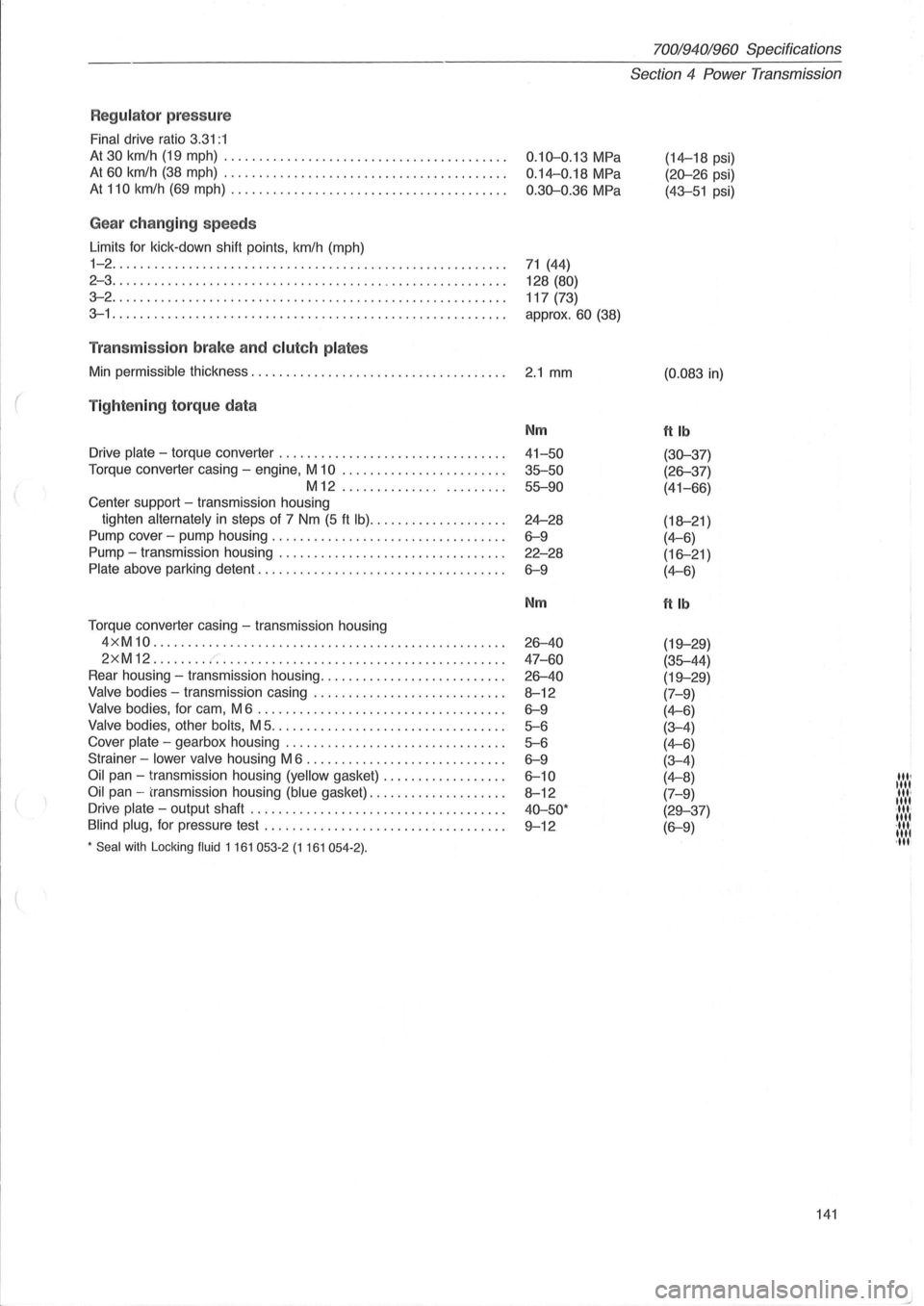
Regulator press ure
Final drive ratio 3.31:1
At 30 km/h (19 mph) ........................................ .
At 60 km/h (38 mph) ....... ................................. .
At 110 km/h (69 mph) ....................................... .
Gea r ch anging speeds
Limits for kick -down shift points , km/h (mph)
1-2 ........................................................ .
2 - 3
......... ............................................... .
3-2 ............................. ........................... .
3-1 ...................................................... .. .
Tran smiss io n brake an d clut ch pla tes
Min permissible thickness .................................. .. .
( Tig ht enin g to rq ue da ta
Drive plate - torque converter ....................... ......... .
Torque converter casing -engine, M
10 ....................... .
M12 ..................... ..
Center support -transmission housing
tighten
alternately in steps of 7 Nm (5 ft Ib) ................... .
Pump cover -pump housing
.................. ............... .
Pump -transmission housing ...
............................. .
Plate above parking detent ............................ .... ... .
Torque converter casing -transmission housing
4 x M
10 .................................................. .
2xM12 ....... . r. ............... ......................... .
Rear housing -transmission housing .......................... .
Valve bodies -transmission casing ........................... .
Valve bodies, for cam, M 6 ................................... .
Valve bodies, other bolis, M 5 ................................. .
Cover
plate - gearbox housing ............................... .
Strainer -
lower valve housing M 6 ......................... ... .
Oil pan - transmission housing (yellow gasket) ................. .
Oil pan -transmission housing (blue gasket) ................... .
Drive
plate - output shaft .... ............................. ... .
Blind plug, for pressure test ....................... .. ......... .
* Seal with Locking fluid 1 161 053-2 (1 161 054-2) .
0.10-0.13 MPa
0.14-0.18 MPa
0.30-0.36 MPa
71 (44)
128
(80)
117 (73)
approx.
60 (38)
2.1 mm
Nm
41-50
35-50 55-90
24-28
6-9
22-28
6-9
Nm
26-40
47 -60
26-40
8-12
6-9
5-6
5-6
6-9
6-10
8-12
40-50·
9-12
70019401960 Specifications
Section 4 Power Transmission
(14-18 psi)
(20-26 psi)
(43-51 psi)
(0.083 in)
ftlb
(30-37)
(26-37)
(41-66)
(18-21 )
(4-6)
(16-21)
(4-6)
ftlb
(19-29)
(35-44)
(19-29)
(7-9)
(4-6)
(3-4)
(4-6)
(3-4)
(4-8)
(7-9)
(29-37)
(6-9)
141
'", "" '", "" ·11"
"" ·11.· 1111 ,11'
Page 147 of 168
(
(
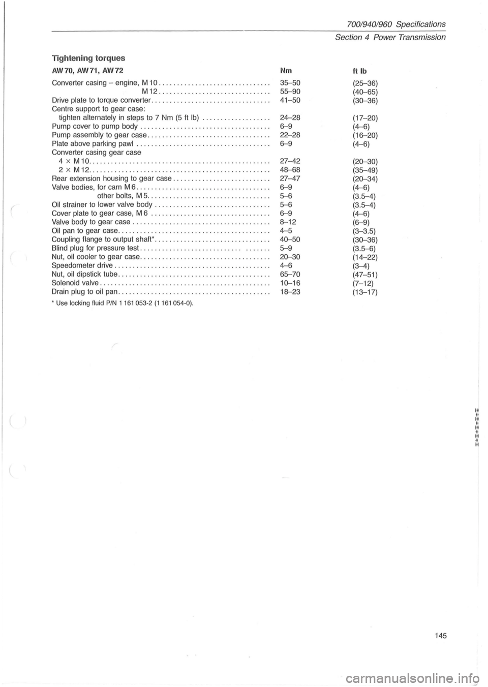
Tightening torques
AW70, AW71, AW72
Converter casing -engine, M 10 ...................... .. ...... .
M12 .................. ......... .. . .
Drive plate
to torque converter ................... ............. .
Centre support to gear case:
tighten alternately
in steps to 7 Nm (5 ft Ib) ............... ... .
Pump cover to pump body .......................... ......... .
Pump assembly to gear case .............. ................... .
Plate above parking pawl ............................. ....... .
Converter casing gear case
4
x M 10 ................................ ................. .
2 x M 12 ..
.............. ................................. .
Rear extension housing to gear case
.......................... .
Valve bodies, for cam M 6 .................................... .
other bolts, M 5 ...
.............................. .
Oil strainer to lower valve body ........... .. ............ ...... .
Cover plate
to gear case, M 6 ................................ .
Valve body to gear case ..................... .......... ..... . .
Oil pan to gear case .......... ........ ..................... .. .
Coupling flange
to output shaW .................... ........... .
Blind plug for pressure test. . . . . . . . . . . . . . . . . . . . . . . . . . . . . ..
... .
Nut, oil cooler to gear case .
.................................. .
Speedometer drive
................... .................. ..... .
Nut, oil dipstick tube
........ ................................. .
Solenoid valve
.................... .. ........................ .
Drain plug
to oil pan ........................................ . .
• Use locking fluid PIN 1161 053-2 (1161 054-0) .
Nm
35-50
55-90
41-50
24-28
6-9
22-28
6-9
27-42
48-68
27-47
6-9
5-6
5-6
6-9
8-12
4-5
40-50
5-9
20-30
4-6
65-70
10-16
18-23
70019401960 Specif ications
Section
4 Power Transmission
ftlb
(25-36)
(40-65)
(30-36)
(17-20)
(4-6)
(16-20)
(4-6)
(20-30)
(35-49)
(20-34)
(4-6)
(3.5-4)
(3.5-4)
(4-6)
(6-9)
(3-3.5)
(30-36)
(3.5-6)
(14-22)
(3-4)
(47-51)
(7-12)
(13-17)
145
II
" II ., II ' . .. • • ..
Page 163 of 168
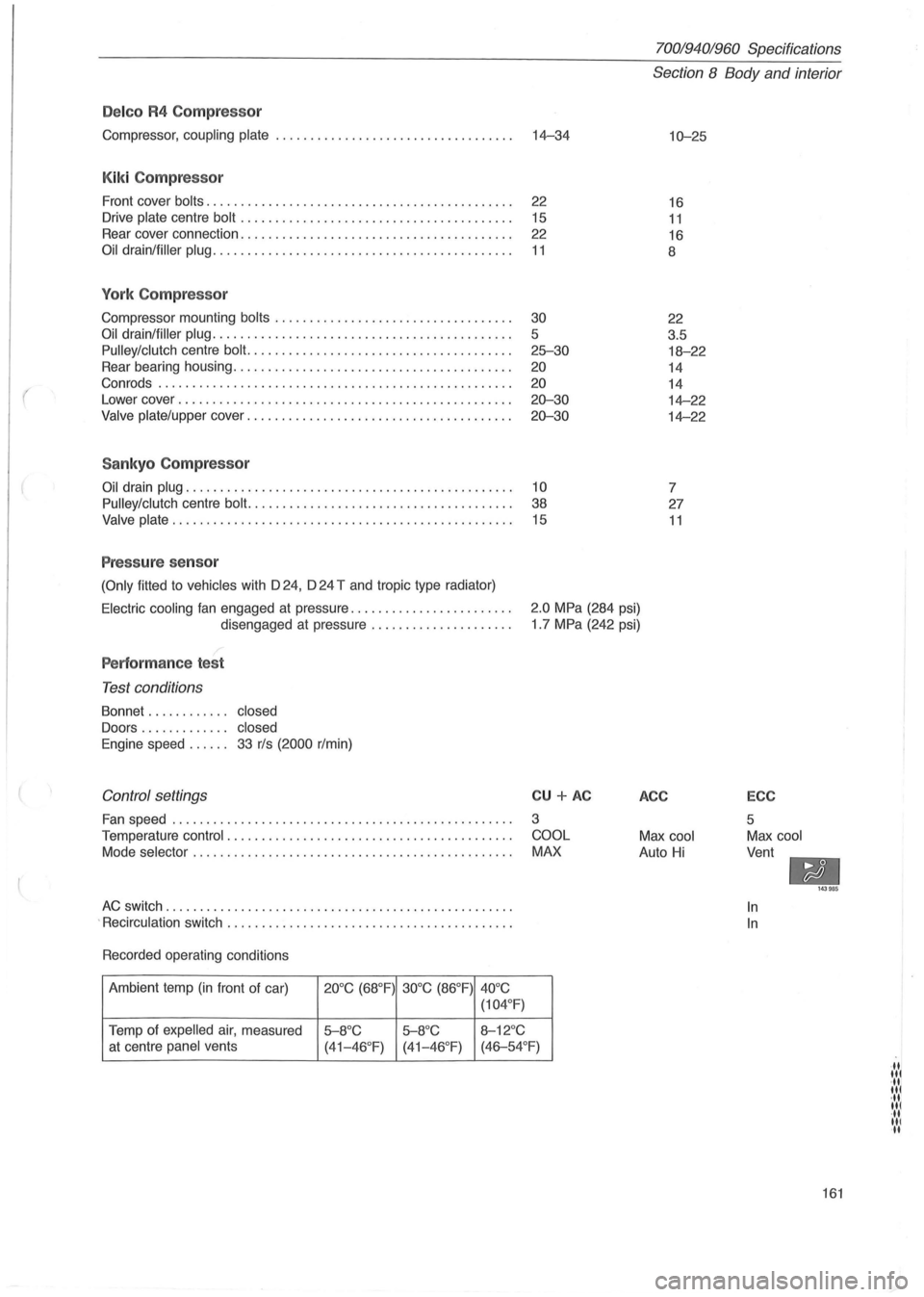
(
Delco R4 Compressor
Compressor, coupling plate ................................... 14-34
Kiki Compressor
Front cover bolts. . . . . . . . . . . . . . . . . . . . . . . . . . . . . . . . . . . . . . . . . . . . . 22
Drive
plate centre bolt . . . . . . . . . . . . . . . . . . . . . . . . . . . . . . . . . . . . . . . . 15
Rear cover connection. . . . . . . . . . . . . . . . . . . . . . . . . . . . . . . . . . . . . . . .
22
Oil drain/filler plug. . . . . . . . . . . . . . . . . . . . . . . . . . . . . . . . . . . . . . . . . . . . 11
York Compressor
Compressor mounting bolts ........................ .......... .
Oil drain/filler plug ........................................... .
Pulley/clutch centre bolt. ..................................... .
Rear bearing housing
.................................. ...... .
Con rods .
.................................................. .
Lower cover
........................................ .. ...... .
Valve plate/upper cover ...................................... .
Sankyo Compressor
30
5
25-30
20
20
20-30
20-30
Oil drain plug. . . . . . . . . . . . . . . . . . . . . . . . . . . . . . . . . . . . . . . . . . . . . . . . 10
Pulley/clutch
centre bolt. . . . . . . . . . . . . . . . . . . . . . . . . . . . . . . . . . . . . . . 38
Valve plate. . . . . . . . . . . . . . . . . . . . . . . . . . . . . . . . . . . . . . . . . . . . . . . . . . 15
Pressure sensor
(Only fitted to vehicles with D 24, D 24 T and tropic type radiator)
70019401960 Specifications
Section 8 Body and interior
10-25
16
11
16
8
22
3.5
18-22
14
14
14-22
14-22
7
27
11
Electric cooling fan engaged at pressure ....................... .
disengaged at pressure
.................... .
2.0 MPa (284 psi)
1 .7 MPa (242 psi)
Performance test
Test conditions
Bonnet . . . . . . . . . . .. closed
Doors . . . . . . . . . . . .. closed
Engine
speed. . . . .. 33 r/s (2000 r/min)
Control settings
Fan speed ........................... ...................... .
Temperature
control . ................................. ....... .
Mode
selector . ............................................. .
AC switch ............. ..................................... .
.
Recirculation switch ......................................... .
Recorded operating conditions
Ambient temp
(in front of car) 20°C (68°F) 30°C (86°F)
40°C
(104 °
F)
Temp of expelled air, measured 5-8°C 5-8°C 8-12°C
CU + AC
3
COOL
MAX
at centre panel vents
(41-46°F) (41-46 °F) (46-54°F)
ACC
Max cool
Auto Hi
ECC
5
Max cool
Vent
-In
In
143985
161
·11 lit ·11 lit ·11 lit ·11 III II