weight VOLVO 960 1982 Service Repair Manual
[x] Cancel search | Manufacturer: VOLVO, Model Year: 1982, Model line: 960, Model: VOLVO 960 1982Pages: 168, PDF Size: 54.28 MB
Page 7 of 168
(
70019401960 Specifications
Section
0 General
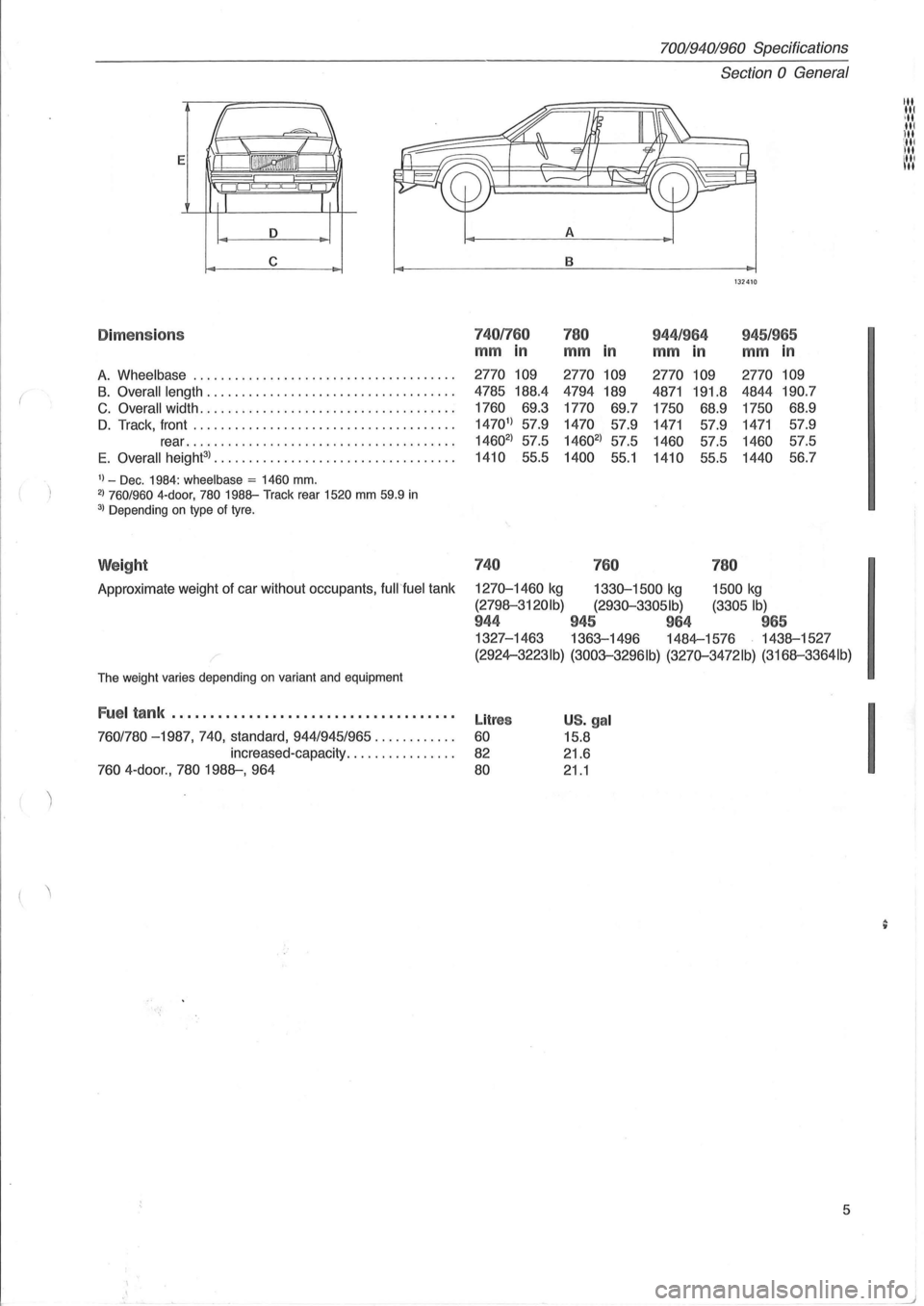
E
A
c B
132410
Dime ns io n s 7401760 780 944 /964 945/965
mm in mm in mm in mm in
A. Wheelbase .............................. . ...... . 2770 109 2770 109 2770
109 2770 109
B. Overall
length ................................... . 4785 188.4 4794
189 4871 191.8 4844 190.7
C. Overall width .................................... .
1760
69.3
1770 69.7
1750 68.9 1750 68.9
D. Track,
front ..................................... . 14701
) 57.9 1470 57.9 1471 57.9 1471 57.9
rear
................. ..................... . 14602
) 57.5 14602
) 57.5 1460 57.5 1460 57.5
E
. Overall height3
) ...... .........................•.•. 1410 55.5 1400 55.1 1410 55.5 1440 56.7
1) _ Dec. 1984: wheelbase = 1460 mm. 2) 760/960 4-door, 780 1988-Track
rear 1520 mm 59.9 in 3) Depending on type of tyre.
Weight 740
760 780
Approximate weight of car without occupants, fuWfuel tank 1270-1460 kg 1330-1500 kg 1500 kg
(2798-3120Ib) (2930-33051b) (3305 Ib)
944 945 964 965
1327-1463 1363-1496 1484-1576 1438-1527
,-(2924-3223Ib) (3003-3296Ib) (3270-3472lb) (3168-3364Ib)
The weight varies depending on variant and equipment
Fuel tank .................................... .
760/780 -1987,740, standard, 944/945/965 ........... .
increased-capacity
............... .
760 4 -door ., 780 1988-, 964
Litres
60
82
80
US. gal
15.8
21.6
21.1
5
I
Page 10 of 168
70019401960 Specifications
Section 0 General
Product plate
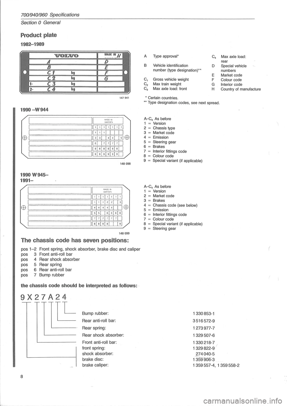
1982-1 989
A Type approval *
B Vehicle identification
number (type designation) **
C
1 Gross vehicle weight
C
2 Max train weight Ca Max axle load: front C
4 Max axle
load: rear
D Special vehicle
numbers
E Market code
F
Colour code
G Interior code
H Country of manufacture
147941 * Certain countries.
199 0 -W 944
II '. 1.'DE Irl ~========:~===;:=:::;::;W::::,::::EW'::;:::::=r== ;==============ill, , , ,I, ,1'1 II' , , I I EEl ~===========;II 3 3 + El EEl
;==============ill 6 7 71 7 7 1 I II a a a al a al I ~===================; 11999919911
1 99 0 W 945-
199 1-
[ '.11'10E III S I.'/ FD E"I
148098
,I, ,1,1,1,1,1
EEl ~I ======== I
,I, ,I 21 21 I 31
41441414 1 I IEEl
515 161616161
71 7 7 1 71 71 71 I
Iiaia alai I 191
14 8099
The chass is code~has seven positions :
pos 1-2 Front spring, shock absorber, brake disc and caliper
pas 3 Front anti -roll bar
pas 4 Rear shock absorber
pas 5 Rear spring
pas 6 Rear anti -roll bar
pas 7 Bump rubber
the ch ass is code sh ould be inte rp reted as follow s: ~
9X27A24
E
8
Bump rubber:
Rear
anti -roll bar:
Rear spring:
Rear shock absorber:
Front
anti -roll bar:
front spring:
shock absorber:
brake disc:
brake
caliper:
** T ype designation codes, see next spread.
A-C4 As before
1 = Version
2 = Chassis type
3 = Market code
4 = Emission
5 = Steering gear
6 = Brakes
7 = Interior fittings code
8 = Colour code
9 = Special variant (if applicable)
A-C4 As before
1 = Version
2 = Market code
3 = Brakes
4
= Chassis code (see below) 5 = Emission
6 = Interior fittings code
7 = Colour code
8 = Special variant (if applicable) 9 = Steering gear
1330853 -1
3516572 -9
1273977-7
1329507 -6
1330218 -7
1329822-9 I
2 74040 -5
1359906 -3
1359557-4, 1359558- 2
(
Page 17 of 168
70019401960 Specifications
Section 2 B 19, B 23 Engines
Section 2 B 19, B 23 Engines
Group 20 General ................................ 15
Group
21 Engine assembly ........................ 16
Group 22 Lubricating system
....................... 20
Group 23 Fuel system ............................ 21
Group 25 Intake and exhaust systems .............. 31
Group 26 Cooling system .......................... 32
Group 28
Ignition system .......................... 33
j'"
I.t
Group 20 General ~ :,
129750
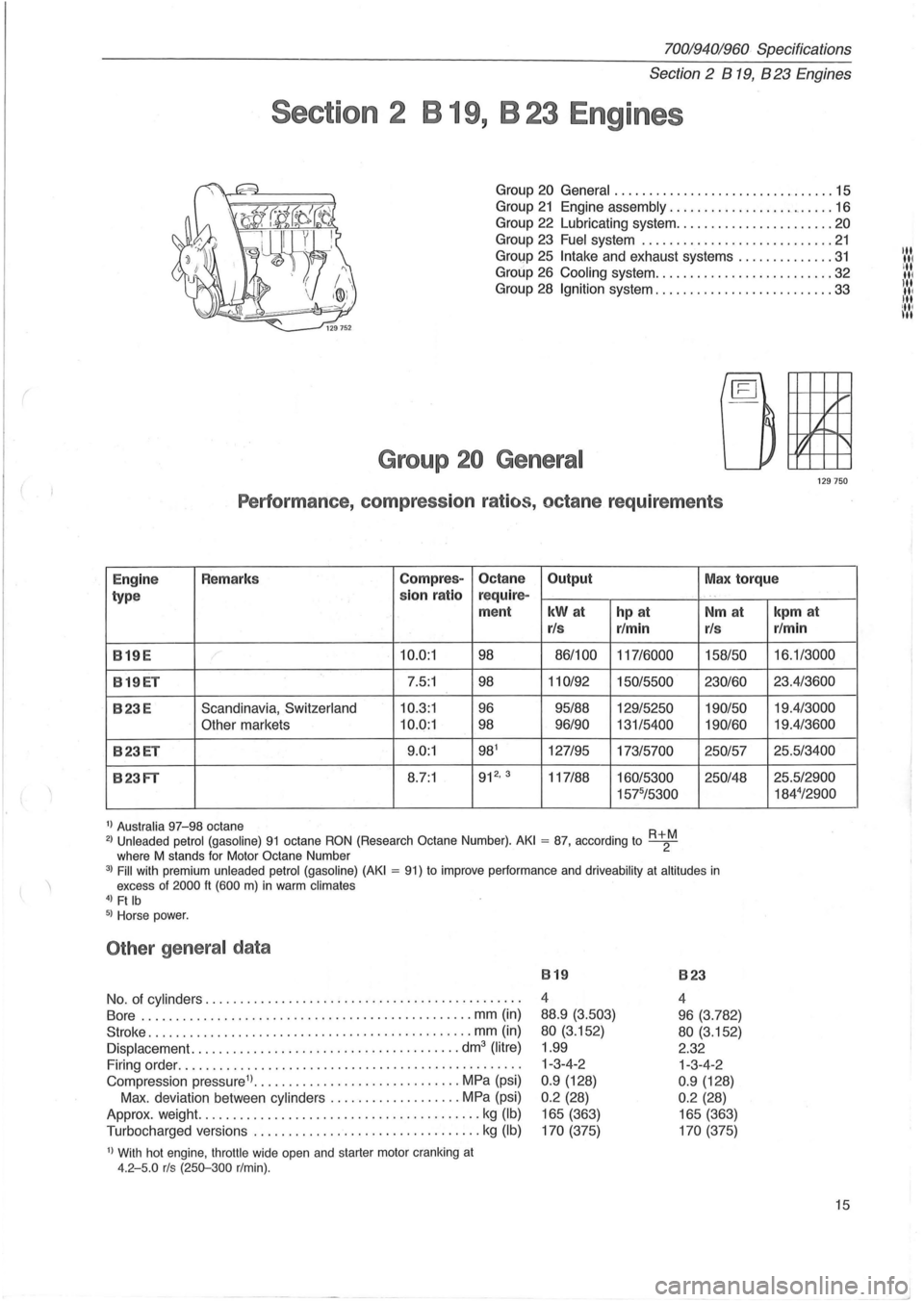
Performance , compression ratios, octane requirements
Engine Remarks Compres-Octane
Output Max torque
type sion
ratio r
equire-
ment
kWat hp at
r/s r/min
819E 10.0:1 98 86/100
117/6000
819ET 7.5:1 98 110/92
150/5500
823E Scandinavia, Switzerland 10.3:1 96 95/88 129/5250
Other markets 10.0:1 98 96/90 131/5400
823ET 9.0:1 981 127/95 173/5700
823FT 8.7:1 912
• 3 117/88 160/5300
1575/5300
1) Australia 97-98 octane 2) Unleaded
petrol (gasoline) 91 octane RON (Research Octane Number). AKI = 87, according to R+2M where M stands for Motor Octane Number
. "
Nm at
r/s
158/50
230/60 190/50
190/60
250/57
250148
3) Fill with premium unleaded petrol (gasoline) (AKI = 91) to improve performance and driveability at altitudes in excess of 2000 It (600 m) in warm climates 4) Ft Ib 5) Horse power.
Other general data
No. of cylinders ............................................. .
Bore .
............................................. .. mm (in)
Stroke ..
.... ......................................... mm (in)
Displacement. ...................................... dm3 (litre)
Firing order ................................................. .
Compression pressure1) ..
............................ MPa (psi)
Max . deviation between
cylinders ................... MPa (psi)
Approx. weight.
............... ........... ..... ......... kg (Ib)
Turbocharged versions ................................. kg (Ib)
1) With hot engine, throttle wide open and starter motor cranking at 4.2-5.0 rls (250-300 r/min).
819
4
88.9
(3.503)
80 (3.152)
1.99
1-3-4-2
0.9 (128)
0 .2 (28)
165 (363)
170 (375)
823
4
96 (3.782)
80 (3.152)
2.32 1-3-4-2
0 .9 (128)
0 .2 (28)
165 (363)
170 (375)
kpm at
r/min
16.1/3000
23.4/3600
19.4/3000
19.4/3600
25.5/3400
25.5/2900 184
4/2900
15
Page 18 of 168
70019401960 Specifications
Section 2 B 19, 823 Engines
Group 21 Engine block
Cylinder head
Height, new ................................... mm (in) 146.1 (5.756)
min (after machining)
.................... mm (in) 145.6 (5.737)
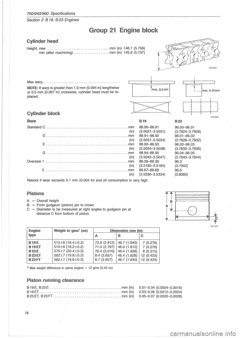
Max warp ..
.. ..................................... . .
NOTE: If warp is greater than 1 .0 mm (0.094 in) lengthwise
or 0 .5 mm (0.097 in) crosswise, cylinder head must be re
placed.
Cylinder block
Bore 819 823
Standard C ............................................ .. mm
(in)
D .............................................. mm (in)
E .............................................. mm
(in)
G ........................................... . .. mm
(in)
Oversize 1
...................................... .... .... mm
(in)
2 ..... . -:-......................... ....... ....... mm
(in) 88.9D-88
.
91
(3.5027-3 .5031 )
88 .
91-88.92
(3.5031-3.5034)
88.92 -88.93
(3.5034-3.5038)
88.94-88.95
(3.5042-3.5047)
89 .29-89.30
(3.518D-3 .5184)
89.67-89.68
(3. 533D-3 .5334)
96 .0D-96.01
(3.7824-3. 7828)
96 .01-96.02
(3.7828-3.7832)
96 .02-96.03
(3.7832-3.7836)
96 .04-96.05
(3.7 84D-3 .7844)
96.3
(3.7 942)
96 .6
(3.8060)
Rebore if wear exceeds 0.1 mm (0.004 in) and oil consumption is very high.
Pistons
A = Overall height
8
= From gudgeon (piston) pin to crown
C = Diameter to be measured at right angles to gudgeon pin at
distance
C from bottom of piston.
Engine Weight in gms1 (oz) Dimension mm (in)
type A 8
8 19 E
515±6 (18.4±0.2)
73.9 (2.912) 46.7 (1.840)
8 19
ET 510±6 (18.2±0.2) 71.0 (2.797) 46.0 (1.812)
823E 570±7 (20.4±0.3) 76.4 (3.010) 46.4 (1.828)
823ET 562±7 (19.8 ±0.3) 8.4 (2.657)
46.4 (1.828)
823FT 562±7 (19.8±0.3) 8.7 (2.657)
46.7 (1.840)
1) Max weight difference in same engine = 12 gms (0.43 oz)
Piston running clearance
819 E, 823 E ........................................ mm (in)
819ET .............................................. mm (in)
823 ET, 823 FT ...................................... mm (in)
16
C
7 (0.276)
7 (0.276)
8 (0.315)
12 (0.423)
12 (0.423)
0.01- 0 .04 (0.0004-0.0016)
0 .03- 0.06 (0.0012-0 .0024)
0 .05-0.07 (0.002D-0 .0028)
J
ma x o 25mm
129826
137551
Page 21 of 168
(
70019401960 Specifications
Section 2 B 19, B 23 Engines
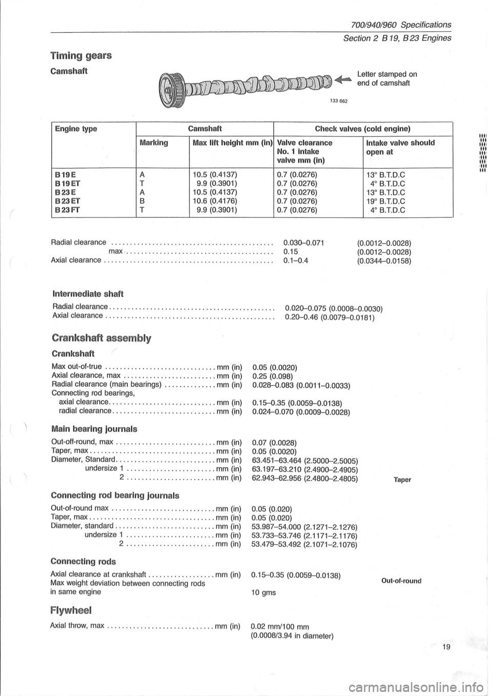
Timin g gears
Camshaft Letter stamped on
end ot camshaft
Engine type Camshaft
Check valves (cold engine)
Marking Max
lift height mm (in) Valve clearance
No.1 intake
valve mm (in)
B
19E A 10.5 (0.4137) 0.7 (0.0276)
B19ET T 9.9 (0.3901)
0.7 (0.0276)
B23E A 10.5 (0.4137) 0.7 (0.0276)
B23ET B 10.6 (0.4176) 0.7 (0.0276)
B23FT T 9.9 (0.3901)
0.7 (0.0276)
Radial clearance
............................................ 0.030-0 .071
max... . .... ... ............................... 0.15
Axial clearance . . . . . . . . . . . . . . . . . . . . . . . . . . . . . . . . . . . . . . . . . . . . . . 0.1-0.4
Int ermed iate shaft
Intake valve should
open at
13° B.T.D.C
4° B.T.D.C
13° B.TD.C
19° B.TD.C
4° B.iD.C
(0.0012-0 .0028)
(0.0012-0.0028)
(0.0344-0.0158)
Radial clearance.
. . . . . . . . . . . . . . . . . . . . . . . . . . . . . . . . . . . . . . . . . . . . 0.020-0.075 (0.0008-0.0030)
Axial clearance .
. . . . . . . . . . . . . . . . . . . . . . . . . . . . . . . . . . . . . . . . . . . . . 0.20-0.46 (0.0079-0.0181)
Crankshaft assembly
Crankshaft
Max out-ot-true .............................. mm (in)
Axial clearance, max ......................... mm (in)
Radial clearance (main bearings) .............. mm (in)
Connecting
rod bearings,
axial clearance ............................. mm (in)
radial clearance ............................ mm (in)
Main bearing journals
Out-oft-round, max ........................... mm (in)
Taper, max
.................................. mm (in)
Diameter, Standard .
.......................... mm (in)
undersize 1
........................ mm (in)
2 .
................ ....... mm (in)
Connecting rod bear ing journ als
Out-ot- round max ............................ mm (in)
Taper, max
.................................. mm (in)
Diameter, standard
........................... mm (in)
undersize 1
........................ mm (in)
2 ........................ mm (in)
Connecting rods
0.05 (0.0020)
0.25 (0.098)
0 :028-0.083 (0.0011-0.0033)
0.15-0.35 (0.0059-0.0138)
0 .024-0.070 (0.0009-0.0028)
0.07 (0.0028)
0.05 (0.0020)
63.451-63.464 (2.5000-2.5005)
63.197-63.210 (2.4900-2.4905)
62.943-62.956 (2.4800-2.4805)
0.05 (0.020)
0.05 (0.020)
53.987-54.000
(2.1271-2.1276)
53.733-53.746 (2.1171-2.1176)
53.479-53.492
(2.1071-2.1076)
Axial clearance
at crankshaft .................. mm (in) 0.15-0.35 (0.0059-0.0138)
Max weight deviation between connecting rods
in same engine 10 gms
Flywheel
Axial throw, max ............................. mm (in) 0.02 mm/100 mm
(0.0008/3.94 in diameter)
Taper
Out-of-round
19
1111 :111
111/ III III '
, III
III '
·111 III
"1
I
~J
Page 38 of 168
70019401960 Specifications
Section 2 B 200, B 230 Engines
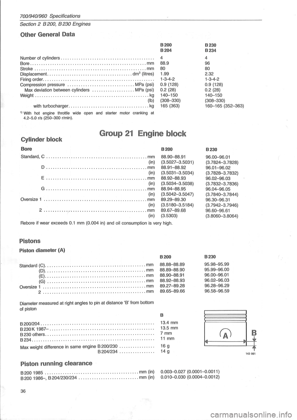
Other General Data
Number of cylinders ......................................... .
80re .................................................... mm
Stroke .................................................. mm
Displacement. ..................................... dm3 (litres)
Firing order ................................................. .
Compression pressure
.............................. MPa (psi)
Max deviation between
cylinders ................... MPa (psi)
Weight
.................... ..................... .......... kg
(Ib)
B200
B204
4 88.9
80
B230
B234
4
96
80
2.32 1-3-4-2
0.9 (128)
0.2 (28)
140-150
(308-330)
with turbocharger .................................... kg
1.99
1-3-4-2
0.9 (128)
0.2 (28)
140-150
(308-330)
165 (363) 160-165 (352-363)
1) With hot engine throttle wide open and starter motor cranking at 4.2-5.0 rls (250-300 r/min).
Cylinder block
Bore
Group 21 Engine block
Standard, C ............................................. mm
(in)
o .... ............ ..................... ........ mm
(in)
E
.... ......................................... mm
(in)
G .
............................................ mm
(in)
Oversize
1 .......... . ........... ........................ mm
(in)
2 ............ -.................................. mm
(in)
B200
88.90-88.91
(3.5027-3.5031 )
88.91-88.92
(3.5031-3.5034)
88.92-88.93
(3.5034-3 .5038)
88.94-88.95
(3.5042-3.5047)
89.29-89.30
(3.5180-3.5184)
89 .
67-89.68
(3.5303)
Rebore if wear exceeds 0.1 mm (0.004 in) and oil consumption is very high.
Pistons
Piston diamete r (A)
Standard (C) ............................................. mm
(D) ............................................. mm
(E)
....................................... ...... mm
(G) ........ .................................... mm
Oversize 1 .............................................. mm
2 ................................ ······· ·······mm
Diameter measured at right angles to pin at distance 'B' from bottom
of piston
B200
88.88-88.89
88.89-88.90
88.90-88.91
88.92-88.93
89.27-89.28
89.65--89 .66
B
8200/204 . . . . . . . . . . . . . . . . . . . . . . . . . . . . . . . . . . . . . . . . . . . . . . . . . . . 13.4 mm
B230K 1987-..... ...... ................. ................... 13 .5 mm
8230 others. . . . . . . . . . . . . . . . . . . . . . . . . . . . . . . . . . . . . . . . . . . . . . . . . 7 mm
8234....................................................... 11 mm
Max weight difference in same engine 8200/230 . . . . . . . . . . . . . . . . 16 g 8204/234 ................ 14 g
P iston running clearance
B230
96.00-96.01
(3.7824-3.7828)
96.01-96.02
(3.7828-3.7832)
96.02-96.03
(3.7832-3.7836)
96.04-96.05
(3.7840-3.7844)
96.30-96.31 (3.7942-3.7946)
96.60-96.61
(3.8060-3.8064)
B230
95.98-95.99
95.99-96.00
96.00-96.01 96.02-96.03
96.28-96.29
96.58-96.59
(fJ .... .,
8200 1985 .......................................... mm (in)
8200 1986--, B 204/230/234 ..... ...................... mm (in)
0.003-0.027 (0.0001-0.0011)
0.010-0.030 (0.0004-0.0012)
36
... -,.
B
~r
~~
143981
Page 43 of 168
(
70019401960 Specifications
Section
2 B 200, B 230 Engines
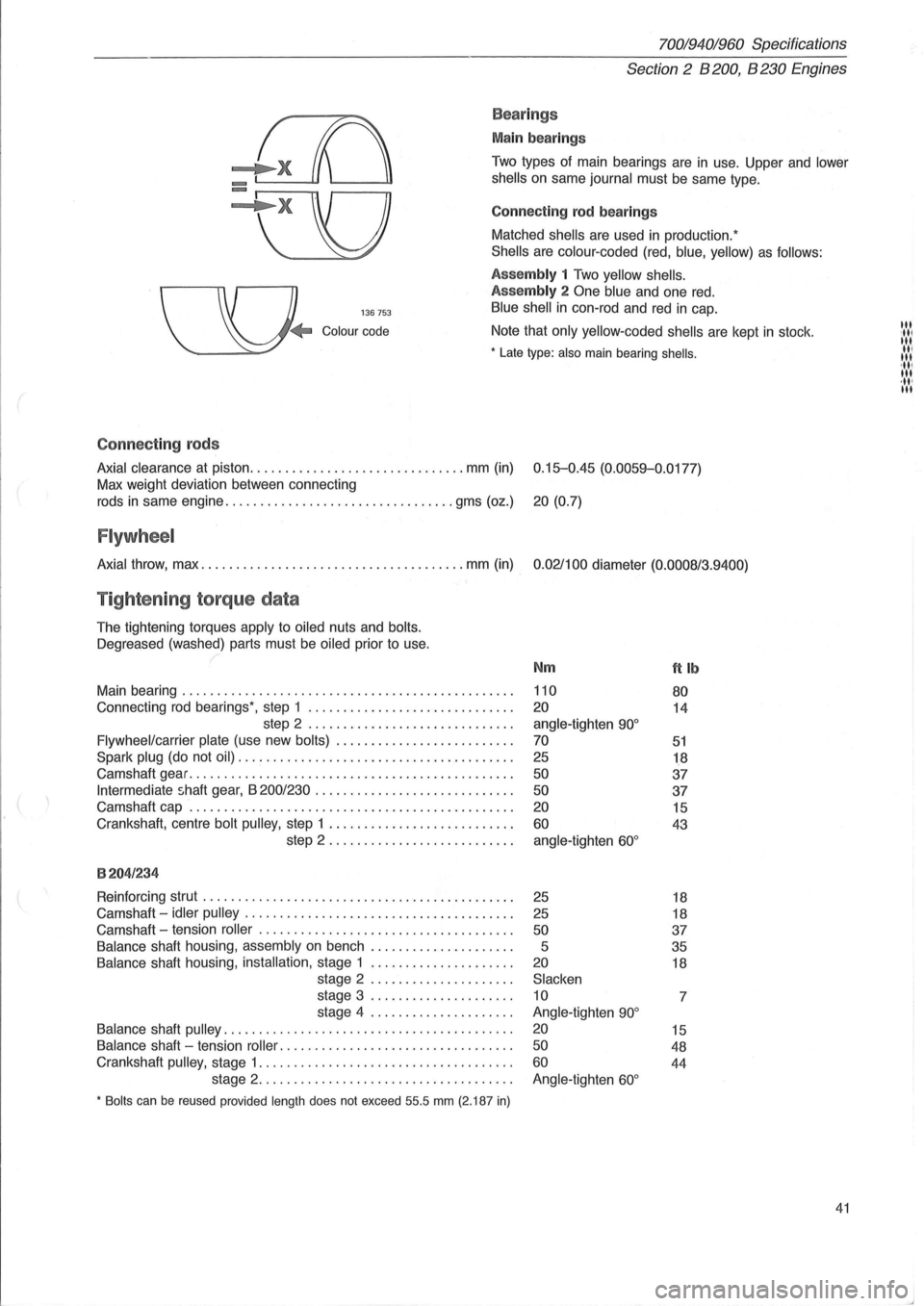
Bea rings
Main bearings
Two types of main bearings are in use. Upper and lower
shells
on same journal must be same type.
Connect
ing rod bearings
Matched
shells are used in production:
Shells are colour -coded (red, blue, yellow) as follows:
136753
Assembly 1 Two yellow shells.
Assembly
2 One blue and one red.
Blue shell in con-rod and red in cap.
Colour code Note that only yellow-coded shells are kept in stock .
• Late type: also main bearing shells .
Connect ing rods
Axial clearance at piston ............................... mm (in) 0.15-0.45 (0.0059-0.0177)
Max weight deviation between connecting
rods
in same engine ................................. gms (oz.) 20 (0.7)
Flywheel
Axial throw, max ...................................... mm (in) 0.021100 diameter (0.0008/3.9400)
Tightening torque data
The tightening torques apply to oiled nuts and bolts.
Oegreased
(washed) parts must be oiled prior to use.
Main bearing
............................................... .
Connecting
rod bearings', step 1 ............................. .
step 2
............................. .
Flywheel/carrier plate (use new bolts) ...................... ... .
Spark plug (do not oil) ....................................... .
Camshaft gear
.............................................. .
Intermediate shaft gear, B 200/230 ............................ .
Camshaft cap
.............................................. .
Crankshaft, centre
bolt pulley, step 1 .......................... .
step 2 .
.. ....................... .
8204/234
Reinforcing strut ............................................ .
Camshaft -
idler pulley ...................................... .
Camshaft -tension
roller .................................... .
Balance shaft housing, assembly on bench .................... .
Balance shaft housing, installation, stage 1 .................... .
stage 2
.................... .
stage 3
.................... .
stage 4
.................... .
Balance shaft pulley ......................................... .
Balance shaft -tension roller .. ............................... .
Crankshaft
pulley, stage 1 .................................... .
stage 2
.................................... .
• Bolts can be reused provided length does not exceed 55.5 mm (2.187 in)
Nm
110
20
angle-tighten 90°
70
25
50
50
20
60
angle-tighten 60°
25
25
50
5
20
Slacken
10
Angle-tighten
90°
20
50
60
Angle-tighten 60°
ftlb
80
14
51
18
37
37
15
43
18
18
37
35
18
7
15
48
44
41
III :11' III II, III 'III III ,11' III
Page 71 of 168
70019401960 Specifications
Section
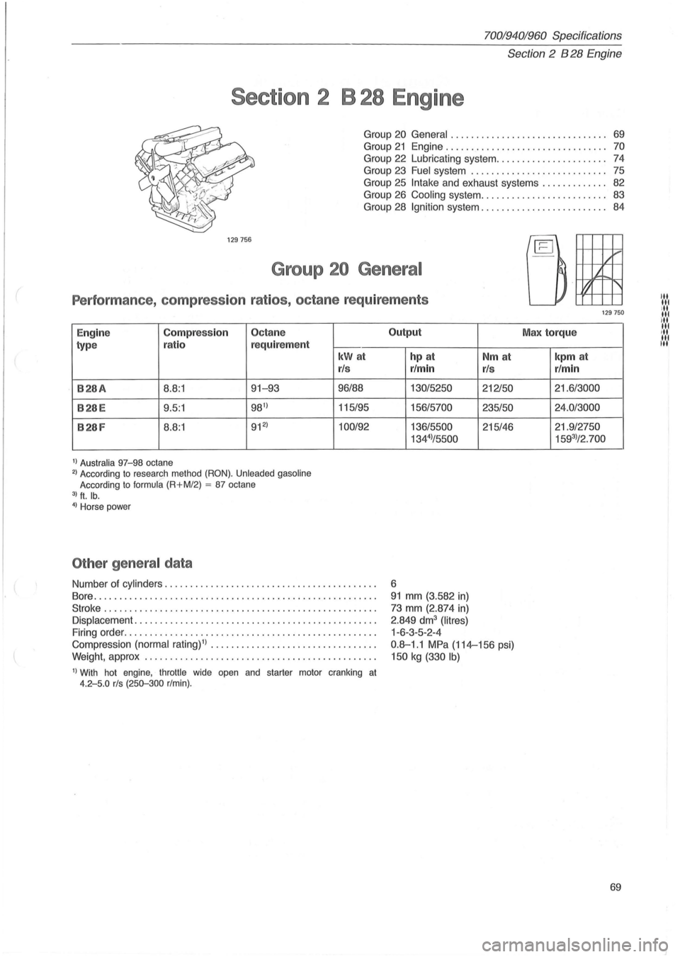
2 B 28 Engine
Section 2 B 28 Engine
Group 20 General . . . . . . . . . . . . . . . . . . . . . . . . . . . . . .. 69
Group 21 Engine................................ 70
Group 22 Lubricating system ...................... 74
Group 23 Fuel system ............ . . . . . . . . . . . . . .. 75
Group 25
Intake and exhaust systems ............. 82
Group 26 Cooling system ......................... 83
Group 28
Ignition system. . . . . . . . . . . . . . . . . . . . . . . .. 84
129756
Group 20 General
Performance, compression ratios, octane requirements
E ngine Compression Octane
type ratio r
eq
uirement
B28A 8.8:1 91-93
B28E 9 .5 :1 981
)
B28F 8.8 :1 912
)
1) Australia 97-98 octane 2) According to research method (RON). Unleaded gasoline
According to formula (R+M/2) = 87 octane 3) ft. lb. 4) Horse power
Other general data
kWat
rl s
96/88
115/95
100/92
Number of cylinders ......................................... .
Bore
.............. ......................................... .
Stroke ................ " ................................... .
Displacement ............................................... .
Firing order
................................................. .
Compression
(normal rating)l) ........................... ..... .
Weight, approx
................ ............................. .
I) With hot engine, throttle wide open and starter motor cranking at 4.2-5.0 rls (250-300 r/min).
Output
hp at
r/min
130/5250
156/5700
136/5500
134
4)/5500
6
91 mm (3.582 in)
73 mm (2.874 in)
2 .849 dm3 (Iitres)
1-6-3-5 -2-4
Nm at
rl s
212150
235/50
215/46
0.8-1 .1 MPa (114-156 psi)
150 kg (330 Ib)
/ ......
l.t
~ '
129750
Max torque
kpm at
r/min
21.6/3000
24.0/3000
21. 9/2750
1593)/2. 700
69
"' '" ill
,' ....
N,'
'" III
Page 72 of 168
70019401960 Specifications
Section'-2" B 28 Engine
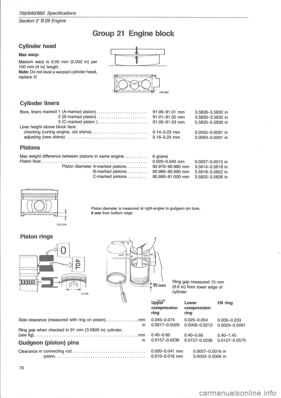
Group 21 Engine block
Cylinder head
Max warp:
Maxium warp is
0.05 mm (0.002 in) per
100 mm (4 in) length.
Note: Do not level a warped cylinder head,
replace it!
Cylinder liners
[
Bore, liners marked 1 (A-marked piston) ....................... .
2 (B-marked piston) ....................... .
3 (C-marked piston) ...................... .
Liner height above
block face:
checking (runing engine,
old shims) ....................... .. .
adjusting (new shims)
..................................... .
Pistons
Max weight difference between pistons in same engine .......... .
Piston
float ................................................. .
Piston diameter A-marked pistons
......... .
B-marked pistons
......... .
C-marked pistons
........ .
]
91.00-91.01 mm
91.01-91.02 mm
91.02-91.03 mm
0.14--0.23 mm
0.16-0.23 mm
6 grams
0.020-0.040 mm
90.970-90.980 mm
90.980-90.990 mm
90.990-91.000 mm
3.5826-3.5830 in
3.5830-3.5835 in
5.5835-5.5838 in
0.0055-0.0091 in
0.0063-0.0091 in
0.0007-0. 0015 in
3.5814-:3.5818 in
3.5818-3.5822 in
3.5822-3.5826 in
((0)) t
'" ~L-f
Piston diameter is measured at right-angles to gudgeon pin bore, S mm from bottom edge.
135676
Piston rings
/,
I 111111111 ~III
'--J 115085
Side clearance (measured with ring on piston) ............... mm
in
Ring gap when checked in 91 mm (3.5826 in) cylinder,
Ring gap measured 15 mm
(0.6 in) from lower edge of
cylinder
U 129520 pper
compression
ring
0.045-0.074
0.0017-0.0029
Lower Oil ring
compression
ring
0.025-0.054 0.009--0.233
0.0009--0.0212 0.0003-0.0091
(see fig) ................................................. mm 0.40-0.60 0.40-0.60 0.40-1.45
in 0.0157-0.0236 0.0157-0.0236 0.0157-0.0570 Gudgeon (piston) pins
Clearance in connecting rod. . . . . . . . . . . . . . . . . . . . . . . . . . . . . . . . . . . 0.020-0.041 mm
piston. . . . . . . . . . . . . . . . . . . . . . . . . . . . . . . . . . . . . . . . . . .
0.010-0.016 mm
70 0.0007-0.0016
in
0.0003-0.0006 in
Page 75 of 168
{
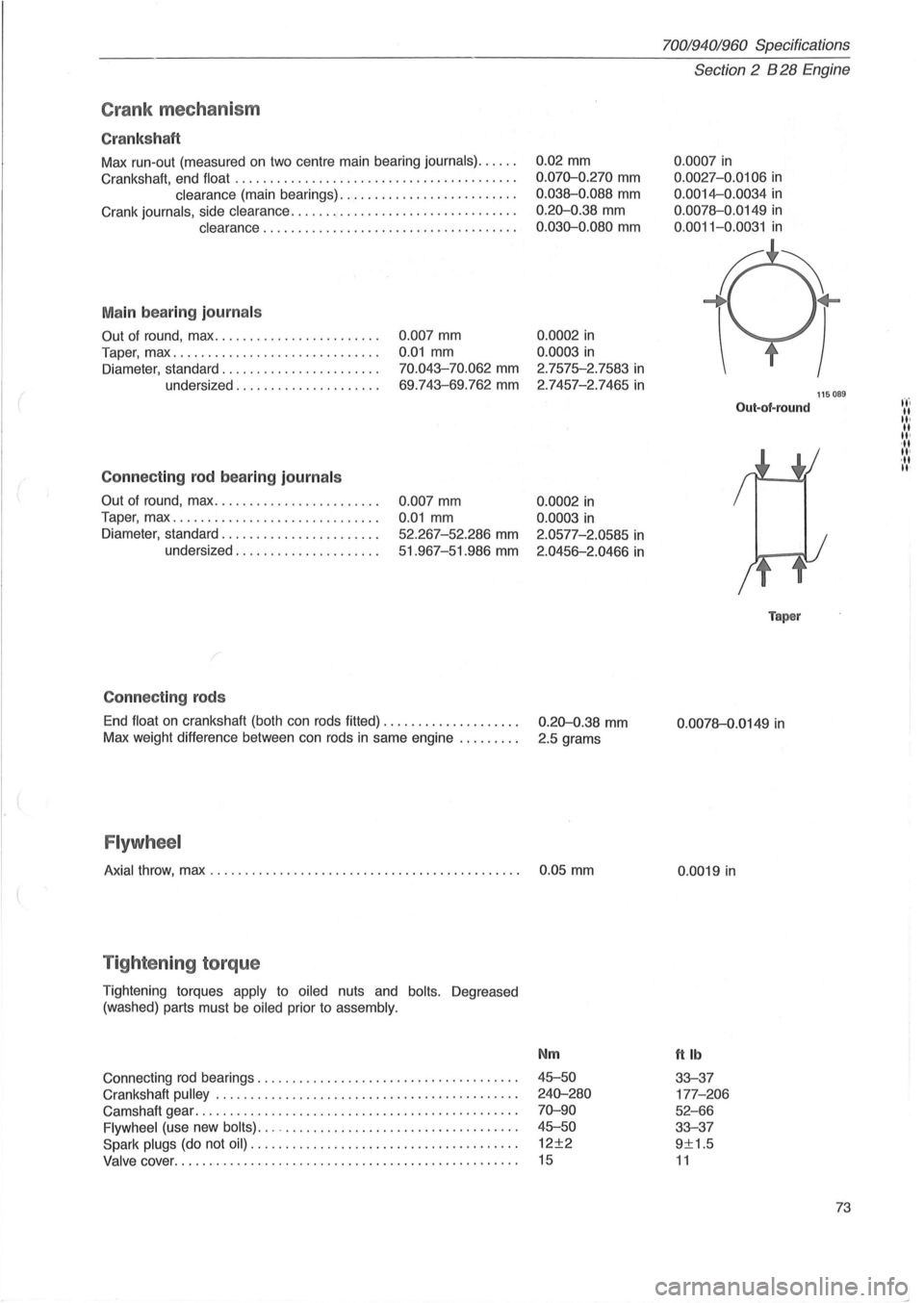
Crank mec ha ni sm
Cr ank sh aft
Max run-out (measured on two centre main bearing journals) ..... .
Crankshaft, end float
........................................ .
clearance (main bearings) ......................... .
Crank
journals, side clearance ...........•.................... .
clearance .................................... .
M ain bea rin g journ als
Out of round, max ....................... .
Taper, max
...... ....................... .
Diameter, standard ...
................... .
undersized
.................... .
Conne cting rod b ea ring journ als
Out of round, max ....................... .
Taper, max
............................. .
Diameter, standard
...................... .
undersized
.................... .
C onnec tin g rods
0 .007 mm
0.01 mm
70.043-70.062 mm
69 .743-69.762 mm
0.007 mm
0.01 mm
52.267-52 .286 mm
51.967-51.986 mm
End
float on crankshaft (both can rods fitted) ................... .
Max weight difference between can rods
in same engine ........ .
Flywh eel
0.02 mm
0 .070-0.270 mm
0.038-0.088 mm
0.20-0.38 mm
0 .030-0.080 mm
0.0002 in
0.0003 in
2.7575-2.7583 in
2 .7457-2.7465 in
0.0002 in
0.0003 in
2.0577-2.0585 in
2.0456-2.0466 in
0.20-0.38 mm
2.5 grams
Axial throw, max . . . . . . . . . . . . . . . . . . . . . . . . . . . . . . . . . . . . . . . . . . . . . 0 .05 mm
T ig hte nin g torq ue
Tightening torques apply to oiled nuts and bolts. Degreased
(washed) parts must be
oiled prior to assembly.
Connecting rod bearings ................. .......... ..... ..... .
Crankshaft
pulley . ........ .......... ........................ .
Camshaft gear
................................. ............. .
Flywheel (use new bolts) ... -................................. .
Spark plugs (do not oil) ...................................... .
Valve cover ......... .................................... .... .
Nm
45-50
240-280
70-90
45-50
12±2
15
70019401960 Specifications
Section 2 B 28 Engine
0 .0007 in
0.0027 -0.0106 in
0.0014-0.0034 in
0.0078-0 .0149 in
0 .0011-0.0031 in
Out-of-round
Taper
0 .0078-0.0149 in
0.0019 in
ttlb
33-37
177 -206
52-66
33-37
9±1.5
11
115089
73
t't'. -II II· II II' ,II II'
,II II'