wheel VOLVO 960 1982 Service Repair Manual
[x] Cancel search | Manufacturer: VOLVO, Model Year: 1982, Model line: 960, Model: VOLVO 960 1982Pages: 168, PDF Size: 54.28 MB
Page 3 of 168
(
)
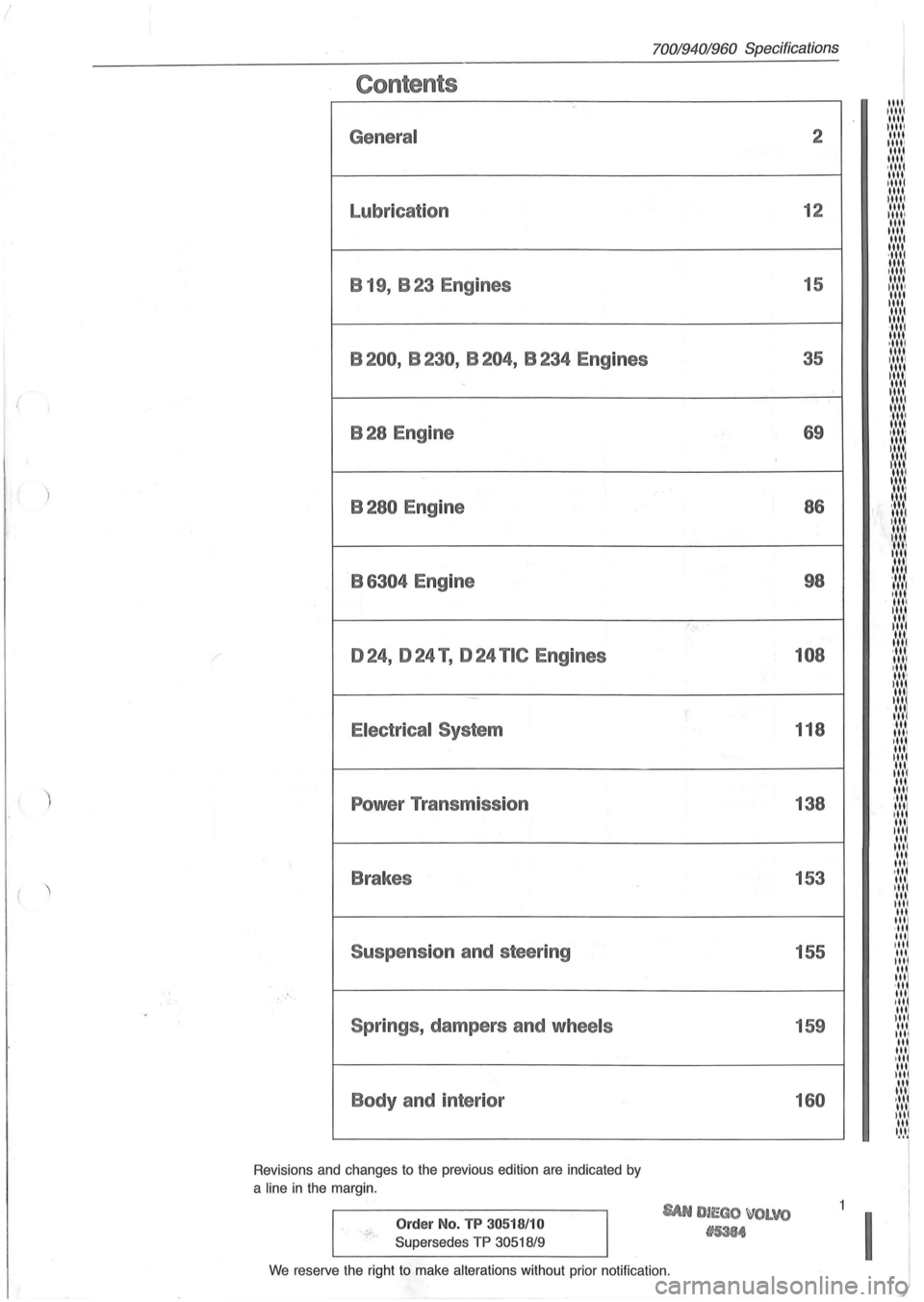
Contents
General
Lubrication B 19, B 23 Engines
B200, B230, B204, B234 Engines
B28 Engine
B280 Engine
B
6304 Engine
024, 024 T , 024 TIC Engines
Electrical System
Power Transmission
Brakes
Suspension and steering
Springs , dampers and
wheels
Body and interior
Revisions and changes to the previous edition are indicated by
a
line in the margin.
Order No. TP 30518/10
Supersedes TP 30518/9
70019401960 Specifications
'., ..
SAN DIEGO ~OLVO
tI5384
2
12
15
35
69 86
98
108
118
138
153 155
159
160
We reserve the right to make alterations without prior notification.
11111 1 1111 1111 IIII! 1111
11111 1111 1111 ·1111 1111 11111 1111 11111 1111 11111 1111 1111 1111
;::::::: 1111 1,1 ..... 1111 II,' ....
~:,:,:,: 1111 , ...... 1
1,' .... 1
1 ...... 1 1111 ·11" 1111 ,II', 1111 III'
I:':':':
'"' '"' ~ .... ,'. 1111 , .... " 1 III' 1111
:I:':',~ ·11 11,1
,"' 1111 III'
'" 1111 ...... 1 ,11' "'1 ,II'
"" I .... I~ III
"' "' ·111 1111 ,III
"' I II I
'" 1111
"' 1111
·11' 1111 I II 1 III III 11 .... 1 III 111/ ,II til. '"I III 1111 .'.'111 ,III 111/ ,II
11.'.'1
Itt'.'1
' llt
lit 'II It.'I'1 It.'.'1 III IItl 'II~ III III til "'1 " " , .... 11
'~I~'~
Page 7 of 168
(
70019401960 Specifications
Section
0 General
E
A
c B
132410
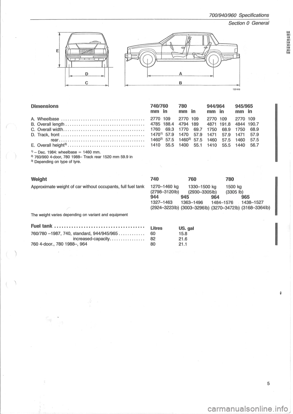
Dime ns io n s 7401760 780 944 /964 945/965
mm in mm in mm in mm in
A. Wheelbase .............................. . ...... . 2770 109 2770 109 2770
109 2770 109
B. Overall
length ................................... . 4785 188.4 4794
189 4871 191.8 4844 190.7
C. Overall width .................................... .
1760
69.3
1770 69.7
1750 68.9 1750 68.9
D. Track,
front ..................................... . 14701
) 57.9 1470 57.9 1471 57.9 1471 57.9
rear
................. ..................... . 14602
) 57.5 14602
) 57.5 1460 57.5 1460 57.5
E
. Overall height3
) ...... .........................•.•. 1410 55.5 1400 55.1 1410 55.5 1440 56.7
1) _ Dec. 1984: wheelbase = 1460 mm. 2) 760/960 4-door, 780 1988-Track
rear 1520 mm 59.9 in 3) Depending on type of tyre.
Weight 740
760 780
Approximate weight of car without occupants, fuWfuel tank 1270-1460 kg 1330-1500 kg 1500 kg
(2798-3120Ib) (2930-33051b) (3305 Ib)
944 945 964 965
1327-1463 1363-1496 1484-1576 1438-1527
,-(2924-3223Ib) (3003-3296Ib) (3270-3472lb) (3168-3364Ib)
The weight varies depending on variant and equipment
Fuel tank .................................... .
760/780 -1987,740, standard, 944/945/965 ........... .
increased-capacity
............... .
760 4 -door ., 780 1988-, 964
Litres
60
82
80
US. gal
15.8
21.6
21.1
5
I
Page 8 of 168
I
70019401960 Specifications
Section 0 General
1
~-
'''''~''''.' .. ~. . . , .... -. . .~. ," _. , . ..... ,. . . . . VOLV o . '
VOLVO _._N
C I, c , ,. .. , . I
4 C 3
r--8280 9A 150 873
740,760 ,940 ,960
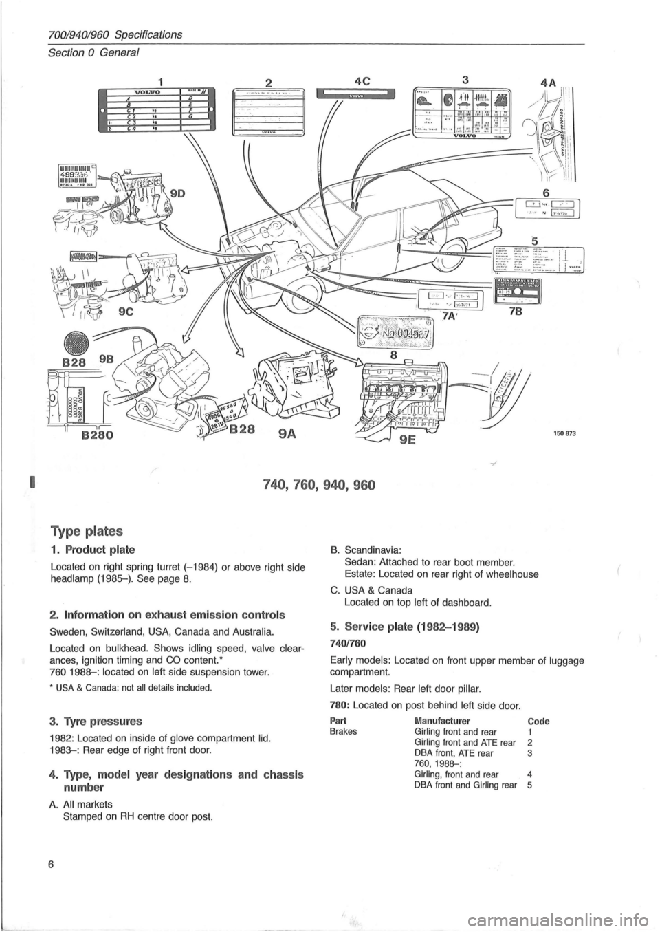
T ype p lates
1. P roduc t p la te
Located on right spring turret (-1984) or above right side
headlamp (1985-). See page 8.
2 . Inf ormation on exhau st emissio n co ntr ols
Sweden , Switzerland, USA, Canada and Australia.
Located on bulkhead. Shows idling speed, valve clear
ances, ignition timing and CO content. '
760 1988-: located on left side suspension tower.
* USA & Canada: not all details included .
3. Tyre p ress ures
1982 : Located on inside of glove compartment lid.
1983-: Rear edge of right front door.
4. Type, m ode l year des ig nat io ns a nd c hass is
numbe r
A. All markets
Stamped
on RH centre door post.
6
B. Scandinavia:
Sedan: Attached to rear boot member .
Estate: Located on rear right of
wheelhouse
C. USA & Canada
Located on top
left of dashboard.
5. Service pla te (1982-1 989 )
74 01760
Early models : Located on front upper member of luggage
compartment.
Later
models: Rear left door pillar.
780: Located on post behind left side door.
Part Brakes Manufactur er Girling front and rear Girling front and ATE rear
DBA front, ATE rear 760,1988-:
Code 1 2 3
Girling, front and rear 4
DBA front and Girling rear 5
(
Page 21 of 168
(
70019401960 Specifications
Section 2 B 19, B 23 Engines
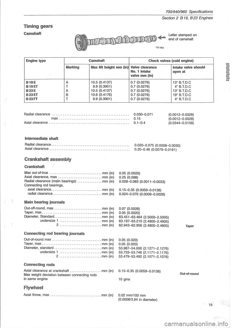
Timin g gears
Camshaft Letter stamped on
end ot camshaft
Engine type Camshaft
Check valves (cold engine)
Marking Max
lift height mm (in) Valve clearance
No.1 intake
valve mm (in)
B
19E A 10.5 (0.4137) 0.7 (0.0276)
B19ET T 9.9 (0.3901)
0.7 (0.0276)
B23E A 10.5 (0.4137) 0.7 (0.0276)
B23ET B 10.6 (0.4176) 0.7 (0.0276)
B23FT T 9.9 (0.3901)
0.7 (0.0276)
Radial clearance
............................................ 0.030-0 .071
max... . .... ... ............................... 0.15
Axial clearance . . . . . . . . . . . . . . . . . . . . . . . . . . . . . . . . . . . . . . . . . . . . . . 0.1-0.4
Int ermed iate shaft
Intake valve should
open at
13° B.T.D.C
4° B.T.D.C
13° B.TD.C
19° B.TD.C
4° B.iD.C
(0.0012-0 .0028)
(0.0012-0.0028)
(0.0344-0.0158)
Radial clearance.
. . . . . . . . . . . . . . . . . . . . . . . . . . . . . . . . . . . . . . . . . . . . 0.020-0.075 (0.0008-0.0030)
Axial clearance .
. . . . . . . . . . . . . . . . . . . . . . . . . . . . . . . . . . . . . . . . . . . . . 0.20-0.46 (0.0079-0.0181)
Crankshaft assembly
Crankshaft
Max out-ot-true .............................. mm (in)
Axial clearance, max ......................... mm (in)
Radial clearance (main bearings) .............. mm (in)
Connecting
rod bearings,
axial clearance ............................. mm (in)
radial clearance ............................ mm (in)
Main bearing journals
Out-oft-round, max ........................... mm (in)
Taper, max
.................................. mm (in)
Diameter, Standard .
.......................... mm (in)
undersize 1
........................ mm (in)
2 .
................ ....... mm (in)
Connecting rod bear ing journ als
Out-ot- round max ............................ mm (in)
Taper, max
.................................. mm (in)
Diameter, standard
........................... mm (in)
undersize 1
........................ mm (in)
2 ........................ mm (in)
Connecting rods
0.05 (0.0020)
0.25 (0.098)
0 :028-0.083 (0.0011-0.0033)
0.15-0.35 (0.0059-0.0138)
0 .024-0.070 (0.0009-0.0028)
0.07 (0.0028)
0.05 (0.0020)
63.451-63.464 (2.5000-2.5005)
63.197-63.210 (2.4900-2.4905)
62.943-62.956 (2.4800-2.4805)
0.05 (0.020)
0.05 (0.020)
53.987-54.000
(2.1271-2.1276)
53.733-53.746 (2.1171-2.1176)
53.479-53.492
(2.1071-2.1076)
Axial clearance
at crankshaft .................. mm (in) 0.15-0.35 (0.0059-0.0138)
Max weight deviation between connecting rods
in same engine 10 gms
Flywheel
Axial throw, max ............................. mm (in) 0.02 mm/100 mm
(0.0008/3.94 in diameter)
Taper
Out-of-round
19
1111 :111
111/ III III '
, III
III '
·111 III
"1
I
~J
Page 22 of 168
70019401960 Specifications
Section 2 B
19, B 23 Engines
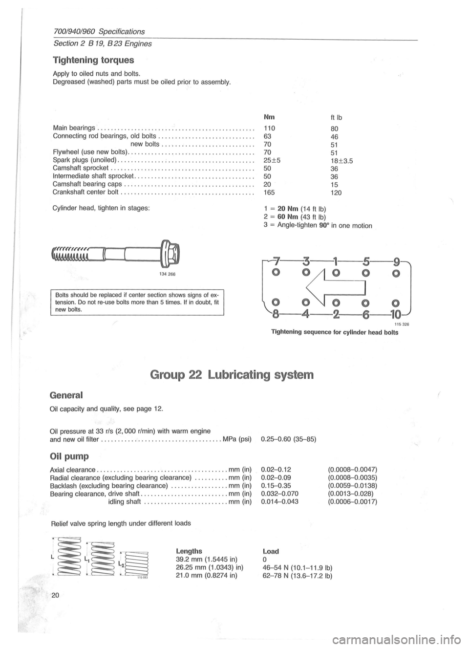
Tightening torques
Apply to oiled nuts and bolts.
Oegreased (washed) parts must be oiled prior to assembly.
Main bearings ....................... ' ....................... .
Connecting rod bearings,
old bolts ............................ .
new
bolts ......... .................. .
Flywheel (use new bolts) ..................................... .
Spark
plugs (unoiled) .............. ; ......................... .
Camshaft sprocket
............... ........................... .
Intermediate shaft sprocket ................................. .. .
Camshaft bearing caps .
............................ ......... .
Crankshaft center
bolt ....................................... .
Cylinder head , tighten in stages:
134266
Bolts should be replaced if center section shows signs of extension. Do not re-use bolts more than 5 times . If in doubt, fit
new bolts.
Nm
110
63
70
70
25±5
50
50 20
165
1 = 20 Nm (14 ft Ib)
2 = 60 Nm (43 ft Ib)
ft Ib
80
46
51
51
18±3.5
36
36 15
120
3 = Angle-tighten 900 in one motion
'7--3---
o 0
000
8-4-2-
--9
o
115326
Tightening sequence for cylinder head bolts
Group 22 Lubricating system
General
Oil capacity and quality, see page 12.
Oil pressure at 33 rls (2,000 r/min) with warm engine
and new
oil filter ...... .............................. MPa (psi) 0.25-0.60 (35-85)
Oil pump
Axial clearance .................. ..................... mm (in)
Radial clearance (excluding bearing clearance) .......... mm (in)
Backlash (excluding bearing clearance) ................. mm (in)
Bearing clearance, drive shaft
.......................... mm (in)
idling shaft ..... ........... .......... mm (in)
Relief valve spring length under different loads
~~~ 115083
20
Lengths
39.2 mm (1.5445 in)
26.25 mm (1.0343) in)
21.0 mm (0.8274 in)
0.02-0.12
0.02-0.09
0.15-0.35
0.032-0.070
0.014-0.043
Load
o
(0.0008-0 .0047)
(0.0008-0.0035)
(0.0059-0.0138)
(0.0013-0. 028)
(0.0006-0.0017)
46-54 N (10.1-11.9 Ib)
62 -78 N (13.6-17.2 Ib)
(
Page 43 of 168
(
70019401960 Specifications
Section
2 B 200, B 230 Engines
Bea rings
Main bearings
Two types of main bearings are in use. Upper and lower
shells
on same journal must be same type.
Connect
ing rod bearings
Matched
shells are used in production:
Shells are colour -coded (red, blue, yellow) as follows:
136753
Assembly 1 Two yellow shells.
Assembly
2 One blue and one red.
Blue shell in con-rod and red in cap.
Colour code Note that only yellow-coded shells are kept in stock .
• Late type: also main bearing shells .
Connect ing rods
Axial clearance at piston ............................... mm (in) 0.15-0.45 (0.0059-0.0177)
Max weight deviation between connecting
rods
in same engine ................................. gms (oz.) 20 (0.7)
Flywheel
Axial throw, max ...................................... mm (in) 0.021100 diameter (0.0008/3.9400)
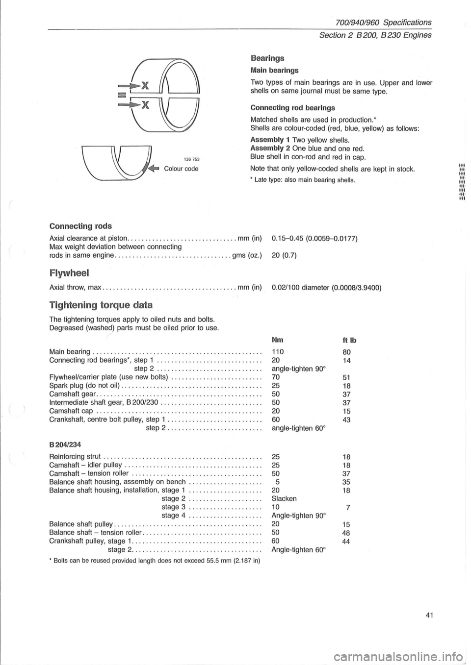
Tightening torque data
The tightening torques apply to oiled nuts and bolts.
Oegreased
(washed) parts must be oiled prior to use.
Main bearing
............................................... .
Connecting
rod bearings', step 1 ............................. .
step 2
............................. .
Flywheel/carrier plate (use new bolts) ...................... ... .
Spark plug (do not oil) ....................................... .
Camshaft gear
.............................................. .
Intermediate shaft gear, B 200/230 ............................ .
Camshaft cap
.............................................. .
Crankshaft, centre
bolt pulley, step 1 .......................... .
step 2 .
.. ....................... .
8204/234
Reinforcing strut ............................................ .
Camshaft -
idler pulley ...................................... .
Camshaft -tension
roller .................................... .
Balance shaft housing, assembly on bench .................... .
Balance shaft housing, installation, stage 1 .................... .
stage 2
.................... .
stage 3
.................... .
stage 4
.................... .
Balance shaft pulley ......................................... .
Balance shaft -tension roller .. ............................... .
Crankshaft
pulley, stage 1 .................................... .
stage 2
.................................... .
• Bolts can be reused provided length does not exceed 55.5 mm (2.187 in)
Nm
110
20
angle-tighten 90°
70
25
50
50
20
60
angle-tighten 60°
25
25
50
5
20
Slacken
10
Angle-tighten
90°
20
50
60
Angle-tighten 60°
ftlb
80
14
51
18
37
37
15
43
18
18
37
35
18
7
15
48
44
41
III :11' III II, III 'III III ,11' III
Page 75 of 168
{
Crank mec ha ni sm
Cr ank sh aft
Max run-out (measured on two centre main bearing journals) ..... .
Crankshaft, end float
........................................ .
clearance (main bearings) ......................... .
Crank
journals, side clearance ...........•.................... .
clearance .................................... .
M ain bea rin g journ als
Out of round, max ....................... .
Taper, max
...... ....................... .
Diameter, standard ...
................... .
undersized
.................... .
Conne cting rod b ea ring journ als
Out of round, max ....................... .
Taper, max
............................. .
Diameter, standard
...................... .
undersized
.................... .
C onnec tin g rods
0 .007 mm
0.01 mm
70.043-70.062 mm
69 .743-69.762 mm
0.007 mm
0.01 mm
52.267-52 .286 mm
51.967-51.986 mm
End
float on crankshaft (both can rods fitted) ................... .
Max weight difference between can rods
in same engine ........ .
Flywh eel
0.02 mm
0 .070-0.270 mm
0.038-0.088 mm
0.20-0.38 mm
0 .030-0.080 mm
0.0002 in
0.0003 in
2.7575-2.7583 in
2 .7457-2.7465 in
0.0002 in
0.0003 in
2.0577-2.0585 in
2.0456-2.0466 in
0.20-0.38 mm
2.5 grams
Axial throw, max . . . . . . . . . . . . . . . . . . . . . . . . . . . . . . . . . . . . . . . . . . . . . 0 .05 mm
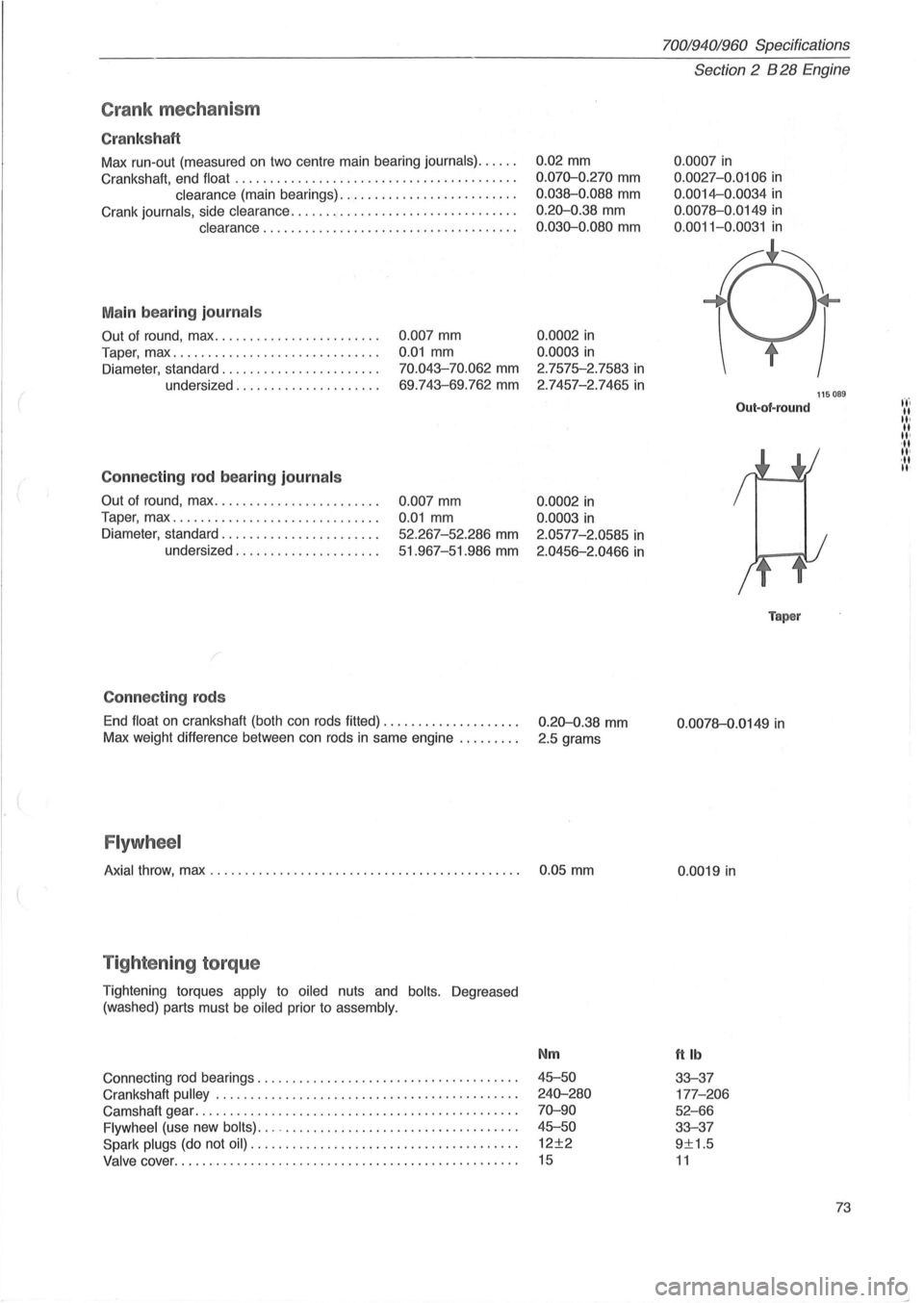
T ig hte nin g torq ue
Tightening torques apply to oiled nuts and bolts. Degreased
(washed) parts must be
oiled prior to assembly.
Connecting rod bearings ................. .......... ..... ..... .
Crankshaft
pulley . ........ .......... ........................ .
Camshaft gear
................................. ............. .
Flywheel (use new bolts) ... -................................. .
Spark plugs (do not oil) ...................................... .
Valve cover ......... .................................... .... .
Nm
45-50
240-280
70-90
45-50
12±2
15
70019401960 Specifications
Section 2 B 28 Engine
0 .0007 in
0.0027 -0.0106 in
0.0014-0.0034 in
0.0078-0 .0149 in
0 .0011-0.0031 in
Out-of-round
Taper
0 .0078-0.0149 in
0.0019 in
ttlb
33-37
177 -206
52-66
33-37
9±1.5
11
115089
73
t't'. -II II· II II' ,II II'
,II II'
Page 103 of 168
(
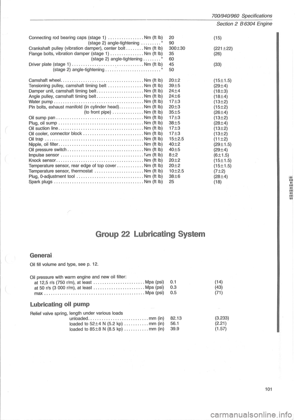
Connecting rod bearing caps (stage 1) ................ Nm (ft Ib)
(stage 2) angle-tightening ......... 0
Crankshaft pulley (vibration damper), center bolt ........ Nm (ft Ib)
Flange bolts, vibration damper (stage 1) ............... Nm (ft Ib)
(stage 2) angle-tightening ........ 0
Driver plate (stage 1) ......................... ....... Nm (ft Ib)
(stage 2) angle-tightening ......................... 0
Camshaft wheel. .................................... Nm (ft Ib)
Tensi oning pulley, camshaft timing belt ................ Nm (ft Ib)
Damper unit, camshaft timing belt ..................... Nm (ft Ib)
Angle pulley, camshaft timing belt ..................... Nm (ft Ib)
Water pump ........................................ Nm (ft Ib)
Pin bolts, exhaust manifold (in cylinder head) ........... Nm (ft Ib)
(to front pipe) .............. Nm (ft Ib)
Oil sump pan ....................................... Nm (ft Ib)
Plug, oil sump ...................................... Nm (ft Ib)
Oil suction line ...................................... Nm (ft Ib)
Oil cooler, connector block ........................... Nm (ft Ib)
Oil trap ............................................ Nm (ft Ib)
Nipple, oil·filter ...................................... Nm (ft Ib)
Oil pressure switch .................................. Nrn (ft Ib)
Impulse sensor ..................................... ~~m (ft Ib)
Knock sensor ....................................... Nm (ft Ib)
Temperature sensor, rear edge of top cover ............ Nm (ft Ib)
Temperature sensor, thermostat ............... ....... Nm (ft Ib)
Plug, O-adjustment tool .............................. Nm (ft Ib)
Spark plugs ... ..................................... Nm (ft Ib)
20
90
300±30
35
60 45
50
20±2
39±5
24±4
24±6
17±3
20±3
35±5
17±3
38±5
17±3
17±3
15±2.5
40±2
40±5
8±2
20±2
20±2
10±2.5
38±6
25
Group 22 Lubricating System
Genera l
Oil fill volume and type, see p. 12.
Oil pressure with warm engine and new oil filter :
at 12,5 rls (750 rim), at least ....... ................ Mpa (psi) 0.1
at
50 rls (3 000 rim), at least ....................... Mpa (psi) 0.3
max
...................... ....................... Mpa (psi) 0.5
Lubricat ing oil pump
Relief valve spring, length under various loads
unloaded
.................... ....... mm (in)
loaded to 52±4 N (5.2 kp) ....... .... mm (in)
loaded to 85±8 N (8.5 kp) ........... mm (in)
82.13
56.1
39.9
70019401960 Specifications
Section 2 B 6304 Engine
(15)
(221 ±22)
(26)
(33)
(15±1.5)
(29±4)
(18±3)
(18±4)
(13±2)
(15±2)
(26±4)
(13±2)
(28±4)
(13±2)
(13±2)
(11 ±2)
(29±1.5)
(29±4)
(6±1.5)
(15±1.5)
(15±1.5)
(7±2)
(28±4)
(18)
(14)
(43)
(71 )
(3.233) (2.21)
(1.57)
101
I ..... ' '.','
"' ,III III ill u,1
Page 114 of 168
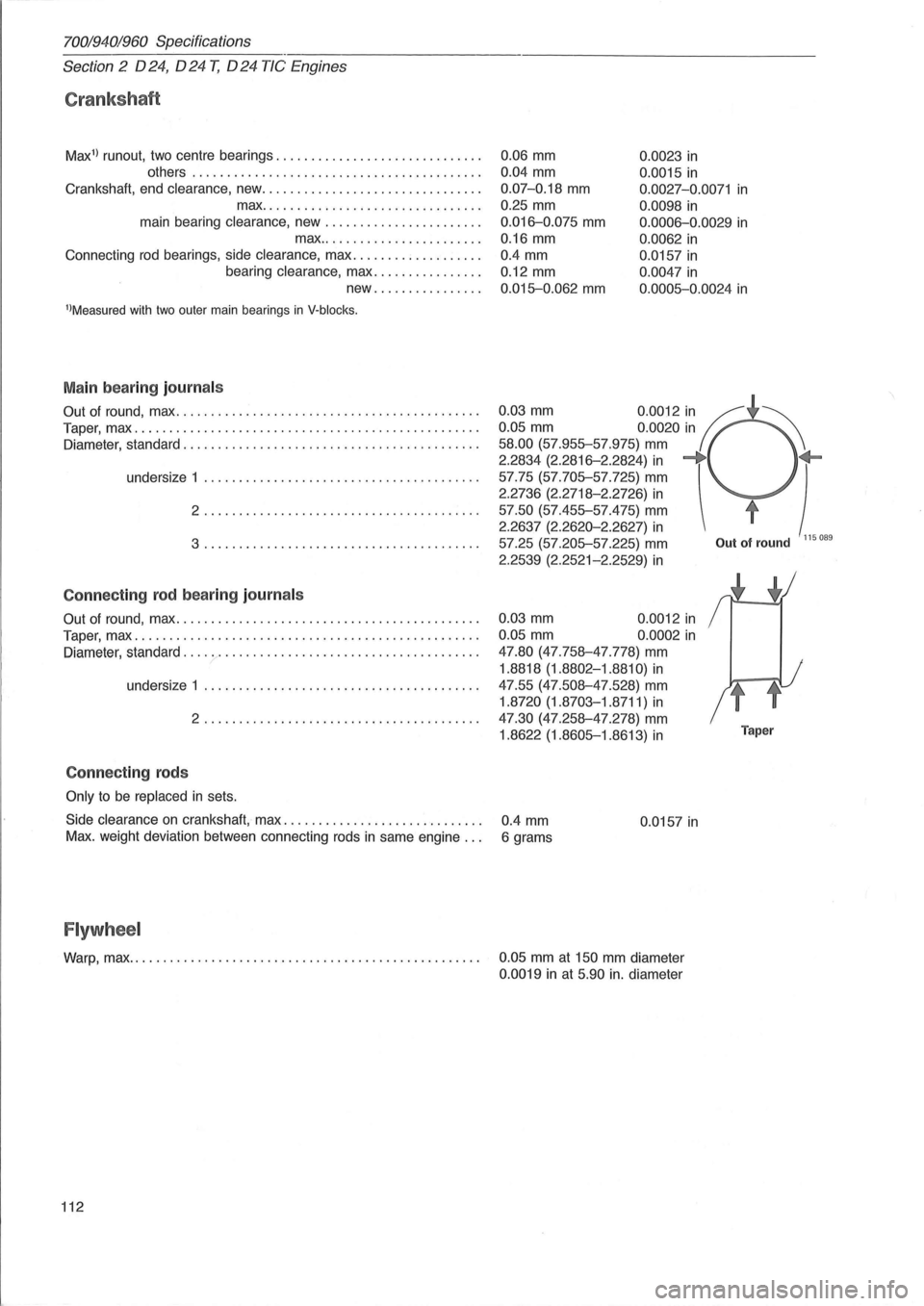
70019401960 Specifications
Section
2 024, 024 T, 024 TIC Engines
Crankshaft
Max1
) runout, two centre bearings ............................. .
others
........................................ . .
Crankshaft, end
clearance, new ............................... .
max .
.............................. .
main bearing
clearance, new ....... ............... .
max
....................... .
Connecting
rod bearings, side clearance, max .................. .
bearing
clearance, max ............... .
new
............... .
l)Measured with two outer main bearings in V·blocks.
Main bearing journal s
Out of round, max ........................................... .
Taper, max
................................................. .
Diameter, standard .
.................................... ..... .
undersize 1 .
...................................... .
2 ....................................... .
3 ......................... .............. .
Con necting rod bearing journ als
Out of round, max ........................................... .
Taper, max
................................................. .
Diameter, standard
.......................................... .
undersize 1
....................................... .
2
....................................... .
Con necting rods
Only to be replaced in sets.
0.06 mm 0.0023 in
0.04 mm
0.07-0.18 mm
0.25 mm
0.016-0.075 mm
0.16 mm
0.0015 in
0.0027-0.0071 in
0 .0098 in
0.0006-0.0029 in
0.0062 in
0.4 mm 0.0157 in
0.12 mm
0.015-0.062 mm
0.0047 in
0 .0005-0.0024 in
0.03 mm 0.0012 in If ~ 0.05 mm 0.0020 in
58.00 (57.955-57.975) mm
2.2834 (2.2816-2.2824) in -+ +-) 57.75 (57.705-57.725) mm
2.2736 (2.2718-2.2726) in
57.50 (57.455-57.475) mm t
2.2637 (2.2620-2.2627) in 57.25 (57.205-57.225) mm Out of round 115089
2.2539 (2.2521-2.2529) in
0.03 mm 0.0012 in
0.05 mm 0.0002 in
47.80 (47.758-47.778) mm
1.8818 (1.8802-1.8810) in
47.55 (47.508-47.528) mm
1.8720 (1.8703-1.8711) in
47.30 (47.258-47 .278) mm
1.8622 (1.8605-1.8613) in Taper
Side clearance on crankshaft, max. . . . . . . . . . . . . . . . . . . . . . . . . . . . . 0.4 mm 0.0157 in Max. weight deviation between connecting rods in same engine. . . 6 grams
Flywheel
Warp, max. . . . . . . . . . . . . . . . . . . . . . . . . . . . . . . . . . . . . . . . . . . . . . . . . . . 0.05 mm at 150 mm diameter
0.0019 in at 5.90 in. diameter
112
Page 115 of 168
(
70019401960 Specifications
Section
2 024, 024 T, 024 TIC Engines
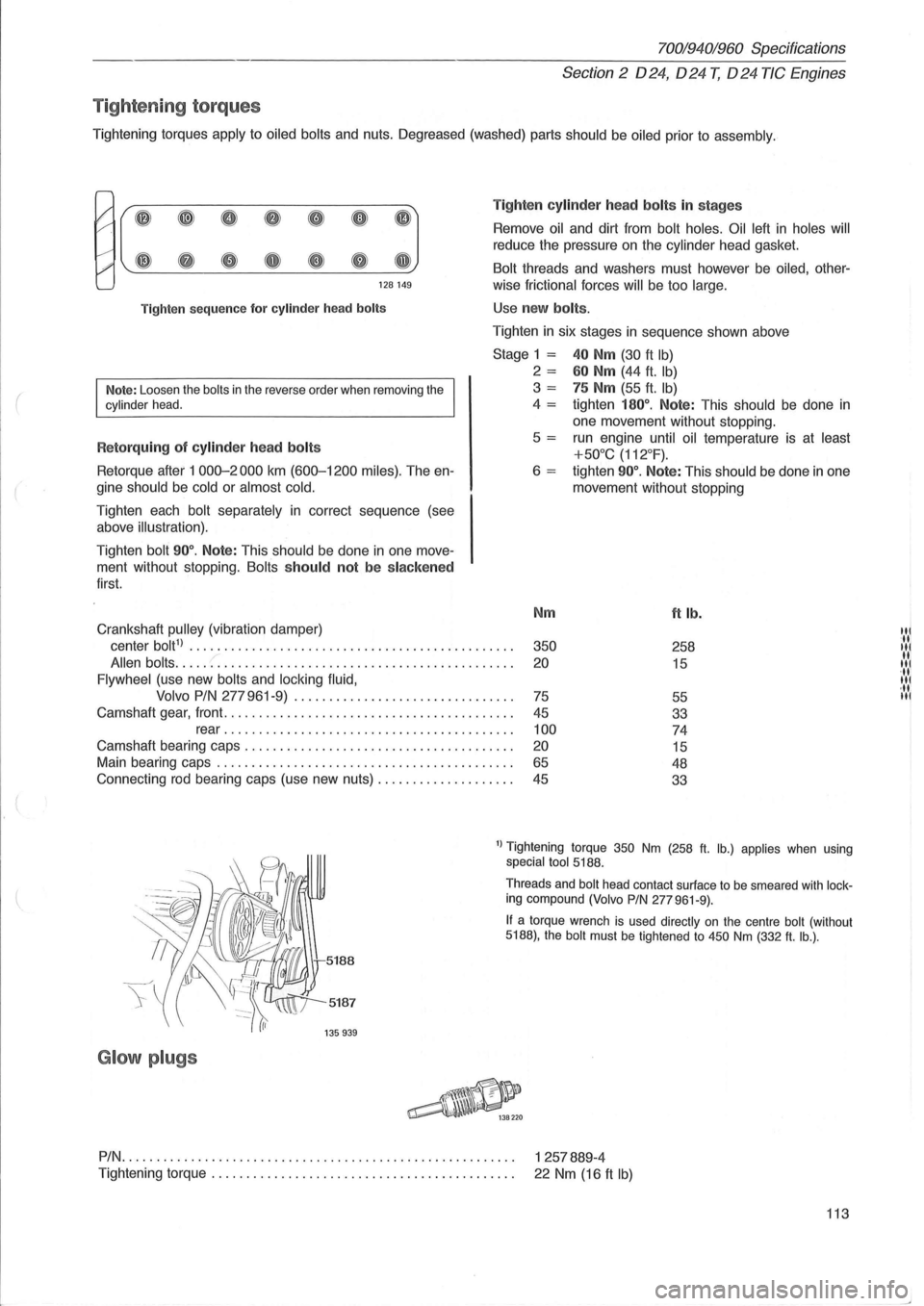
Tig ht enin g to rqu es
Tightening torques apply to oiled bolts and nuts. Oegreased (washed) parts should be oiled prior to assembly .
I' ~ ~ 0 8 CD 0 (IJ
#' ~ G e Q e Q GJ
128149
Tighten
sequence for cylinder head bolts
Note: Loosen the bolts in the reverse order when removing the cylinder head.
R etorquing of cylinder head bolts
Retorque after 1 000-2000 km (600-1200 miles). The en
gine
should be cold or almost cold.
Tighten each bolt separately in correct sequence (see
above
illustration).
Tighten bolt 90°. Note: This should be done in one move
ment without stopping.
Bolts should not be slacken ed
first.
Crankshaft
pulley (vibration damper) Ti
g
hten cylinde r h ea d bolts in stages
Remove oil and dirt from bolt holes. Oil left in holes will
reduce the pressure on the cylinder head gasket.
Bolt threads and washers must however be oiled, other-
wise
frictional forces will be too large.
Use new bolts .
Tighten in six stages in sequence shown above
Stage 1 = 40 Nm (30 ft Ib)
2 = 60 Nm (44 ft. Ib)
3 = 75 Nm (55 ft. Ib)
4 = tighten 180°. Note: This should be done in
one movement without stopping .
5
= run engine until oil temperature is at least
+50°C (112°F).
6 = tighten 90°. Note: This should be done in one
movement without stopping
Nm
ft lb.
center bolt1) ............................... ............... . 350 258
Allen bolts ..... :: ......................................... . 20 15
Flywheel (use new bolts and locking fluid,
Volvo PIN
277 961-9) ............................... .
75
55
Camshaft gear, front
......................................... .
45
33
rear
....................................... .. . 100 74
Camshaft bearing caps .................................... .. . 20 15
Main bearing caps .......................................... .
65 48
Connecting rod bearing caps (use new nuts)
................... .
45
33
1) Tightening torque 350 Nm (258 ft. lb.) applies when using special tool 5188.
5187
G lo w plugs
Threads and bolt head contact surface to be smeared with locking compound (Volvo PIN 277961-9).
If a torque wrench is used directly on the centre bolt (without 5188), the bolt must be tightened to 450 Nm (332 ft. lb.) .
PIN.
. . . . . . . . . . . . . . . . . . . . . . . . . . . . . . . . . . . . . . . . . . . . . . . . . . . . . . . . 1 257889-4
Tightening
torque. . . . . . . . . . . . . . . . . . . . . . . . . . . . . . . . . . . . . . . . . . . . 22 Nm (16 ft Ib)
113
'il IN 11 '11 11
·11 III