wheel size VOLVO 960 1982 Service Repair Manual
[x] Cancel search | Manufacturer: VOLVO, Model Year: 1982, Model line: 960, Model: VOLVO 960 1982Pages: 168, PDF Size: 54.28 MB
Page 21 of 168

(
70019401960 Specifications
Section 2 B 19, B 23 Engines
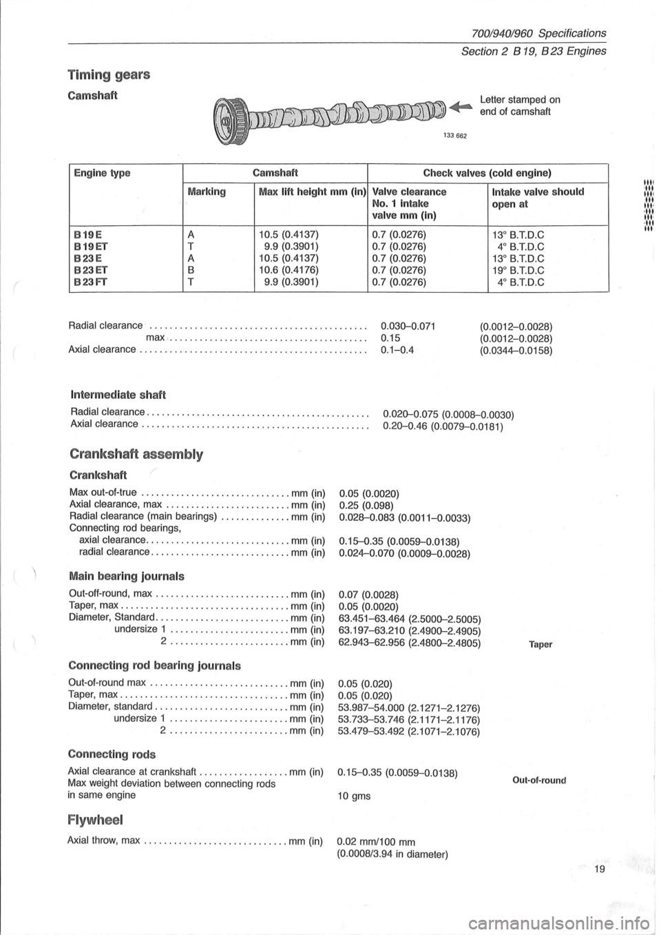
Timin g gears
Camshaft Letter stamped on
end ot camshaft
Engine type Camshaft
Check valves (cold engine)
Marking Max
lift height mm (in) Valve clearance
No.1 intake
valve mm (in)
B
19E A 10.5 (0.4137) 0.7 (0.0276)
B19ET T 9.9 (0.3901)
0.7 (0.0276)
B23E A 10.5 (0.4137) 0.7 (0.0276)
B23ET B 10.6 (0.4176) 0.7 (0.0276)
B23FT T 9.9 (0.3901)
0.7 (0.0276)
Radial clearance
............................................ 0.030-0 .071
max... . .... ... ............................... 0.15
Axial clearance . . . . . . . . . . . . . . . . . . . . . . . . . . . . . . . . . . . . . . . . . . . . . . 0.1-0.4
Int ermed iate shaft
Intake valve should
open at
13° B.T.D.C
4° B.T.D.C
13° B.TD.C
19° B.TD.C
4° B.iD.C
(0.0012-0 .0028)
(0.0012-0.0028)
(0.0344-0.0158)
Radial clearance.
. . . . . . . . . . . . . . . . . . . . . . . . . . . . . . . . . . . . . . . . . . . . 0.020-0.075 (0.0008-0.0030)
Axial clearance .
. . . . . . . . . . . . . . . . . . . . . . . . . . . . . . . . . . . . . . . . . . . . . 0.20-0.46 (0.0079-0.0181)
Crankshaft assembly
Crankshaft
Max out-ot-true .............................. mm (in)
Axial clearance, max ......................... mm (in)
Radial clearance (main bearings) .............. mm (in)
Connecting
rod bearings,
axial clearance ............................. mm (in)
radial clearance ............................ mm (in)
Main bearing journals
Out-oft-round, max ........................... mm (in)
Taper, max
.................................. mm (in)
Diameter, Standard .
.......................... mm (in)
undersize 1
........................ mm (in)
2 .
................ ....... mm (in)
Connecting rod bear ing journ als
Out-ot- round max ............................ mm (in)
Taper, max
.................................. mm (in)
Diameter, standard
........................... mm (in)
undersize 1
........................ mm (in)
2 ........................ mm (in)
Connecting rods
0.05 (0.0020)
0.25 (0.098)
0 :028-0.083 (0.0011-0.0033)
0.15-0.35 (0.0059-0.0138)
0 .024-0.070 (0.0009-0.0028)
0.07 (0.0028)
0.05 (0.0020)
63.451-63.464 (2.5000-2.5005)
63.197-63.210 (2.4900-2.4905)
62.943-62.956 (2.4800-2.4805)
0.05 (0.020)
0.05 (0.020)
53.987-54.000
(2.1271-2.1276)
53.733-53.746 (2.1171-2.1176)
53.479-53.492
(2.1071-2.1076)
Axial clearance
at crankshaft .................. mm (in) 0.15-0.35 (0.0059-0.0138)
Max weight deviation between connecting rods
in same engine 10 gms
Flywheel
Axial throw, max ............................. mm (in) 0.02 mm/100 mm
(0.0008/3.94 in diameter)
Taper
Out-of-round
19
1111 :111
111/ III III '
, III
III '
·111 III
"1
I
~J
Page 75 of 168

{
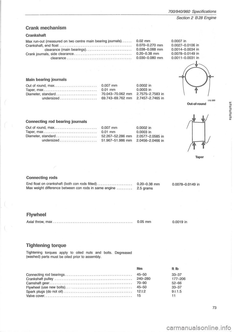
Crank mec ha ni sm
Cr ank sh aft
Max run-out (measured on two centre main bearing journals) ..... .
Crankshaft, end float
........................................ .
clearance (main bearings) ......................... .
Crank
journals, side clearance ...........•.................... .
clearance .................................... .
M ain bea rin g journ als
Out of round, max ....................... .
Taper, max
...... ....................... .
Diameter, standard ...
................... .
undersized
.................... .
Conne cting rod b ea ring journ als
Out of round, max ....................... .
Taper, max
............................. .
Diameter, standard
...................... .
undersized
.................... .
C onnec tin g rods
0 .007 mm
0.01 mm
70.043-70.062 mm
69 .743-69.762 mm
0.007 mm
0.01 mm
52.267-52 .286 mm
51.967-51.986 mm
End
float on crankshaft (both can rods fitted) ................... .
Max weight difference between can rods
in same engine ........ .
Flywh eel
0.02 mm
0 .070-0.270 mm
0.038-0.088 mm
0.20-0.38 mm
0 .030-0.080 mm
0.0002 in
0.0003 in
2.7575-2.7583 in
2 .7457-2.7465 in
0.0002 in
0.0003 in
2.0577-2.0585 in
2.0456-2.0466 in
0.20-0.38 mm
2.5 grams
Axial throw, max . . . . . . . . . . . . . . . . . . . . . . . . . . . . . . . . . . . . . . . . . . . . . 0 .05 mm
T ig hte nin g torq ue
Tightening torques apply to oiled nuts and bolts. Degreased
(washed) parts must be
oiled prior to assembly.
Connecting rod bearings ................. .......... ..... ..... .
Crankshaft
pulley . ........ .......... ........................ .
Camshaft gear
................................. ............. .
Flywheel (use new bolts) ... -................................. .
Spark plugs (do not oil) ...................................... .
Valve cover ......... .................................... .... .
Nm
45-50
240-280
70-90
45-50
12±2
15
70019401960 Specifications
Section 2 B 28 Engine
0 .0007 in
0.0027 -0.0106 in
0.0014-0.0034 in
0.0078-0 .0149 in
0 .0011-0.0031 in
Out-of-round
Taper
0 .0078-0.0149 in
0.0019 in
ttlb
33-37
177 -206
52-66
33-37
9±1.5
11
115089
73
t't'. -II II· II II' ,II II'
,II II'
Page 114 of 168

70019401960 Specifications
Section
2 024, 024 T, 024 TIC Engines
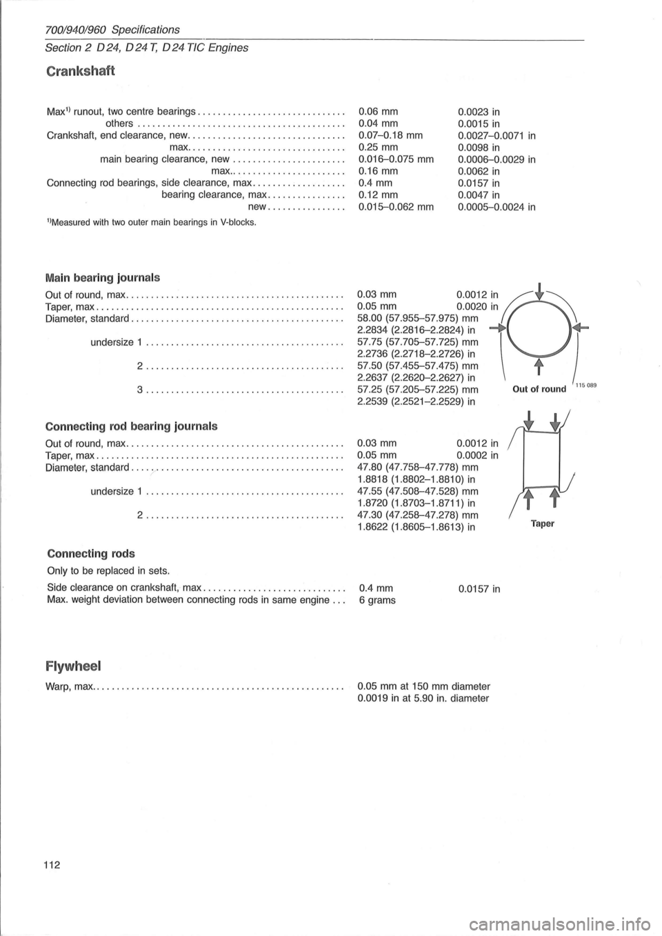
Crankshaft
Max1
) runout, two centre bearings ............................. .
others
........................................ . .
Crankshaft, end
clearance, new ............................... .
max .
.............................. .
main bearing
clearance, new ....... ............... .
max
....................... .
Connecting
rod bearings, side clearance, max .................. .
bearing
clearance, max ............... .
new
............... .
l)Measured with two outer main bearings in V·blocks.
Main bearing journal s
Out of round, max ........................................... .
Taper, max
................................................. .
Diameter, standard .
.................................... ..... .
undersize 1 .
...................................... .
2 ....................................... .
3 ......................... .............. .
Con necting rod bearing journ als
Out of round, max ........................................... .
Taper, max
................................................. .
Diameter, standard
.......................................... .
undersize 1
....................................... .
2
....................................... .
Con necting rods
Only to be replaced in sets.
0.06 mm 0.0023 in
0.04 mm
0.07-0.18 mm
0.25 mm
0.016-0.075 mm
0.16 mm
0.0015 in
0.0027-0.0071 in
0 .0098 in
0.0006-0.0029 in
0.0062 in
0.4 mm 0.0157 in
0.12 mm
0.015-0.062 mm
0.0047 in
0 .0005-0.0024 in
0.03 mm 0.0012 in If ~ 0.05 mm 0.0020 in
58.00 (57.955-57.975) mm
2.2834 (2.2816-2.2824) in -+ +-) 57.75 (57.705-57.725) mm
2.2736 (2.2718-2.2726) in
57.50 (57.455-57.475) mm t
2.2637 (2.2620-2.2627) in 57.25 (57.205-57.225) mm Out of round 115089
2.2539 (2.2521-2.2529) in
0.03 mm 0.0012 in
0.05 mm 0.0002 in
47.80 (47.758-47.778) mm
1.8818 (1.8802-1.8810) in
47.55 (47.508-47.528) mm
1.8720 (1.8703-1.8711) in
47.30 (47.258-47 .278) mm
1.8622 (1.8605-1.8613) in Taper
Side clearance on crankshaft, max. . . . . . . . . . . . . . . . . . . . . . . . . . . . . 0.4 mm 0.0157 in Max. weight deviation between connecting rods in same engine. . . 6 grams
Flywheel
Warp, max. . . . . . . . . . . . . . . . . . . . . . . . . . . . . . . . . . . . . . . . . . . . . . . . . . . 0.05 mm at 150 mm diameter
0.0019 in at 5.90 in. diameter
112
Page 161 of 168

(
700194019fiO Specifications
Section
7 Springs, dampers and wheels
Section 7 Springs, shock absorbers, wheels
Group 77 Wheels, tires, hubs
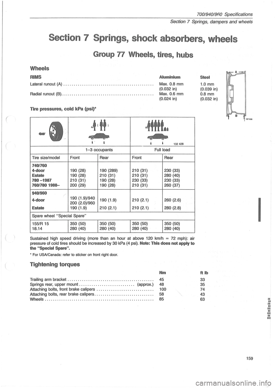
Wheels
RIMS Aluminium
Lateral runout (A) . . . . . . . . . . . . . . . . . . . . . . . . . . . . . . . . . . . . . . . . . . . . Max. 0.8 mm
(0.032 in)
Radial runout (8). . . . . . . . . . . . . . . . . . . . . . . . . . . . . . . . . . . . . . . . . . . . . Max. 0.6 mm
(0.024 in)
Tire pressures , cold kPa (ps i)*
~tttt*.
-e-US , I 132428
Tire size/model
7401760
4-door
Estate
780 - 1987
7601780 1988-
940/960
4-doo r
Estate
Front
190 (28)
190 (28)
210 (31)
200 (29)
1-3 occupants
Rear
190 (289)
210 (31)
190 (28)
190 (28)
190 (1.9)/940 190 (1.9)
200 (2.0)/960
190 (1.9) 210 (2.1)
Spare wheel "Special Spare"
155/R 15
18.14 350
(50)
280 (40) 350
(50)
280 (40) Front
210 (31)
210 (31)
230 (33)
210 (31)
210 (2.1)
210 (2.1)
350 (50)
280 (40)
Full load
Rear
230 (33)
280 (40)
230 (33)
260 (37)
260 (2.6)
280 (2.8)
350 (50)
280 (40)
Sustained high speed driving (more than an hour at above 120 kmlh
= 72 mph) : air
pressure of
cold tires should be increased by 30 kPa (4 psi). Note: This does not apply to
the "Spec ia l Spare " .
• For USA/Canada: refer to sticker on front right door.
Tightening torques
Nm
Trailing arm bracket ......................................... .
45
Springs
rear, upper mount. . . . . . . . . . . . . . . . . . . . . . . . . .. (approx.) 48
Attaching
bolts, front brake calipers ............. .............. . 100
Attaching bolts, rear brake calipers ............................ . 58
Whe e
ls .................................................... .
85
Stee l
1.0 mm
(0.039 in)
0.8
mm
(0.032 in)
ttlb
33
35
74
43
63
159
I
III .. III II III ... III ·11 III