reset VOLVO C30 2013 Owner´s Manual
[x] Cancel search | Manufacturer: VOLVO, Model Year: 2013, Model line: C30, Model: VOLVO C30 2013Pages: 300, PDF Size: 6.58 MB
Page 16 of 300
Introduction
Important warnings
14
Driver distraction
A driver has a responsibility to do everything
possible to ensure his or her own safety and
the safety of passengers in the vehicle and oth-
ers sharing the roadway. Avoiding distractions
is part of that responsibility.
Driver distraction results from driver activities
that are not directly related to controlling the
vehicle in the driving environment. Your new
Volvo is, or can be, equipped with many fea-
ture-rich entertainment and communication
systems. These include hands-free cellular tel-
ephones, navigation systems, and multipur-
pose audio systems. You may also own other
portable electronic devices for your own con-
venience. When used properly and safely, they
enrich the driving experience. Improperly used,
any of these could cause a distraction.
For all of these systems, we want to provide the
following warning that reflects the strong Volvo
concern for your safety. Never use these devi-
ces or any feature of your vehicle in a way that
distracts you from the task of driving safely.
Distraction can lead to a serious accident. In
addition to this general warning, we offer the
following guidance regarding specific newer
features that may be found in your vehicle:
•Never use a hand-held cellular telephone
while driving. Some jurisdictions prohibitcellular telephone use by a driver while the
vehicle is moving.
•If your vehicle is equipped with a naviga-
tion system, set and make changes to your
travel itinerary only with the vehicle parked.
•Never program your audio system while
the vehicle is moving. Program radio pre-
sets with the vehicle parked, and use your
programmed presets to make radio use
quicker and simpler.
•Never use portable computers or personal
digital assistants while the vehicle is mov-
ing.
Accessory installation
•We strongly recommend that Volvo owners
install only genuine, Volvo-approved
accessories, and that accessory installa-
tions be performed only by a trained and
qualified Volvo service technician.
•Genuine Volvo accessories are tested to
ensure compatibility with the performance,
safety, and emission systems in your vehi-
cle. Additionally, a trained and qualified
Volvo service technician knows where
accessories may and may not be safely
installed in your Volvo. In all cases, please
consult a trained and qualified Volvo serv-
ice technician before installing any acces-
sory in or on your vehicle.
•Accessories that have not been approved
by Volvo may or may not be specifically
tested for compatibility with your vehicle.
Additionally, an inexperienced installer
may not be familiar with some of your car's
systems.
•Any of your car's performance and safety
systems could be adversely affected if you
install accessories that Volvo has not tes-
ted, or if you allow accessories to be instal-
led by someone unfamiliar with your vehi-
cle.
•Damage caused by unapproved or
improperly installed accessories may not
be covered by your new vehicle warranty.
See your Warranty and Service Records
Information booklet for more warranty
information. Volvo assumes no responsi-
bility for death, injury, or expenses that
may result from the installation of non-gen-
uine accessories.
Page 39 of 300

01 Safety
Crash mode01
37 Driving after a collision
G026363
If the vehicle has been involved in a collision,
the text CRASH MODE SEE MANUAL may
appear in the information display. This indi-
cates that the vehicle's functionality has been
reduced.
This text can only be shown if the display is
undamaged and the vehicle's electrical system
is intact.
CRASH MODE is a feature that is triggered if
one or more of the safety systems (for example,
front or side airbags, an inflatable curtain, or
one or more of the seat belt pretensioners) has
deployed. The collision may have damaged an
important function in the vehicle, such as thefuel lines, sensors for one of the safety sys-
tems, the brake system, etc.
WARNING
•Never attempt to repair the vehicle
yourself or to reset the electrical system
after the vehicle has displayed
CRASH
MODE SEE MANUAL. This could
result in injury or improper system func-
tion.
•Restoring the vehicle to normal operat-
ing mode should only be done by a
trained and qualified Volvo service tech-
nician.
•After CRASH MODE SEE MANUALhas been displayed, if you detect the
odor of fuel vapor, or see any signs of
fuel leakage, do not attempt to start the
vehicle. Leave the vehicle immediately.
Attempting to start the vehicleIf damage to the vehicle is minor and there is
no fuel leakage, you may attempt to start the
vehicle. To do so:
1. Remove the ignition key or optional keyless
drive start control, see page 152.
2. Reinsert the key or start control in the igni-
tion switch. The vehicle will then attempt to
reset CRASH MODE to normal mode.3. Try to start the vehicle.
Moving the vehicleIf the electrical system is able to reset system
status to normal (CRASH MODE SEE
MANUAL will no longer be displayed), the
vehicle may be moved carefully from its pres-
ent position, if for example, it is blocking traffic.
It should, however, not be moved farther than
is absolutely necessary.
WARNING
Even if the vehicle appears to be drivable
after CRASH MODE has been set, it should
not be driven or towed (pulled by another
vehicle). There may be concealed damage
that could make it difficult or impossible to
control. The vehicle should be transported
on a flatbed tow truck to a trained and quali-
fied Volvo service technician for inspection/
repairs.
Page 57 of 300

02 Instruments and controls
Instrument panel
02
55
odometer, trip odometers, optional rain
sensor, and cruise control.
Trip odometer reset button – The trip
odometers are used to measure short dis-
tances. Press the button briefly to switch
between the odometer for the car's total
mileage and the two trip odometers, T1
and T2. A long press (more than 2 seconds)
resets the currently selected trip odometer.
Temperature gauge – The gauge indicates
the temperature of the engine cooling sys-
tem. If the temperature is abnormally high
and the needle enters the red zone, a mes-
sage is shown in the display. Bear in mind
that auxiliary lamps in front of the air intake
reduce the cooling capacity at high outside
temperatures and high engine loads.
Indicator and warning symbols
Page 63 of 300
02 Instruments and controls
Information display
02
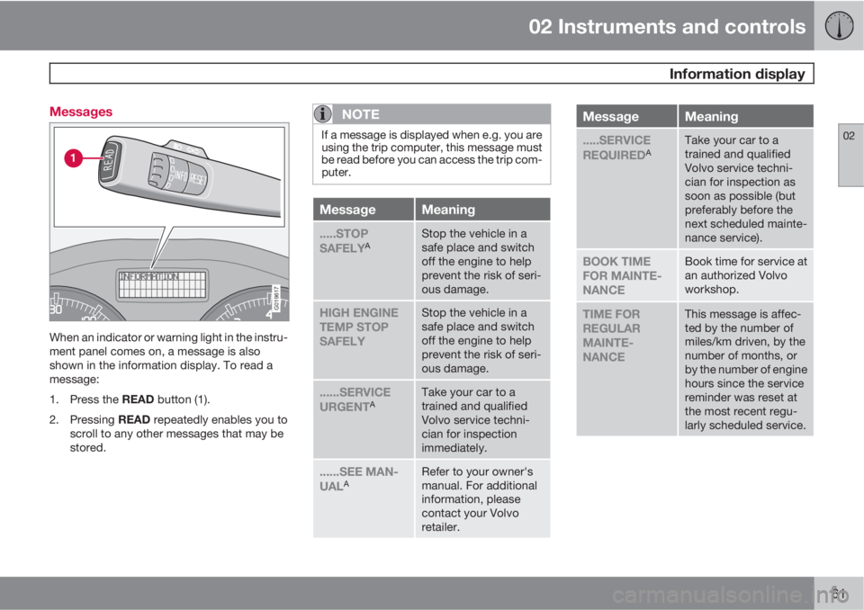
61 Messages
G019617
When an indicator or warning light in the instru-
ment panel comes on, a message is also
shown in the information display. To read a
message:
1.
Press the READ button (1).
2.
Pressing READ repeatedly enables you to
scroll to any other messages that may be
stored.
NOTE
If a message is displayed when e.g. you are
using the trip computer, this message must
be read before you can access the trip com-
puter.
MessageMeaning
.....STOP
SAFELYAStop the vehicle in a
safe place and switch
off the engine to help
prevent the risk of seri-
ous damage.
HIGH ENGINE
TEMP STOP
SAFELYStop the vehicle in a
safe place and switch
off the engine to help
prevent the risk of seri-
ous damage.
......SERVICE
URGENTATake your car to a
trained and qualified
Volvo service techni-
cian for inspection
immediately.
......SEE MAN-
UALARefer to your owner's
manual. For additional
information, please
contact your Volvo
retailer.
MessageMeaning
.....SERVICE
REQUIREDATake your car to a
trained and qualified
Volvo service techni-
cian for inspection as
soon as possible (but
preferably before the
next scheduled mainte-
nance service).
BOOK TIME
FOR MAINTE-
NANCEBook time for service at
an authorized Volvo
workshop.
TIME FOR
REGULAR
MAINTE-
NANCEThis message is affec-
ted by the number of
miles/km driven, by the
number of months, or
by the number of engine
hours since the service
reminder was reset at
the most recent regu-
larly scheduled service.
Page 72 of 300
02 Instruments and controls
Trip computer
02
70
G029052
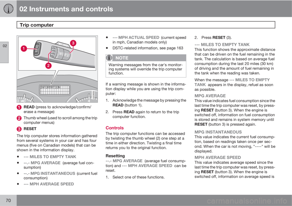
READ (press to acknowledge/confirm/
erase a message)
Thumb wheel (used to scroll among the trip
computer menus)
RESET
The trip computer stores information gathered
from several systems in your car and has four
menus (five on Canadian models) that can be
shown in the information display.
•--- MILES TO EMPTY TANK
•--.- MPG AVERAGE (average fuel con-
sumption)
•--.- MPG INSTANTANEOUS (current fuel
consumption)
•--- MPH AVERAGE SPEED
•--- MPH ACTUAL SPEED (current speed
in mph, Canadian models only)
•DSTC-related information, see page 163
NOTE
Warning messages from the car's monitor-
ing systems will override the trip computer
function.
If a warning message is shown in the informa-
tion display while you are using the trip com-
puter:
1. Acknowledge the message by pressing the
READ (button 1).
2.
Press READ again to return to the trip
computer function.
Controls
The trip computer functions can be accessed
by twisting the thumb wheel (2) one step at a
time in either direction. Twisting a final time
returns you to the original function.
Resetting
--.- MPG AVERAGE (average fuel consump-
tion) and --- MPH AVERAGE SPEED can be
reset.
1. Select one of these functions.2.
Press RESET (3).
--- MILES TO EMPTY TANKThis function shows the approximate distance
that can be driven on the fuel remaining in the
tank. The calculation is based on average fuel
consumption during the last 20 miles (30 km)
of driving and the amount of fuel remaining in
the tank when the reading was taken.
When the message
--- MILES TO EMPTY
TANK appears in the display, refuel as soon
as possible.
MPG AVERAGEThis value indicates fuel consumption since the
last time the trip computer was reset, by press-
ing RESET (button 3). When the engine is
switched off, information on fuel consumption
is stored and remains in system memory until
RESET (button 3) is pressed again.
MPG INSTANTANEOUSThis value indicates the current fuel consump-
tion, based on readings taken once per sec-
ond. When the car is not moving, "
----" will be
displayed.
MPH AVERAGE SPEEDThis value indicates average speed since the
last time the trip computer was reset, by press-
ing RESET (button 3). When the engine is
switched off, information on average speed is
Page 73 of 300
02 Instruments and controls
Trip computer
02
71
stored and remains in system memory until the
RESET (button 3) is pressed again.
MPH ACTUAL SPEED (Canadian models
only)
This function provides the driver with an instan-
taneous conversion of the car's current speed
from km/h to mph.
NOTE
Trip computer readings may vary slightly
depending on the circumference of the tires
on the car, tire inflation, or driving style.
Page 88 of 300
02 Instruments and controls
Personal settings
02
86
•Both front doors – both front doors are
unlocked together.
•One front door – either of the front doors
can be unlocked separately2.
Reset to factory settingsUse this alternative to return to the default cli-
mate system settings.
2Factory default.
Page 89 of 300
02 Instruments and controls
HomeLink® Wireless Control System*
02
* Option/accessory, for more information, see Introduction.87 Introduction
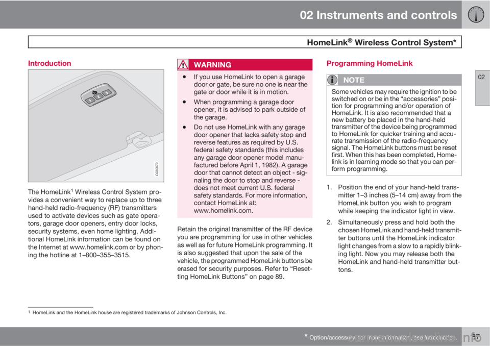
G030070
The HomeLink1 Wireless Control System pro-
vides a convenient way to replace up to three
hand-held radio-frequency (RF) transmitters
used to activate devices such as gate opera-
tors, garage door openers, entry door locks,
security systems, even home lighting. Addi-
tional HomeLink information can be found on
the Internet at www.homelink.com or by phon-
ing the hotline at 1–800–355–3515.
WARNING
•If you use HomeLink to open a garage
door or gate, be sure no one is near the
gate or door while it is in motion.
•When programming a garage door
opener, it is advised to park outside of
the garage.
•Do not use HomeLink with any garage
door opener that lacks safety stop and
reverse features as required by U.S.
federal safety standards (this includes
any garage door opener model manu-
factured before April 1, 1982). A garage
door that cannot detect an object - sig-
naling the door to stop and reverse -
does not meet current U.S. federal
safety standards. For more information,
contact HomeLink at:
www.homelink.com.
Retain the original transmitter of the RF device
you are programming for use in other vehicles
as well as for future HomeLink programming. It
is also suggested that upon the sale of the
vehicle, the programmed HomeLink buttons be
erased for security purposes. Refer to “Reset-
ting HomeLink Buttons” on page 89.
Programming HomeLink
NOTE
Some vehicles may require the ignition to be
switched on or be in the “accessories” posi-
tion for programming and/or operation of
HomeLink. It is also recommended that a
new battery be placed in the hand-held
transmitter of the device being programmed
to HomeLink for quicker training and accu-
rate transmission of the radio-frequency
signal. The HomeLink buttons must be reset
first. When this has been completed, Home-
link is in learning mode so that you can per-
form programming.
1. Position the end of your hand-held trans-
mitter 1–3 inches (5–14 cm) away from the
HomeLink button you wish to program
while keeping the indicator light in view.
2. Simultaneously press and hold both the
chosen HomeLink and hand-held transmit-
ter buttons until the HomeLink indicator
light changes from a slow to a rapidly blink-
ing light. Now you may release both the
HomeLink and hand-held transmitter but-
tons.
1HomeLink and the HomeLink house are registered trademarks of Johnson Controls, Inc.
Page 91 of 300
02 Instruments and controls
HomeLink® Wireless Control System*
02
* Option/accessory, for more information, see Introduction.89
NOTE
If the ignition is switched off, HomeLink will
function for 30 minutes after the driver's
door has been opened.
Resetting HomeLink Buttons
Use the following procedure to reset (erase
programming) from the three HomeLink but-
tons (individual buttons cannot be reset but
can be “reprogrammed” as outlined in the fol-
lowing section):
1. Press and hold the two outer HomeLink
buttons until the indicator light begins to
flash.
2. Release both buttons.
> HomeLink is now in the training (or
learning) mode and can be programmed
at any time beginning with “Program-
ming” - step 1.
Reprogramming a Single HomeLink
Button
To program a device to HomeLink using a
HomeLink button previously trained, follow
these steps:
1. Press and hold the desired HomeLink but-
ton. DO NOT release the button.
2. The indicator light will begin to flash after
20 seconds. Without releasing the Home-
Link button, proceed with “Programming”
- step 1.
For questions or comments, contact HomeLink
at: www.homelink.com or phone 1–800–355–
3515.
This device complies with FCC rules part 15
and Industry Canada (IC) RSS-210. Operation
is subject to the following two conditions: (1)
This device may not cause harmful interfer-
ence, and (2) This device must accept any
interference that may be received including
interference that may cause undesired opera-
tion.
NOTE
The transmitter has been tested and com-
plies with FCC and IC rules. Changes or
modifications not expressly approved by
the party responsible for compliance could
void the user’s authority to operate the
device.
2
2The term “IC:” before the certification/registration number only signifies that Industry Canada technical specifications were met.
Page 112 of 300
04 Interior
Front seats
04
110* Option/accessory, for more information, see Introduction.
NOTE
Both front seats are equipped with head
restraints that can be adjusted vertically to
suit the height of the passenger. The upper
edge of the head restraint should be at least
on a level with the upper-most point of the
seat occupant's ear (see the section
"Adjusting the front seat head restraints" on
page 111).
NOTE
The power seats have an overload protector
that activates if a seat is blocked by any
object. If this occurs, switch off the ignition
(key in position 0) and wait for approxi-
mately 20 seconds before operating the
seat again.
Emergency stopIf the seat inadvertently begins to move, press
any of the buttons to stop the seat.
Programming the seat memory, driver's
seat only*
G020200
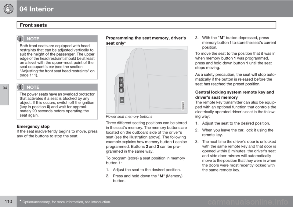
Power seat memory buttons
Three different seating positions can be stored
in the seat's memory. The memory buttons are
located on the outboard side of the driver's
seat (see the illustration above). The following
example explains how memory button 1 can be
programmed. Buttons 2 and 3 can be pro-
grammed in the same way.
To program (store) a seat position in memory
button 1:
1. Adjust the seat to the desired position.
2.
Press and hold down the "M" (Memory)
button.3.
With the "M" button depressed, press
memory button 1 to store the seat's current
position.
To move the seat to the position that it was in
when memory button 1 was programmed,
press and hold down button 1 until the seat
stops moving.
As a safety precaution, the seat will stop auto-
matically if the button is released before the
seat has reached the preset position.
Central locking system remote key and
driver's seat memory
The remote key transmitter can also be equip-
ped with an optional function that controls the
electrically operated driver's seat in the follow-
ing way:
1. Adjust the seat to the desired position.
2. When you leave the car, lock it using the
remote key.
3. The next time the driver's door is unlocked
with the same remote key and that door is
opened within 2 minutes, the driver's seat
and side door mirrors will automatically
move to the position that they were in when
the doors were most recently locked with
the same remote key.