transmission VOLVO C30 2013 Owner´s Manual
[x] Cancel search | Manufacturer: VOLVO, Model Year: 2013, Model line: C30, Model: VOLVO C30 2013Pages: 300, PDF Size: 6.58 MB
Page 6 of 300
Contents
4* Option/accessory, for more information, see Introduction.
06
06 Starting and driving
General information................................142
Fuel requirements................................... 146
Ignition switch......................................... 149
Starting the vehicle................................. 150
Starting the vehicle with keyless drive*... 152
Manual transmission, 6-speed*.............. 154
Automatic transmission..........................155
Shiftlock override.................................... 158
Brake system.......................................... 159
Parking brake.......................................... 162
Stability system....................................... 163
Towing.................................................... 165
Jump starting.......................................... 168
Transporting loads.................................. 169
Blind Spot Information System (BLIS)*. . . 170
Rear park assist*..................................... 174
07
07 Wheels and tires
General information................................178
Tire inflation............................................. 181
Inflation pressure ...................................183
Tire designations..................................... 184
Glossary of tire terminology.................... 186
Vehicle loading........................................ 187
Uniform tire quality gradings................... 188
Snow chains, snow tires, studded tires. . 189
Tire Sealing System* .............................. 190
Temporary spare..................................... 196
Spare tire and jack .................................197
Wheel nuts.............................................. 199
Changing a wheel................................... 200
Tire Pressure Monitoring System (TPMS) 202
08
08 Car care
Washing and cleaning the car................. 208
Paint touch up......................................... 212
Page 13 of 300

Introduction
Important information
11
Shiftlock (automatic transmission)When your vehicle is parked, the gear selector
is locked in the P (Park) position. To release the
selector from this position, turn the ignition key
to position II (or start the engine), depress the
brake pedal, press the button on the front side
of the gear selector and move the selector from
P (Park).
Keylock (automatic transmission)When you switch off the ignition, the gear
selector must be in the P (Park) position before
the remote key can be removed from the igni-
tion switch.
Anti-lock Brake System (ABS)The ABS system in your vehicle performs a
self-diagnostic test when the vehicle first rea-
ches the speed of approximately 12 mph
(20 km/h). The brake pedal will pulsate several
times and a sound may be audible from the
ABS control module. This is normal.
Fuel filler doorPress the button on the light switch panel (see
the illustration on page 67) when the vehicle
is at a standstill to unlock the fuel filler door.
Please note that the fuel filler door will remain
unlocked until the vehicle begins to move for-
ward. An audible click will be heard when the
fuel filler door relocks.
Points to keep in mind
•Do not export your Volvo to another coun-
try before investigating that country's
applicable safety and exhaust emission
requirements. In some cases it may be dif-
ficult or impossible to comply with these
requirements. Modifications to the emis-
sion control system(s) may render your
Volvo not certifiable for legal operation in
the U.S., Canada and other countries.
•All information, illustrations and specifica-
tions contained in this manual are based on
the latest product information available at
the time of publication. Please note that
some vehicles may be equipped differ-
ently, depending on special legal require-
ments. Optional equipment described in
this manual may not be available in all mar-
kets.
•Volvo reserves the right to make model
changes at any time, or to change specifi-
cations or design without notice and with-
out incurring obligation.
Volvo Structural Parts Statement
Volvo has always been and continues to be a
leader in automotive safety. Volvo engineers
and manufactures vehicles designed to help
protect vehicle occupants in the event of a col-
lision.
Volvos are designed to absorb the impact of a
collision. This energy absorption system
including, but not limited to, structural compo-
nents such as bumper reinforcement bars,
bumper energy absorbers, frames, rails, fender
aprons, A-pillars, B-pillars and body panels
must work together to maintain cabin integrity
and protect the vehicle occupants.
The supplemental restraint system including
but not limited to air bags, side curtain air bags,
and deployment sensors work together with
the above components to provide proper tim-
ing for air bag deployment.
Due to the above, Volvo Cars of North America
does not support the use of aftermarket, alter-
native or anything other than original Volvo
parts for collision repair.
In addition Volvo does not support the use or
re-use of structural components from an exist-
ing vehicle that has been previously damaged.
Although these parts may appear equivalent, it
is difficult to tell if the parts have been previ-
ously replaced with non-OE parts or if the part
has been damaged as a result of a prior colli-
Page 25 of 300

01 Safety
Supplemental Restraint System01
23 Supplemental Restraint System (SRS)
G026330
SRS warning light
As an enhancement to the three-point seat
belts, your Volvo is equipped with a Supple-
mental Restraint System (SRS). Volvo's SRS
consists of seat belt pretensioners, front air-
bags, side impact airbags, the occupant
weight sensor, and inflatable curtains. All of
these systems are monitored by the SRS con-
trol module. An SRS warning light in the instru-
ment panel (see the illustration) illuminates
when the ignition key is turned to position I, II,
or III, and will normally go out after approxi-
mately 7 seconds if no faults are detected in
the system.Where applicable, a text message will also be
displayed when the SRS warning light illumi-
nates. If this warning symbol is not functioning
properly, the general warning symbol illumi-
nates and either
SRS AIRBAG SERVICE
URGENT or SRS AIRBAG SERVICE
REQUIREDwill be displayed.
WARNING
•If the SRS warning light stays on after
the engine has started or if it illuminates
while you are driving, have the vehicle
inspected by a trained and qualified
Volvo service technician as soon as
possible.
•Never try to repair any component or
part of the SRS yourself. Any interfer-
ence in the system could cause mal-
function and serious injury. All work on
these systems should be performed by
a trained and qualified Volvo service
technician.
WARNING
If your vehicle has been subjected to flood
conditions (e.g. soaked carpeting/standing
water on the floor of the vehicle) or if your
vehicle has become flood-damaged in any
way, do not attempt to start the vehicle or
put the key in the ignition before discon-
necting the battery (see below). This may
cause airbag deployment which could result
in personal injury. Have the vehicle towed to
a trained and qualified Volvo service tech-
nician for repairs.
Automatic transmission
Before attempting to tow the vehicle, use
the following procedure to override the
shiftlock system to move the gear selector
to the neutral position:
1. Switch off the ignition for at least
10 minutes and disconnect the battery.
2. Wait at least one minute.
3. Insert the key in the ignition and turn it
to position II.
4. Press firmly on the brake pedal.
5.
Move the gear selector from Park (P) to
the Neutral (N) position, see page 158,
for information on manually overriding
the shiftlock system.
Page 78 of 300
02 Instruments and controls
Right-side steering wheel lever
02
76
•Intermittent wiping: Press in the upper sec-
tion of the button.
•Normal wiper speed: Press in the lower
section of the button.
•Neutral position: The wiper function is
switched off.
NOTE
The rear wiper is equipped with cut-off func-
tion, which means that it will not operate if
its electric motor overheats. The wiper will
function again after a cool-down period
(30 seconds or longer, depending on the
heat of the motor and ambient temperature
conditions).
Liftgate wiper and reverse gear
•If the front wipers are on and the transmis-
sion is put into reverse gear, the liftgate
wiper will be activated.
•If the transmission is in reverse and the
manual windshield wiper function is used
(the lever is pushed upward), the liftgate
wiper will also be activated for as long the
lever is held up.
•If the liftgate wiper is already in normal wip-
ing function, the normal wiping function will
continue.
Page 89 of 300
02 Instruments and controls
HomeLink® Wireless Control System*
02
* Option/accessory, for more information, see Introduction.87 Introduction
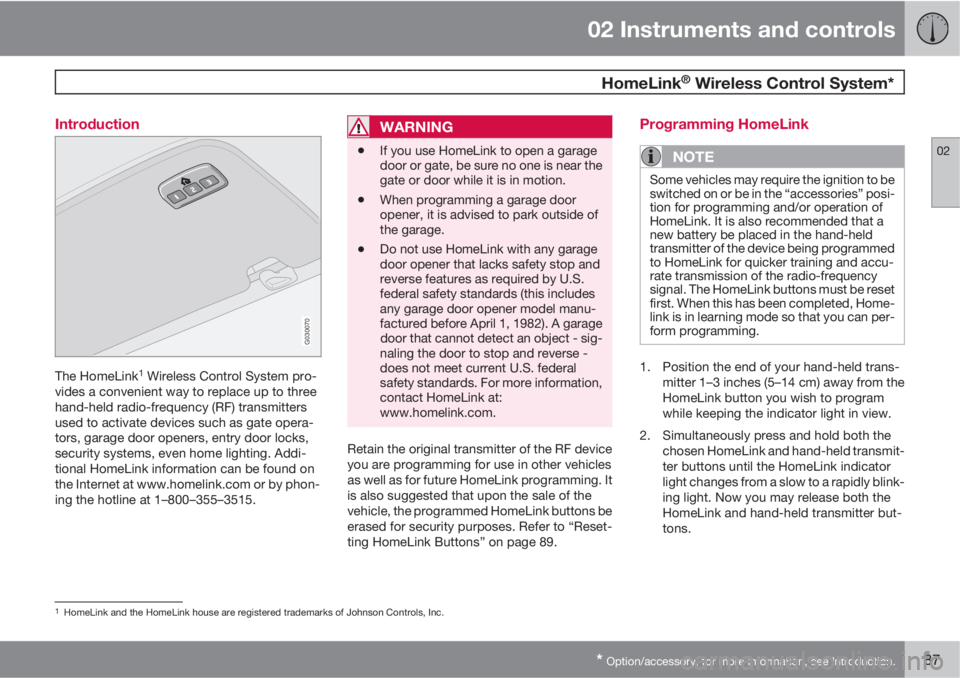
G030070
The HomeLink1 Wireless Control System pro-
vides a convenient way to replace up to three
hand-held radio-frequency (RF) transmitters
used to activate devices such as gate opera-
tors, garage door openers, entry door locks,
security systems, even home lighting. Addi-
tional HomeLink information can be found on
the Internet at www.homelink.com or by phon-
ing the hotline at 1–800–355–3515.
WARNING
•If you use HomeLink to open a garage
door or gate, be sure no one is near the
gate or door while it is in motion.
•When programming a garage door
opener, it is advised to park outside of
the garage.
•Do not use HomeLink with any garage
door opener that lacks safety stop and
reverse features as required by U.S.
federal safety standards (this includes
any garage door opener model manu-
factured before April 1, 1982). A garage
door that cannot detect an object - sig-
naling the door to stop and reverse -
does not meet current U.S. federal
safety standards. For more information,
contact HomeLink at:
www.homelink.com.
Retain the original transmitter of the RF device
you are programming for use in other vehicles
as well as for future HomeLink programming. It
is also suggested that upon the sale of the
vehicle, the programmed HomeLink buttons be
erased for security purposes. Refer to “Reset-
ting HomeLink Buttons” on page 89.
Programming HomeLink
NOTE
Some vehicles may require the ignition to be
switched on or be in the “accessories” posi-
tion for programming and/or operation of
HomeLink. It is also recommended that a
new battery be placed in the hand-held
transmitter of the device being programmed
to HomeLink for quicker training and accu-
rate transmission of the radio-frequency
signal. The HomeLink buttons must be reset
first. When this has been completed, Home-
link is in learning mode so that you can per-
form programming.
1. Position the end of your hand-held trans-
mitter 1–3 inches (5–14 cm) away from the
HomeLink button you wish to program
while keeping the indicator light in view.
2. Simultaneously press and hold both the
chosen HomeLink and hand-held transmit-
ter buttons until the HomeLink indicator
light changes from a slow to a rapidly blink-
ing light. Now you may release both the
HomeLink and hand-held transmitter but-
tons.
1HomeLink and the HomeLink house are registered trademarks of Johnson Controls, Inc.
Page 90 of 300
02 Instruments and controls
HomeLink® Wireless Control System*
02
88* Option/accessory, for more information, see Introduction.
NOTE
Some devices may require you to replace
this Programming Step 2 with procedures
noted in the “Gate Operator / Canadian Pro-
gramming” section. If the HomeLink indica-
tor light does not change to a rapidly blink-
ing light after performing these steps, con-
tact HomeLink at www.homelink.com or by
phoning the hotline at 1–800–355–3515.
3.
Firmly press, hold for five seconds and
release the programmed HomeLink but-
ton up to two separate times to activate the
door. If the door does not activate, press
and hold the just-trained HomeLink button
and observe the indicator light.
•If the indicator light stays on con-
stantly, programming is complete
and your device should activate when
the HomeLink button is pressed and
released.
•If the indicator light blinks rapidly for
two seconds and then turns to a con-
stant light continue with “Program-
ming” steps 4-6 to complete the pro-
gramming of a rolling code equipped
device (most commonly a garage door
opener).
4. At the garage door opener receiver (motor-
head unit) in the garage, locate the “learn”or “smart” button. This can usually be
found where the hanging antenna wire is
attached to the motor-head unit.
5. Firmly press and release the “learn” or
“smart” button. (The name and color of the
button may vary by manufacturer.) There
are 30 seconds to initiate step 6.
6. Return to the vehicle and firmly press, hold
for two seconds and release the pro-
grammed HomeLink button. Repeat the
“press/hold/release” sequence a second
time, and, depending on the brand of the
garage door opener (or other rolling code
equipped device), repeat this sequence a
third time to complete the programming
process.
HomeLink should now activate your rolling
code equipped device.
Gate Operator/Canadian ProgrammingCanadian radio-frequency laws require trans-
mitter signals to “time-out” (or quit) after sev-
eral seconds of transmission – which may not
be long enough for HomeLink to pick up the
signal during programming. Similar to this
Canadian law, some U.S. gate operators are
designed to “time-out” in the same manner.
If you live in Canada or you are having difficul-
ties programming a gate operator or garage
door opener by using the “Programming” pro-cedures, replace “Programming HomeLink”
step 2 with the following:
•Continue to press and hold the HomeLink
button while you press and release -
every two seconds (“cycle”) your hand-
held transmitter until the HomeLink indica-
tor light changes from a slow to a rapidly
blinking light. Now you may release both
the HomeLink and hand-held transmitter
buttons.
Proceed with “Programming” step 3 to com-
plete.
Using HomeLink
To operate, simply press and hold the pro-
grammed HomeLink button until the trained
device begins to operate (this may take several
seconds). Activation will now occur for the
trained device (i.e., garage door opener, gate
operator, security system, entry door lock,
home/office lighting, etc.). For convenience,
the hand-held transmitter of the device may
also be used at any time. In the event that there
are still programming difficulties or questions,
contact HomeLink at: www.homelink.com or
by phoning the hotline at 1–800–355–3515.
Page 133 of 300

05 Locks and alarm
Keyless drive*
05
* Option/accessory, for more information, see Introduction.131 Keyless locking and unlocking
G007577
Range of the keyless drive remote key–5 ft
(1.5 meters)
This system makes it possible to unlock and
lock the vehicle without having to use the
remote key. It is only necessary to have a key-
less drive remote key in your possession to
operate the central locking system.
NOTE
The buttons on the keyless drive remote key
can also be used to lock and unlock the
vehicle, see page 127 for more information.
Both of the remote keys provided with the vehi-
cle have the keyless function, and additional
remotes can be ordered. The system can
accommodate up to six keyless drive remote
keys.
NOTE
The number of doors that are unlocked at
the same time can be set in the Personal
settings menu, see page 84 for additional
information.
Unlocking the vehicle
•A keyless drive remote key must be on the
same side of the vehicle as the door to be
opened, and be within 5 feet (1.5 meters)
of the lock or the liftgate opening control
(see the shaded areas in the illustration).
•Pull a door handle to unlock and open the
door or press the liftgate opening control
on the liftgate.
•See page 152 for information on starting a
vehicle equipped with keyless drive.
Locking the vehicle
G020033
Keyless drive lock button
The doors and the liftgate can be locked by
pressing the lock button in any of the outside
door handles.
NOTE
•If one or more doors and/or the liftgate
is not fully closed when the lock button
is pressed, the door(s) or liftgate will not
be locked.
•On keyless drive vehicles with an auto-
matic transmission, the gear selector
must be in the Park (P) position and the
ignition must be switched off before the
doors/liftgate can be locked.
Page 142 of 300
140* Option/accessory, for more information, see Introduction.
General information............................................................................... 142
Fuel requirements................................................................................. 146
Ignition switch....................................................................................... 149
Starting the vehicle............................................................................... 150
Starting the vehicle with keyless drive*................................................. 152
Manual transmission, 6-speed*............................................................ 154
Automatic transmission........................................................................ 155
Shiftlock override.................................................................................. 158
Brake system........................................................................................ 159
Parking brake........................................................................................ 162
Stability system..................................................................................... 163
Towing.................................................................................................. 165
Jump starting........................................................................................ 168
Transporting loads................................................................................ 169
Blind Spot Information System (BLIS)*................................................. 170
Rear park assist*................................................................................... 174
Page 144 of 300
06 Starting and driving
General information
06
142
Economical driving conserves natural
resources
Better driving economy may be obtained by
thinking ahead, avoiding rapid starts and stops
and adjusting the speed of your vehicle to
immediate traffic conditions.
Observe the following rules:
•Bring the engine to normal operating tem-
perature as soon as possible by driving
with a light foot on the accelerator pedal for
the first few minutes of operation. A cold
engine uses more fuel and is subject to
increased wear.
•Whenever possible, avoid using the vehicle
for driving short distances. This does not
allow the engine to reach normal operating
temperature.
•Drive carefully and avoid rapid acceleration
and hard braking.
•Use the transmission's Drive (D) position
as often as possible and avoid using kick-
down.
•On models with a manual transmission,
use the highest gear possible, depending
on the vehicle's speed.
•Do not exceed posted speed limits.
•Avoid carrying unnecessary items (extra
load) in the vehicle.
•Maintain correct tire pressure. Check tire
pressure regularly (when tires are cold).
•Remove snow tires when threat of snow or
ice has ended.
•Note that roof racks, ski racks, etc,
increase air resistance and also fuel con-
sumption.
•At highway driving speeds, fuel consump-
tion will be lower with the air conditioning
on and the windows closed than with the
air conditioning off and the windows open.
•Using the onboard trip computer's fuel
consumption modes can help you learn
how to drive more economically.
Other factors that decrease gas mileage
are:
•Dirty air cleaner
•Dirty engine oil and clogged oil filter
•Dragging brakes
•Incorrect front end alignment
Some of the above mentioned items and others
are checked at the standard maintenance
intervals.
WARNING
Driving with the liftgate open: Driving with
the liftgate open could lead to poisonous
exhaust gases entering the passenger com-
partment. If the liftgate must be kept open
for any reason, proceed as follows:
1. Close the windows.
2. Set the ventilation system control to air
flow to floor, windshield and side win-
dows and the blower control to its high-
est setting.
Weight distribution affects handling
At the specified curb weight your vehicle has a
tendency to understeer, which means that the
steering wheel has to be turned more than
might seem appropriate for the curvature of a
bend. This ensures good stability and reduces
the risk of rear wheel skid. Remember that
these properties can alter with the vehicle load.
The heavier the load in the cargo area, the less
the tendency to understeer.
Page 146 of 300
06 Starting and driving
General information
06
144
•Volvo recommends the use of snow tires
on all four wheels for winter driving – see
the chapter "Wheels and tires."
•To prevent the washer fluid reservoir from
freezing, add washer solvents containing
antifreeze (see page 220 for the location of
the washer fluid reservoir). This is impor-
tant since dirt is often splashed on the
windshield during winter driving, requiring
the frequent use of the washers and wip-
ers. Volvo Washer Solvent should be dilu-
ted as follows: Down to 14 °F (–10 °C):
1 part washer solvent and 4 parts water
Down to 5 °F (–15 °C): 1 part washer sol-
vent and 3 parts water Down to 0 °F
(–18 °C): 1 part washer solvent and 2 parts
water Down to –18 °F (–28 °C): 1 part
washer solvent and 1 part water.
•Use Volvo Teflon Lock Spray in the locks.
NOTE
Avoid using de-icing sprays as they can
cause damage to the locks.
Conserving electrical current
Keep the following in mind to help minimize
battery drain:
•When the engine is not running, avoid turn-
ing the ignition key to position II. Many
electrical systems (the audio system, the
optional navigation system, power win-
dows, etc) will function with the ignition key
in position I. This position reduces drain on
the battery.
•Please keep in mind that using systems,
accessories, etc that consume a great deal
of current when the engine is not running
could result in the battery being completely
drained. Driving or having the engine run-
ning for approximately 15 minutes will help
keep the battery charged.
•The optional 12 volt socket in the cargo
area (certain models only) provides electri-
cal current even with the ignition switched
off, which drains the battery.
NOTE
•If the ignition is switched on, a warning
message will be displayed in the text
window in the instrument panel when
the battery charge is low.
•An energy conserving function
designed into the vehicle's electrical
system will switch off certain functions
or reduce the load on the battery by,
e.g., reducing the audio system's vol-
ume.
Before a long distance trip
It is always worthwhile to have your vehicle
checked at a trained and qualified Volvo serv-
ice technician before driving long distances.
Your trained and qualified Volvo service tech-
nician will also be able to supply you with
bulbs, fuses, spark plugs and wiper blades for
your use in the event that problems occur.
As a minimum, the following items should be
checked before any long trip:
•Check that engine runs smoothly and that
fuel consumption is normal.
•Check for fuel, oil, and fluid leakage.
•Have the transmission oil level checked1.
•Check condition of drive belts.
1To prevent injury from contact with hot surfaces, do not inspect your vehicle's transmission fluid yourself. Have your vehicle's transmission fluid level inspected by a qualified Volvo service technician.