engine VOLVO C70 2001 Owner's Manual
[x] Cancel search | Manufacturer: VOLVO, Model Year: 2001, Model line: C70, Model: VOLVO C70 2001Pages: 88, PDF Size: 2.07 MB
Page 55 of 88

(thousand km)(12)(24)(36) (48)(60) (72)(84)(96)(108) (120) (132)(144)
EMISSION SYSTEM MAINTENANCE
Engine
Fuel line filter
1
PCV nipple (orifice)/hoses, clean I I
Battery (check charge and electrolyte level) II II II I I I II I
Brakes
Inspect brake pads, replace components as necessary I II II I I I II I
Brake fluid level
2 - check
I I I I I I
Steering/suspension
Tires
3, check pressure, wear and condition I
I II II I I I II I
Check power steering fluid level I I I I I I
Body
Power antenna (clean) L L L L L L
Trunk/hood, hinges and latches L L L L
Cabin air filter (see page 109)
R R R R R R
1) Replace at 105,000 miles (168,000 km)
2) Brake fluid should be changed at owner request every second year or 30,000 miles (48,000 km). The fluid
should be replaced once a year or every 15,000 miles (24,000 km) when driving under extremely hard
conditions (mountain driving, etc.).
3) Rotate tires at owner request.
The following items should be checked weekly by the driver (it takes only a few minutes):
Engine oil level, brake fluid level, radiator coolant level, operation of all lights, horns, windshield wipers, tire
pressure (all five tires), windshield washer fluid level
The following should also be carried out at regular intervals:
Washing (check all drain holes), polishing, cleaning
pg. 108 Servicing
Hoisting the car
If a garage jack is used to lift the car, the two jack attachments points should be used. They are specially reinforced to
bear the weight of the car. A garage jack can also be placed under the front of the engine support frame and under the
reinforced plate in the spare wheel well. Take care not to damage the splash guard under the engine. Ensure that the
jack is positioned so that the car cannot slide off it. Always use axle stands or similar structures.
ProCarManuals.com
Page 56 of 88

If a twopost hoist is used to lift the car, the front lift arm pads should be positioned under the rear engine frame
mounts. The rear lift arm pads should be positioned under the rear supporting arm bracket.
CAUTION: Certain models have reduced ground clearance due to the design of the front spoiler. Please observe
caution when driving the car onto a garage hoist.
pg. 109 Servicing
Air cleaner
Replace the air cleaner cartridge with a new one every 30,000 miles (48,000 km). The cartridge should be replaced
more often when driving under dirty and dusty conditions. The filter cannot be cleaned and therefore should always be
replaced with a new one.
Timing belt
For proper functioning of the vehicle and its emission control systems, the timing belt and tensioner must be replaced
every 105,000 miles (168,000 km). Engine damage will occur if the belt fails.
Fuel system cap, tank and lines and connections
The effectiveness of the fuel system to contain hydrocarbons is dependent largely on a leakfree system. Check for
proper sealing of the fuel filler cap which contains "O" ring type seals.
NOTE: If the fuel filler cap is not closed tightly or if the engine is running when the car is refueled, the Malfunction
Indicator Lamp ("Check Engine") may indicate a fault. However, your vehicle's performance will not be affected. Use
only Volvo original or approved fuel filler caps.
Fuel (line) filter
For proper functioning of the vehicle and its emission control systems, the fuel line filter should be replaced at 105,000
miles (168,000 km). The filter is replaced as one complete unit. Replace more frequently if contaminated fuel is
introduced into the tank (or if there is reason to suspect that this has occurred).
PCV system
The orifice nipple in the intake manifold and the filter at the end of the PCV hose in the air cleaner should be
ProCarManuals.com
Page 57 of 88

inspected at 60,000 miles (96,000 km) and thereafter, at 30,000 mile (48,000 km) intervals.
Cabin air filter
Replace the cabin air filter with a new one at 15,000 mile (24,000 km) intervals. Volvo recommends replacing the
filter more often if the car is driven under dirty and dusty conditions. The filter cannot be cleaned and therefore should
always be replaced with a new one.
pg. 110 Fuel/emissions systems
Fuel system
The fuel system is allelectronic and is microprocessorcontrolled. It can continually compensate for variation in engine
load, speed and temperature to give the best economy and power. A mass air flow sensor measures the inducted air. In
this way the system can make instantaneous adjustments for changes in air temperature or density, thus always
assuring the best economy with the lowest possible exhaust emissions.
Heated oxygen sensor
This is an emission control system designed to reduce emissions and improve fuel economy. The heated oxygen sensor
monitors the composition of the exhaust gases leaving the engine. The exhaust gas analysis is fed into an electronic
module. This adjusts the airfuel ratio to provide optimum conditions for combustion and efficient reduction of the three
major pollutants (hydrocarbons, carbon monoxide and oxides of nitrogen (NOx) by a threeway catalytic converter.
Crankcase ventilation
The engine is provided with positive crankcase ventilation which prevents crankcase gases from being released into the
atmosphere. Instead, the crankcase gases are admitted to the intake manifold and cylinders.
Evaporative control system
The car is equipped with an evaporative control system which prevents gasoline vapor from being released into the
atmosphere.
The system consists of a fuel tank with filler pipe and cap, a rollover valve, a Fill Limit Vent Valve (FLVV), vapor
vent lines, a charcoal canister, a purge line, a purge control valve and engine connections .
In addition, there is a pressure sensor connected to the fuel tank and a filter -protected Canister Close Valve (CCV) on
the atmospheric side of the canister, for system diagnosis.
The gasoline vapor is channeled through the rollover valve and the FLVV via the vapor vent lines into the charcoal
ProCarManuals.com
Page 58 of 88

canister, where it is stored. When the engine is started, the gasoline vapor is drawn from the charcoal canister to the
engine's air intake system and into the combustion process.
NOTE:
· If the fuel filler cap is not closed tightly or if the engine is running when the car is refueled, the Malfunction Indicator
Lamp may indicate a fault.
· During a transitional period, a small number of service stations may still have fuel nozzles that are not compatible
with the fuel filler neck on cars equipped with the evaporative control system (ORVR) mandated by the U.S.
Environmental Protection Agency and the California Air Resources Board. If you experience difficulties in refueling
your vehicle, please ask the gas station attendant for assistance.
CAUTION:
Fuel must not be siphoned from the fuel tank. This will damage the Evaporative control system.
pg. 111 Lubrication
No.Lubrication point lubricant
1 Hood lock and latch Oil
2 Door stop and hinges Oil
3 Sun roof wind deflector (visible when sun roof is open) Oil, low temperature grease
4 Door lock catch plate Oil
5 Power antenna WD 40 or similar
6 Locks Volvo teflon lock spray
7 Trunk lock catch plate Low temperature grease
8 Front seat side rail and latch Oil
To avoid rattles and unnecessary wear, the body should be lubricated at regular service intervals. This should be done
by an authorized Volvo retailer.
ProCarManuals.com
Page 60 of 88

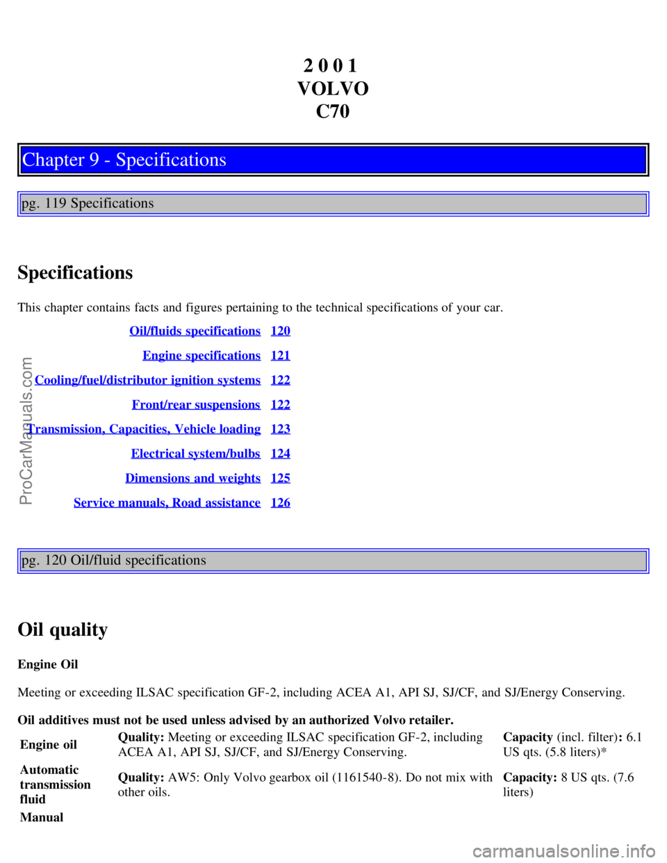
2 0 0 1
VOLVO C70
Chapter 9 - Specifications
pg. 119 Specifications
Specifications
This chapter contains facts and figures pertaining to the technical specifications of your car. Oil/fluids specifications
120
Engine specifications121
Cooling/fuel/distributor ignition systems122
Front/rear suspensions122
Transmission, Capacities, Vehicle loading123
Electrical system/bulbs124
Dimensions and weights125
Service manuals, Road assistance126
pg. 120 Oil/fluid specifications
Oil quality
Engine Oil
Meeting or exceeding ILSAC specification GF-2, including ACEA A1, API SJ, SJ/CF, and SJ/Energy Conserving.
Oil additives must not be used unless advised by an authorized Volvo retailer.
Engine oil Quality:
Meeting or exceeding ILSAC specification GF-2, including
ACEA A1, API SJ, SJ/CF, and SJ/Energy Conserving. Capacity (incl. filter)
: 6.1
US qts. (5.8 liters)*
Automatic
transmission
fluid Quality:
AW5: Only Volvo gearbox oil (1161540-8). Do not mix with
other oils. Capacity:
8 US qts. (7.6
liters)
Manual
ProCarManuals.com
Page 61 of 88

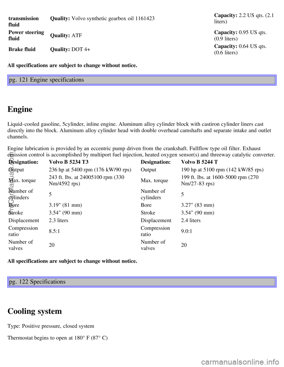
transmission
fluidQuality:
Volvo synthetic gearbox oil 1161423Capacity: 2.2 US qts. (2.1
liters)
Power steering
fluid Quality:
ATF Capacity:
0.95 US qts.
(0.9 liters)
Brake fluid Quality: DOT 4+ Capacity:
0.64 US qts.
(0.6 liters)
All specifications are subject to change without notice.
pg. 121 Engine specifications
Engine
Liquid-cooled gasoline, 5cylinder, inline engine. Aluminum alloy cylinder block with castiron cylinder liners cast
directly into the block. Aluminum alloy cylinder head with double overhead camshafts and separate intake and outlet
channels.
Engine lubrication is provided by an eccentric pump driven from the crankshaft. Fullflow type oil filter. Exhaust
emission control is accomplished by multiport fuel injection, heated oxygen sensor(s) and threeway catalytic converter.
Designation: Volvo B 5234 T3 Designation:Volvo B 5244 T
Output 236 hp at 5400 rpm (176 kW/90 rps) Output190 hp at 5100 rpm (142 kW/85 rps)
Max. torque 243 ft. lbs. at 24005100 rpm (330
Nm/4592 rps) Max. torque199 ft. lbs. at 1600-5000 rpm (270
Nm/27-83 rps)
Number of
cylinders 5 Number of
cylinders5
Bore 3.19" (81 mm) Bore3.27" (83 mm)
Stroke 3.54" (90 mm) Stroke3.54" (90 mm)
Displacement 2.3 liters Displacement2.4 liters
Compression
ratio 8.5:1 Compression
ratio9.0:1
Number of
valves 20 Number of
valves20
All specifications are subject to change without notice.
pg. 122 Specifications
Cooling system
Type: Positive pressure, closed system
Thermostat begins to open at 180° F (87° C)
ProCarManuals.com
Page 62 of 88

Coolant: Volvo original coolant/antifreeze
Capacity: 7.4 US qts. (7.0 liters)
Fuel system
The engine is equipped with a multiport fuel injection system.
Distributor ignition system
Firing order:12453
Distributor ignition setting: Not adjustable
Spark plugs: Champion RC8PYP (or equivalent)
Spark plug gap: 0.03" (0.75 mm)
Tightening torque: 18.4 ft. lbs. +/ 3.7 ft. lbs. (25 Nm +/ 5 Nm)
WARNING!
The distributor ignition system operates at very high voltages. Special safety precautions must be followed to
prevent injury. Always turn the ignition off when:
· Replacing distributor ignition components e.g. plugs, coil, etc.
· Do not touch any part of the distributor ignition system while the engine is running. This may result in unintended
movements and body injury.
Replacing spark plugs
The spark plugs should be changed every 30,000 miles (48,000 km). However, city driving or fast highway driving
may necessitate changing after 15,000 miles (24,000 km) of driving. When installing new plugs, be sure to fit the right
type and use correct torque, see "Specifications". When changing the plugs, check that the suppressor connectors are in
good condition. Cracked or damaged connectors should be replaced. When changing the spark plugs, clean the
terminals and the rubber seals.
Front suspension
Spring strut suspension with integrated shock absorbers and control arms linked to the support frame. Powerassisted
rack and pinion steering. Safety type steering column.
The alignment specifications apply to an unladen car but include fuel, coolant and spare wheel.
Toe-in measured on the wheel rims: 2.4 mm +/ 0.7 mm
Toe-in measured on tire sides: 2.9 +/ 0.9 mm
Rear suspension
Deltalink individual rear wheel suspension with longitudinal support arms, double link arms and track rods.
Toe-in measured on the tire sides: 4° +/ 10°
ProCarManuals.com
Page 63 of 88

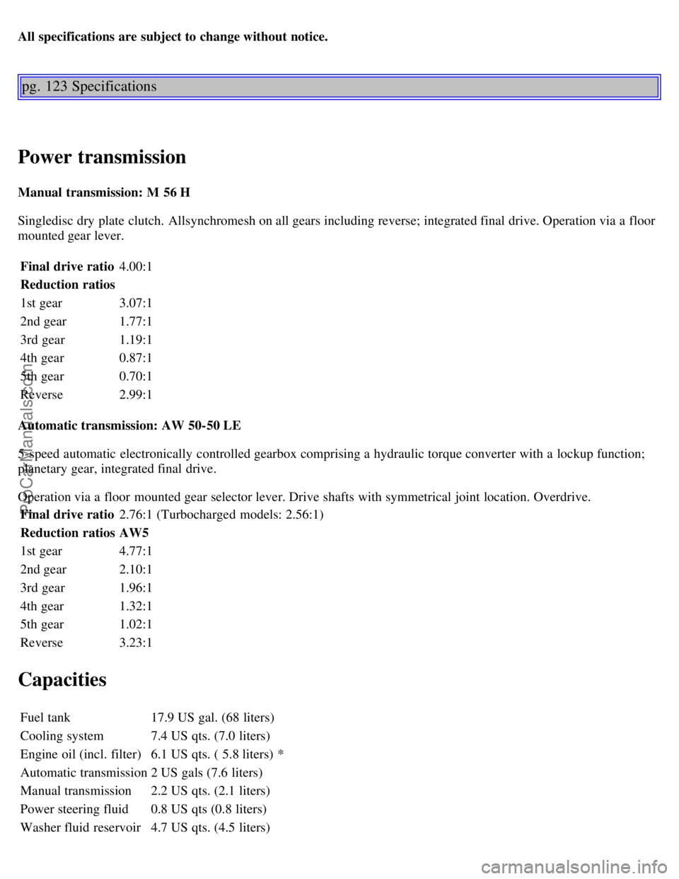
All specifications are subject to change without notice.
pg. 123 Specifications
Power transmission
Manual transmission: M 56 H
Singledisc dry plate clutch. Allsynchromesh on all gears including reverse; integrated final drive. Operation via a floor
mounted gear lever.Final drive ratio 4.00:1
Reduction ratios
1st gear 3.07:1
2nd gear 1.77:1
3rd gear 1.19:1
4th gear 0.87:1
5th gear 0.70:1
Reverse 2.99:1
Automatic transmission: AW 50-50 LE
5-speed automatic electronically controlled gearbox comprising a hydraulic torque converter with a lockup function;
planetary gear, integrated final drive.
Operation via a floor mounted gear selector lever. Drive shafts with symmetrical joint location. Overdrive. Final drive ratio 2.76:1 (Turbocharged models: 2.56:1)
Reduction ratios AW5
1st gear 4.77:1
2nd gear 2.10:1
3rd gear 1.96:1
4th gear 1.32:1
5th gear 1.02:1
Reverse 3.23:1
Capacities
Fuel tank 17.9 US gal. (68 liters)
Cooling system 7.4 US qts. (7.0 liters)
Engine oil (incl. filter) 6.1 US qts. ( 5.8 liters) *
Automatic transmission 2 US gals (7.6 liters)
Manual transmission 2.2 US qts. (2.1 liters)
Power steering fluid 0.8 US qts (0.8 liters)
Washer fluid reservoir 4.7 US qts. (4.5 liters)
ProCarManuals.com
Page 64 of 88

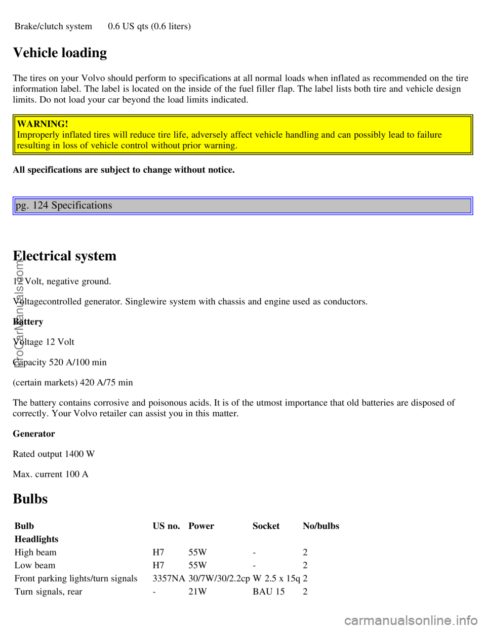
Brake/clutch system0.6 US qts (0.6 liters)
Vehicle loading
The tires on your Volvo should perform to specifications at all normal loads when inflated as recommended on the tire
information label. The label is located on the inside of the fuel filler flap. The label lists both tire and vehicle design
limits. Do not load your car beyond the load limits indicated.
WARNING!
Improperly inflated tires will reduce tire life, adversely affect vehicle handling and can possibly lead to failure
resulting in loss of vehicle control without prior warning.
All specifications are subject to change without notice.
pg. 124 Specifications
Electrical system
12 Volt, negative ground.
Voltagecontrolled generator. Singlewire system with chassis and engine used as conductors.
Battery
Voltage 12 Volt
Capacity 520 A/100 min
(certain markets) 420 A/75 min
The battery contains corrosive and poisonous acids. It is of the utmost importance that old batteries are disposed of
correctly. Your Volvo retailer can assist you in this matter.
Generator
Rated output 1400 W
Max. current 100 A
Bulbs
Bulb US no.Power SocketNo/bulbs
Headlights
High beam H755W -2
Low beam H755W -2
Front parking lights/turn signals 3357NA30/7W/30/2.2cp W 2.5 x 15q2
Turn signals, rear -21W BAU 152
ProCarManuals.com
Page 77 of 88

The programmed button on your HomeLink® Universal Transceiver should now operate your garage door opener. The
original hand -held transmitter can also be used, as desired, to operate the garage door.
Operating the HomeLink® Universal Transceiver Once programmed, the HomeLink® Universal Transceiver can
be used in place of your hand -held transmitters.
To operate, the key must be turned to the "accessory" position (II) or the engine must be running. Press the
programmed HomeLink® button to activate the garage door, driveway gate, security lighting, home security system,
etc.
Your original hand -held transmitters may, of course, be used at any time.
Erasing programmed buttons
Individual buttons cannot be erased. To erase all three programmed buttons:
1. 1. Turn the ignition key to the "accessory" position (II).
2. Hold down the two outside buttons on the HomeLink® Universal Transceiver for about 20 seconds, until
HomeLink® 's indicator light begins to flash.
3. Release both buttons.
The HomeLink® buttons can be reprogrammed using the procedures described on the previous page.
(HomeLink® information is continued on the next page)
pg. 186 HomeLink® Universal Transceiver (option)
Reprogramming a single HomeLink® button
1. Press and hold the desired HomeLink® button. Do not release the button until step 3 has been completed.
2. When the indicator light begins to flash slowly (after approximately 20 seconds), position the hand -held transmitter
2 to 5 in. (5 to 12 cm) away from the HomeLink® surface.
3. Press and hold the hand -held transmitter button.
The HomeLink® indicator light will begin to flash, first slowly then rapidly. When the indicator light flashes rapidly,
release both buttons.
The previously programmed device has now been erased and the new device can be activated by pressing the
HomeLink® button that has just been programmed. This procedure will not affect any other programmed HomeLink®
buttons.
NOTE:
· Retain the original transmitter(s) for future programming procedures (i.e., if you purchase a new car).
· It is also suggested that if you sell your car, the programmed channels on the HomeLink® Universal Transceiver be
erased for security purposes.
ProCarManuals.com