clock VOLVO C70 2002 Owners Manual
[x] Cancel search | Manufacturer: VOLVO, Model Year: 2002, Model line: C70, Model: VOLVO C70 2002Pages: 99, PDF Size: 2.56 MB
Page 15 of 99

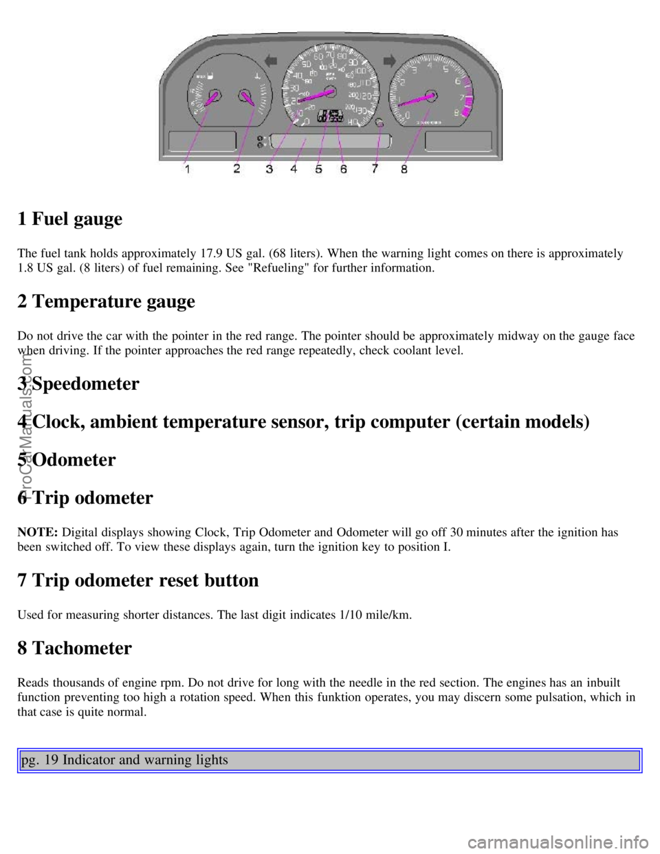
1 Fuel gauge
The fuel tank holds approximately 17.9 US gal. (68 liters). When the warning light comes on there is approximately
1.8 US gal. (8 liters) of fuel remaining. See "Refueling" for further information.
2 Temperature gauge
Do not drive the car with the pointer in the red range. The pointer should be approximately midway on the gauge face
when driving. If the pointer approaches the red range repeatedly, check coolant level.
3 Speedometer
4 Clock, ambient temperature sensor, trip computer (certain models)
5 Odometer
6 Trip odometer
NOTE: Digital displays showing Clock, Trip Odometer and Odometer will go off 30 minutes after the ignition has
been switched off. To view these displays again, turn the ignition key to position I.
7 Trip odometer reset button
Used for measuring shorter distances. The last digit indicates 1/10 mile/km.
8 Tachometer
Reads thousands of engine rpm. Do not drive for long with the needle in the red section. The engines has an inbuilt
function preventing too high a rotation speed. When this funktion operates, you may discern some pulsation, which in
that case is quite normal.
pg. 19 Indicator and warning lights
ProCarManuals.com
Page 35 of 99

Manually operated passenger's seat (certain models)
1 Height adjustment
The front section of the seat can be adjusted to 7 different height settings (lever A) and the rear section can be adjusted
to 9 different height settings (lever B).
2 Forward-rearward seat adjustment
Pull the bar upward, then slide the seat forward or rearward to the desired position. Make sure that the seat is properly
secured when you release the bar.
3 Backrest tilt
Rotate the control counterclockwise to tilt the backrest rearward and clockwise to tilt the
backrest forward.
4 Lumbar support
5 Strap for controlling front seat for rear seat passengers (see following page)
Contents | Top of Page
ProCarManuals.com
Page 39 of 99

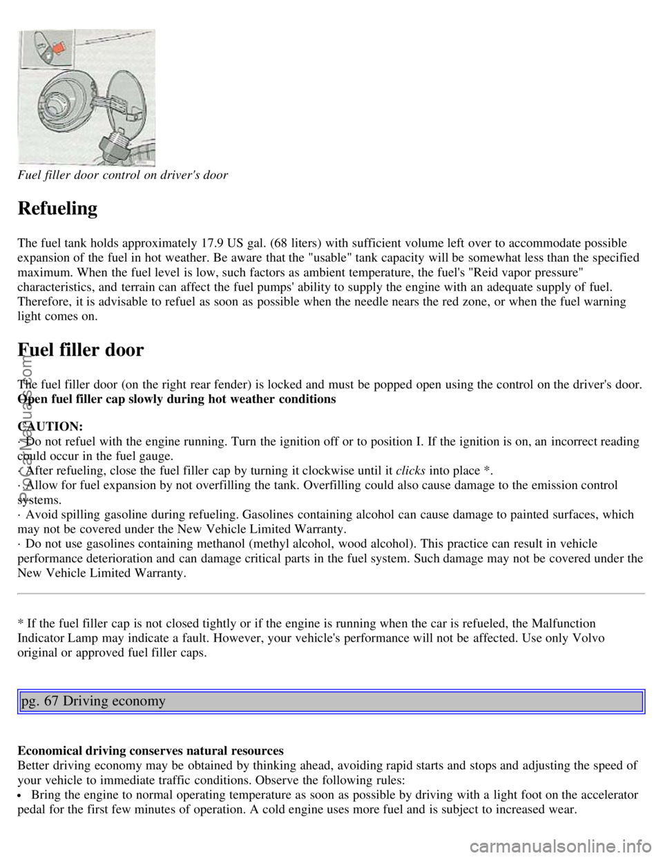
Fuel filler door control on driver's door
Refueling
The fuel tank holds approximately 17.9 US gal. (68 liters) with sufficient volume left over to accommodate possible
expansion of the fuel in hot weather. Be aware that the "usable" tank capacity will be somewhat less than the specified
maximum. When the fuel level is low, such factors as ambient temperature, the fuel's "Reid vapor pressure"
characteristics, and terrain can affect the fuel pumps' ability to supply the engine with an adequate supply of fuel.
Therefore, it is advisable to refuel as soon as possible when the needle nears the red zone, or when the fuel warning
light comes on.
Fuel filler door
The fuel filler door (on the right rear fender) is locked and must be popped open using the control on the driver's door.
Open fuel filler cap slowly during hot weather conditions
CAUTION:
· Do not refuel with the engine running. Turn the ignition off or to position I. If the ignition is on, an incorrect reading
could occur in the fuel gauge.
· After refueling, close the fuel filler cap by turning it clockwise until it clicks into place *.
· Allow for fuel expansion by not overfilling the tank. Overfilling could also cause damage to the emission control
systems.
· Avoid spilling gasoline during refueling. Gasolines containing alcohol can cause damage to painted surfaces, which
may not be covered under the New Vehicle Limited Warranty.
· Do not use gasolines containing methanol (methyl alcohol, wood alcohol). This practice can result in vehicle
performance deterioration and can damage critical parts in the fuel system. Such damage may not be covered under the
New Vehicle Limited Warranty.
* If the fuel filler cap is not closed tightly or if the engine is running when the car is refueled, the Malfunction
Indicator Lamp may indicate a fault. However, your vehicle's performance will not be affected. Use only Volvo
original or approved fuel filler caps.
pg. 67 Driving economy
Economical driving conserves natural resources
Better driving economy may be obtained by thinking ahead, avoiding rapid starts and stops and adjusting the speed of
your vehicle to immediate traffic conditions. Observe the following rules:
Bring the engine to normal operating temperature as soon as possible by driving with a light foot on the accelerator
pedal for the first few minutes of operation. A cold engine uses more fuel and is subject to increased wear.
ProCarManuals.com
Page 50 of 99

2 0 0 2
VOLVO
C70 Coupe & Convertible
Chapter 6 - In case of an emergency
pg. 89 In case of an emergency
Page
Wheel changing 90
Spare tire92
Replacing bulbs93
Replacing fuses99
Installation of accessories102
Replacing wiper blades103
In case of emergency105
pg. 90 Wheel changing
Loosen wheel bolts
Changing a wheel
The spare wheel is located under the carpet on the trunk floor. The jack and crank are secured in the wheel recess.
Engage the parking brake.
Put the gear selector in (P)ark (automatic) or in Reverse (manual).
With the car still on the ground, use the lug wrench to loosen the wheel bolts 1/2 1 turn. Turn the bolts
counterclockwise to loosen.
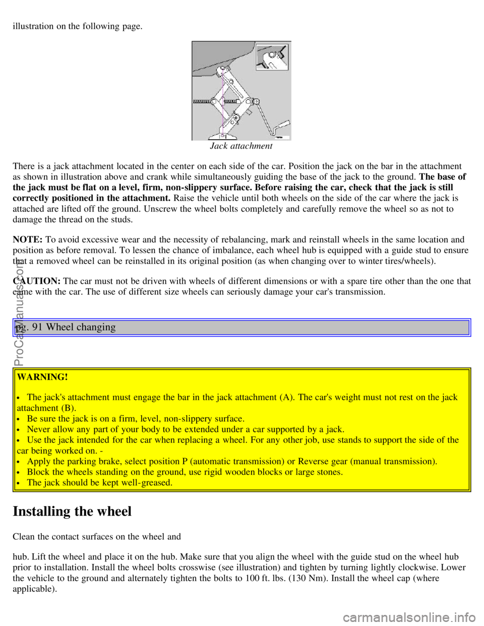
Fold out the crank handle on the jack by pressing the knob on the handle downward. To attach the jack, refer to the
ProCarManuals.com
Page 51 of 99

illustration on the following page.
Jack attachment
There is a jack attachment located in the center on each side of the car. Position the jack on the bar in the attachment
as shown in illustration above and crank while simultaneously guiding the base of the jack to the ground. The base of
the jack must be flat on a level, firm, non-slippery surface. Before raising the car, check that the jack is still
correctly positioned in the attachment. Raise the vehicle until both wheels on the side of the car where the jack is
attached are lifted off the ground. Unscrew the wheel bolts completely and carefully remove the wheel so as not to
damage the thread on the studs.
NOTE: To avoid excessive wear and the necessity of rebalancing, mark and reinstall wheels in the same location and
position as before removal. To lessen the chance of imbalance, each wheel hub is equipped with a guide stud to ensure
that a removed wheel can be reinstalled in its original position (as when changing over to winter tires/wheels).
CAUTION: The car must not be driven with wheels of different dimensions or with a spare tire other than the one that
came with the car. The use of different size wheels can seriously damage your car's transmission.
pg. 91 Wheel changing
WARNING!
The jack's attachment must engage the bar in the jack attachment (A). The car's weight must not rest on the jack
attachment (B).
Be sure the jack is on a firm, level, non-slippery surface.
Never allow any part of your body to be extended under a car supported by a jack.
Use the jack intended for the car when replacing a wheel. For any other job, use stands to support the side of the
car being worked on. -
Apply the parking brake, select position P (automatic transmission) or Reverse gear (manual transmission).
Block the wheels standing on the ground, use rigid wooden blocks or large stones.
The jack should be kept well-greased.
Installing the wheel
Clean the contact surfaces on the wheel and
hub. Lift the wheel and place it on the hub. Make sure that you align the wheel with the guide stud on the wheel hub
prior to installation. Install the wheel bolts crosswise (see illustration) and tighten by turning lightly clockwise. Lower
the vehicle to the ground and alternately tighten the bolts to 100 ft. lbs. (130 Nm). Install the wheel cap (where
applicable).
ProCarManuals.com
Page 53 of 99

Parking light/direction indicator
1. From the front of the car, use a screwdriver to press down on the silver catch (located in the space between the
inside of the fender and the headlight unit) to release the lamp housing from the front fender.
2. Turn the bulb holder 1/4 turn clockwise (viewed from the front) and withdraw it from the from the lamp housing.
Leave the connector with its wires in the bulb holder.
4. Remove the bulb from the holder by pulling it straight out.
5. Press a new bulb into the holder and reinstall the unit in the reverse order.
Side direction indicator
1. Slide the lens forward and pull out the rear edge.
2. Pull out the entire lens/bulb unit.
3. With the lens toward you, turn the bulb holder 1/4 turn (the wires should not be disconnected from the holder) and
pull out the bulb holder from the lens unit.
4. Pull the old bulb straight out and press a new one into place.
5. Replace the entire unit in the reverse order.
pg. 94 Replacing bulbs
ProCarManuals.com
Page 54 of 99

A - Low beam Bulbs (high and low beams) - H7 B - High beam
Low beam headlight bulb (A) replacement
1. Turn the plastic cover counterclockwise and remove it.
2. Press the wire catches on the retaining clamp (1 in inset illustration above) together and push out (2) to release the
bulb and connector from the headlight housing.
3. Pull the bulb out of the connector.
4. Insert a new bulb into the connector.
5. Reinsert the bulb and connector into the headlight housing. The guide lug must be up to ensure proper positioning.
6. Press the retaining clamp back into position.
7. Reinstall the plastic cover. The marking "Top" on the cover should be up when the cover is reinstalled.
High beam headlight bulb (B) replacement
1. Pull the catch on the lower edge of the cover upward and remove the plastic cover.
2. Press the wire catches on the retaining clamp (1 in inset illustration above) together and push out (2) to release the
bulb and connector from the headlight housing.
3. Pull the bulb out of the connector.
4. Insert a new bulb into the connector.
5. Reinsert the bulb and connector into the headlight housing. The guide lug must be up to ensure proper positioning.
6. Press the retaining clamp back into position.
7. Reinstall the plastic cover. Catch B should snap into position.
Caution! Do not touch the glass on halogen bulbs with your fingers. Grease, oil or any other impurities can be
carbonized onto the bulb and cause damage to the reflector.
Be sure to use bulbs of the correct type and voltage
pg.95 Replacing bulbs
ProCarManuals.com
Page 55 of 99

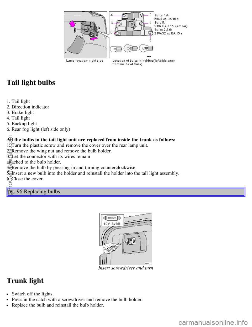
Tail light bulbs
1. Tail light
2. Direction indicator
3. Brake light
4. Tail light
5. Backup light
6. Rear fog light (left side only)
All the bulbs in the tail light unit are replaced from inside the trunk as follows:
1. Turn the plastic screw and remove the cover over the rear lamp unit.
2. Remove the wing nut and remove the bulb holder.
3. Let the connector with its wires remain
attached to the bulb holder.
4. Remove the bulb by pressing in and turning counterclockwise.
5. Insert a new bulb into the holder and reinstall the holder into the tail light assembly.
6. Close the cover.
pg. 96 Replacing bulbs
Insert screwdriver and turn
Trunk light
Switch off the lights.
Press in the catch with a screwdriver and remove the bulb holder.
Replace the bulb and reinstall the bulb holder.
ProCarManuals.com
Page 80 of 99

· the unit must be turned on
Make sure the headlights are turned off to help prevent battery drain (please refer to page 22
for information on turning
the headlights off).
Enter the code again once this time has elapsed.
pg. 140 Radio SC -813
A - On/off switch
Push the button to switch on the radio. Press the button slightly longer to turn the radio off.
B - Volume control
Turn the button clockwise to increase the volume. The volume control is electronic and has no end stop.
C - Waveband selector
The desired waveband is set by pressing one of the waveband selector buttons. The frequency and waveband is shown
on the display.
NOTE: There are two FM wavebands and one
AM waveband. This makes it possible to store 2 x 6 FM stations and 6 AM stations in memory.
D - Setting frequency selection
The radio can be used in most parts of the world by changing the frequency selection intervals as follows:
Depress and hold preset button 5 and turn the radio ON. "USA" will flash on the display.
Each time button 5 is pressed, the frequency selection will change from "USA" to "AUS", etc. When the correct
country name is displayed, wait 5 seconds and the radio will be ready for use.
E - Manual tuning
ProCarManuals.com
Page 83 of 99

A - Fader control
Adjust front/rear speaker balance by sliding the control up or down.
(UP to direct more sound to the front speakers, DOWN to direct more sound to the rear speakers).
The "detent" indicates "equalized" front /rear balance position.
B - Pause function
Press the "volume" knob to temporarily mute the sound. "PAUSE" is displayed.
C - Balance control
Pull out the "volume" knob and adjust the left/right balance by turning the knob counter- clockwise or clockwise.
D - Scan
Press this button to listen to each station for five seconds. Press it again to stop scanning. "Scan" will be displayed
during scanning.
E - Active sound control (ASC)
The ASC function automatically adjusts the volume level of the audio system according to driving speed.
To deactivate ASC depress the "ASC" button.
To activate ASC, depress the "ASC" button until "ASC" is displayed.
pg. 144 Cassette deck
A - Cassette slot
The cassette is inserted with the open side to the right (side 1 or A of the cassette upwards).
ProCarManuals.com