fuel cap VOLVO C70 2002 Owners Manual
[x] Cancel search | Manufacturer: VOLVO, Model Year: 2002, Model line: C70, Model: VOLVO C70 2002Pages: 99, PDF Size: 2.56 MB
Page 17 of 99
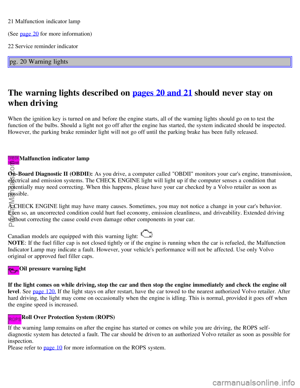
21 Malfunction indicator lamp
(See page 20
for more information)
22 Service reminder indicator
pg. 20 Warning lights
The warning lights described on pages 20 and 21 should never stay on
when driving
When the ignition key is turned on and before the engine starts, all of the warning lights should go on to test the
function of the bulbs. Should a light not go off after the engine has started, the system indicated should be inspected.
However, the parking brake reminder light will not go off until the parking brake has been fully released.
Malfunction indicator lamp
On-Board Diagnostic II (OBDII): As you drive, a computer called "OBDII" monitors your car's engine, transmission,
electrical and emission systems. The CHECK ENGINE light will light up if the computer senses a condition that
potentially may need correcting. When this happens, please have your car checked by a Volvo retailer as soon as
possible.
A CHECK ENGINE light may have many causes. Sometimes, you may not notice a change in your car's behavior.
Even so, an uncorrected condition could hurt fuel economy, emission cleanliness, and driveability. Extended driving
without correcting the cause could even damage other components in your car.
Canadian models are equipped with this warning light:
NOTE : If the fuel filler cap is not closed tightly or if the engine is running when the car is refueled, the Malfunction
Indicator Lamp may indicate a fault. However, your vehicle's performance will not be affected. Use only Volvo
original or approved fuel filler caps.
Oil pressure warning light
If the light comes on while driving, stop the car and then stop the engine immediately and check the engine oil
level . See page 120.
If the light stays on after restart, have the car towed to the nearest authorized Volvo retailer. After
hard driving, the light may come on occasionally when the engine is idling. This is normal, provided it goes off when
the engine speed is increased.
Roll Over Protection System (ROPS)
If the warning lamp remains on after the engine has started or comes on while you are driving, the ROPS self -
diagnostic system has detected a fault. The car should be driven to an authorized Volvo retailer as soon as possible for
inspection.
Please refer to page 10
for more information on the ROPS system.
ProCarManuals.com
Page 39 of 99
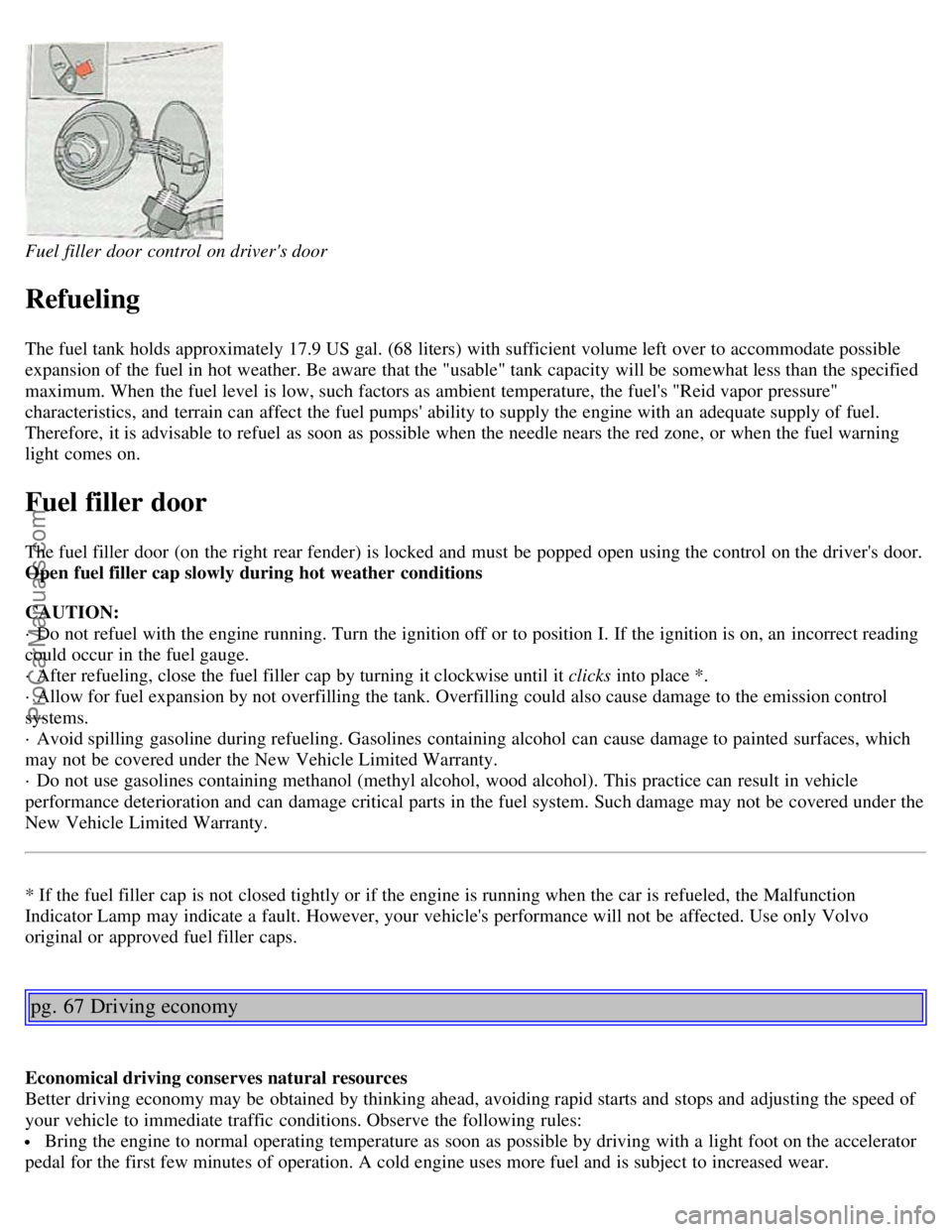
Fuel filler door control on driver's door
Refueling
The fuel tank holds approximately 17.9 US gal. (68 liters) with sufficient volume left over to accommodate possible
expansion of the fuel in hot weather. Be aware that the "usable" tank capacity will be somewhat less than the specified
maximum. When the fuel level is low, such factors as ambient temperature, the fuel's "Reid vapor pressure"
characteristics, and terrain can affect the fuel pumps' ability to supply the engine with an adequate supply of fuel.
Therefore, it is advisable to refuel as soon as possible when the needle nears the red zone, or when the fuel warning
light comes on.
Fuel filler door
The fuel filler door (on the right rear fender) is locked and must be popped open using the control on the driver's door.
Open fuel filler cap slowly during hot weather conditions
CAUTION:
· Do not refuel with the engine running. Turn the ignition off or to position I. If the ignition is on, an incorrect reading
could occur in the fuel gauge.
· After refueling, close the fuel filler cap by turning it clockwise until it clicks into place *.
· Allow for fuel expansion by not overfilling the tank. Overfilling could also cause damage to the emission control
systems.
· Avoid spilling gasoline during refueling. Gasolines containing alcohol can cause damage to painted surfaces, which
may not be covered under the New Vehicle Limited Warranty.
· Do not use gasolines containing methanol (methyl alcohol, wood alcohol). This practice can result in vehicle
performance deterioration and can damage critical parts in the fuel system. Such damage may not be covered under the
New Vehicle Limited Warranty.
* If the fuel filler cap is not closed tightly or if the engine is running when the car is refueled, the Malfunction
Indicator Lamp may indicate a fault. However, your vehicle's performance will not be affected. Use only Volvo
original or approved fuel filler caps.
pg. 67 Driving economy
Economical driving conserves natural resources
Better driving economy may be obtained by thinking ahead, avoiding rapid starts and stops and adjusting the speed of
your vehicle to immediate traffic conditions. Observe the following rules:
Bring the engine to normal operating temperature as soon as possible by driving with a light foot on the accelerator
pedal for the first few minutes of operation. A cold engine uses more fuel and is subject to increased wear.
ProCarManuals.com
Page 52 of 99
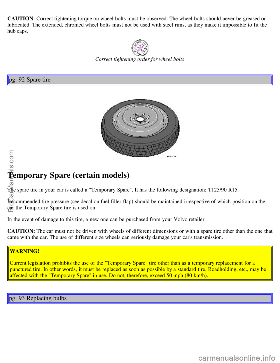
CAUTION: Correct tightening torque on wheel bolts must be observed. The wheel bolts should never be greased or
lubricated. The extended, chromed wheel bolts must not be used with steel rims, as they make it impossible to fit the
hub caps.
Correct tightening order for wheel bolts
pg. 92 Spare tire
Temporary Spare (certain models)
The spare tire in your car is called a "Temporary Spare". It has the following designation: T125/90 R15.
Recommended tire pressure (see decal on fuel filler flap) should be maintained irrespective of which position on the
car the Temporary Spare tire is used on.
In the event of damage to this tire, a new one can be purchased from your Volvo retailer.
CAUTION: The car must not be driven with wheels of different dimensions or with a spare tire other than the one that
came with the car. The use of different size wheels can seriously damage your car's transmission.
WARNING!
Current legislation prohibits the use of the "Temporary Spare" tire other than as a temporary replacement for a
punctured tire. In other words, it must be replaced as soon as possible by a standard tire. Roadholding, etc., may be
affected with the "Temporary Spare" in use. Do not, therefore, exceed 50 mph (80 km/h).
pg. 93 Replacing bulbs
ProCarManuals.com
Page 66 of 99
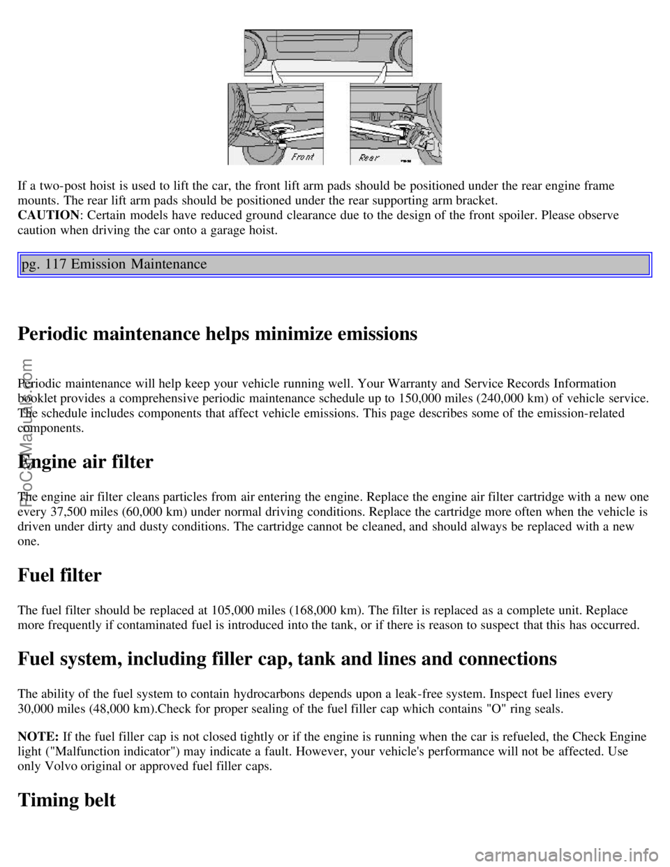
If a two-post hoist is used to lift the car, the front lift arm pads should be positioned under the rear engine frame
mounts. The rear lift arm pads should be positioned under the rear supporting arm bracket.
CAUTION: Certain models have reduced ground clearance due to the design of the front spoiler. Please observe
caution when driving the car onto a garage hoist.
pg. 117 Emission Maintenance
Periodic maintenance helps minimize emissions
Periodic maintenance will help keep your vehicle running well. Your Warranty and Service Records Information
booklet provides a comprehensive periodic maintenance schedule up to 150,000 miles (240,000 km) of vehicle service.
The schedule includes components that affect vehicle emissions. This page describes some of the emission-related
components.
Engine air filter
The engine air filter cleans particles from air entering the engine. Replace the engine air filter cartridge with a new one
every 37,500 miles (60,000 km) under normal driving conditions. Replace the cartridge more often when the vehicle is
driven under dirty and dusty conditions. The cartridge cannot be cleaned, and should always be replaced with a new
one.
Fuel filter
The fuel filter should be replaced at 105,000 miles (168,000 km). The filter is replaced as a complete unit. Replace
more frequently if contaminated fuel is introduced into the tank, or if there is reason to suspect that this has occurred.
Fuel system, including filler cap, tank and lines and connections
The ability of the fuel system to contain hydrocarbons depends upon a leak-free system. Inspect fuel lines every
30,000 miles (48,000 km).Check for proper sealing of the fuel filler cap which contains "O" ring seals.
NOTE: If the fuel filler cap is not closed tightly or if the engine is running when the car is refueled, the Check Engine
light ("Malfunction indicator") may indicate a fault. However, your vehicle's performance will not be affected. Use
only Volvo original or approved fuel filler caps.
Timing belt
ProCarManuals.com
Page 68 of 99
Evaporative control system
The car is equipped with an evaporative control system which prevents gasoline vapor from being released into the
atmosphere.
The system consists of a fuel tank with filler pipe and cap, a rollover valve, a Fill Limit Vent Valve (FLVV), vapor
vent lines, a charcoal canister, a purge line, a purge control valve and engine connections .
In addition, there is a pressure sensor connected to the fuel tank and a filter -protected Canister Close Valve (CCV) on
the atmospheric side of the canister, for system diagnosis.
The gasoline vapor is channeled through the rollover valve and the FLVV via the vapor vent lines into the charcoal
canister, where it is stored. When the engine is started, the gasoline vapor is drawn from the charcoal canister to the
engine's air intake system and into the combustion process.
NOTE:
If the fuel filler cap is not closed tightly or if the engine is running when the car is refueled, the Malfunction
Indicator Lamp may indicate a fault.
During a transitional period, a small number of service stations may still have fuel nozzles that are not compatible
with the fuel filler neck on cars equipped with the evaporative control system (ORVR) mandated by the U.S.
Environmental Protection Agency and the California Air Resources Board. If you experience difficulties in refueling
your vehicle, please ask the gas station attendant for assistance.
CAUTION:
Fuel must not be siphoned from the fuel tank. This will damage the Evaporative control system.
Contents | Top of Page
ProCarManuals.com
Page 69 of 99
2 0 0 2
VOLVO
C70 Coupe & Convertible
Chapter 9 - Specifications
pg. 129 Specifications
Page
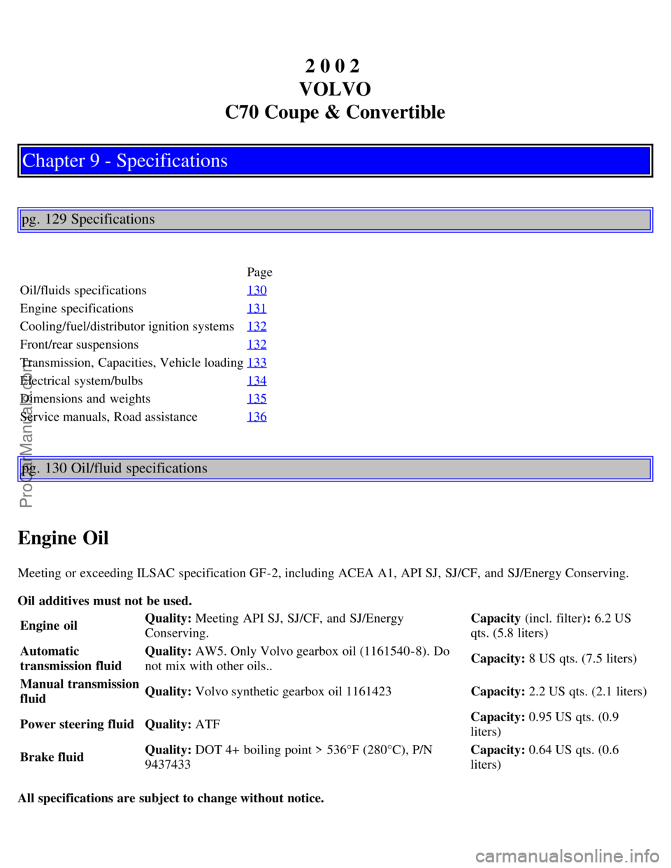
Oil/fluids specifications 130
Engine specifications131
Cooling/fuel/distributor ignition systems132
Front/rear suspensions132
Transmission, Capacities, Vehicle loading133
Electrical system/bulbs134
Dimensions and weights135
Service manuals, Road assistance136
pg. 130 Oil/fluid specifications
Engine Oil
Meeting or exceeding ILSAC specification GF-2, including ACEA A1, API SJ, SJ/CF, and SJ/Energy Conserving.
Oil additives must not be used.
Engine oil Quality:
Meeting API SJ, SJ/CF, and SJ/Energy
Conserving. Capacity (incl. filter)
: 6.2 US
qts. (5.8 liters)
Automatic
transmission fluid Quality:
AW5. Only Volvo gearbox oil (1161540-8). Do
not mix with other oils.. Capacity:
8 US qts. (7.5 liters)
Manual transmission
fluid Quality:
Volvo synthetic gearbox oil 1161423 Capacity: 2.2 US qts. (2.1 liters)
Power steering fluid Quality: ATF Capacity:
0.95 US qts. (0.9
liters)
Brake fluid Quality: DOT 4+ boiling point > 536°F (280°C), P/N
9437433 Capacity:
0.64 US qts. (0.6
liters)
All specifications are subject to change without notice.
ProCarManuals.com
Page 71 of 99

Cooling system
Type: Positive pressure, closed system
Thermostat begins to open at 180° F (87° C)
Coolant: Volvo original coolant/antifreeze
Capacity: 7.4 US qts. (7.0 liters)
Fuel system
The engine is equipped with a multiport fuel injection system.
Distributor ignition system
Firing order: 12453
Distributor ignition setting: Not adjustable
Spark plugs: Champion RC8PYP (or equivalent)
Spark plug gap: 0.03" (0.75 mm)
Tightening torque: 18.4 ft. lbs. +/ 3.7 ft. lbs. (25 Nm +/ 5 Nm)WARNING!
The distributor ignition system operates at very high voltages. Special safety precautions must be followed to
prevent injury. Always turn the ignition off when:
Replacing distributor ignition components e.g. plugs, coil, etc.
Do not touch any part of the distributor ignition system while the engine is running. This may result in unintended
movements and body injury.
All specifications are subject to change without notice.
Front suspension
Spring strut suspension with integrated shock absorbers and control arms linked to the support frame. Powerassisted
rack and pinion steering. Safety type steering column.
The alignment specifications apply to an unladen car but include fuel, coolant and spare wheel.
Toe-in measured on the wheel rims: 2.4 mm +/ 0.7 mm
Toe-in measured on tire sides: 2.9 +/ 0.9 mm
Rear suspension
Deltalink individual rear wheel suspension with longitudinal support arms, double link arms and track rods.
Toe-in measured on the tire sides: 4° +/ 10°
ProCarManuals.com
Page 72 of 99
pg. 133 Specifications
Power transmission
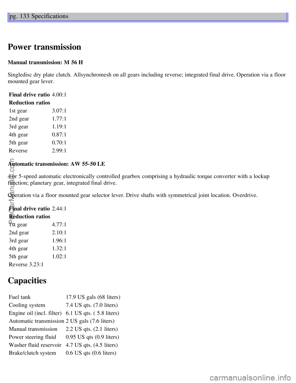
Manual transmission: M 56 H
Singledisc dry plate clutch. Allsynchromesh on all gears including reverse; integrated final drive. Operation via a floor
mounted gear lever.Final drive ratio 4.00:1
Reduction ratios
1st gear 3.07:1
2nd gear 1.77:1
3rd gear 1.19:1
4th gear 0.87:1
5th gear 0.70:1
Reverse 2.99:1
Automatic transmission: AW 55-50 LE
4 or 5-speed automatic electronically controlled gearbox comprising a hydraulic torque converter with a lockup
function; planetary gear, integrated final drive.
Operation via a floor mounted gear selector lever. Drive shafts with symmetrical joint location. Overdrive. Final drive ratio 2.44:1
Reduction ratios
1st gear 4.77:1
2nd gear 2.10:1
3rd gear 1.96:1
4th gear 1.32:1
5th gear 1.02:1
Reverse 3.23:1
Capacities
Fuel tank 17.9 US gals (68 liters)
Cooling system 7.4 US qts. (7.0 liters)
Engine oil (incl. filter) 6.1 US qts. ( 5.8 liters)
Automatic transmission 2 US gals (7.6 liters)
Manual transmission 2.2 US qts. (2.1 liters)
Power steering fluid 0.95 US qts (0.9 liters)
Washer fluid reservoir 4.7 US qts. (4.5 liters)
Brake/clutch system 0.6 US qts (0.6 liters)
ProCarManuals.com
Page 73 of 99
Vehicle loading
The tires on your Volvo should perform to specifications at all normal loads when inflated as recommended on the tire
information label. The label is located on the inside of the fuel filler flap. The label lists both tire and vehicle design
limits. Do not load your car beyond the load limits indicated.WARNING!
Improperly inflated tires will reduce tire life, adversely affect vehicle handling and can possibly lead to failure
resulting in loss of vehicle control without prior warning.
All specifications are subject to change without notice.
pg. 134 Specifications
Electrical system
12 Volt, negative ground.
Voltagecontrolled generator. Singlewire system with chassis and engine used as conductors.
Battery
Voltage 12 Volt
Capacity 520 A/100 min
(certain markets) 420 A/75 min
The battery contains corrosive and poisonous acids. It is of the utmost importance that old batteries are disposed of
correctly. Your Volvo retailer can assist you in this matter.
Generator
Rated output 1400 W
Max. current 100 A
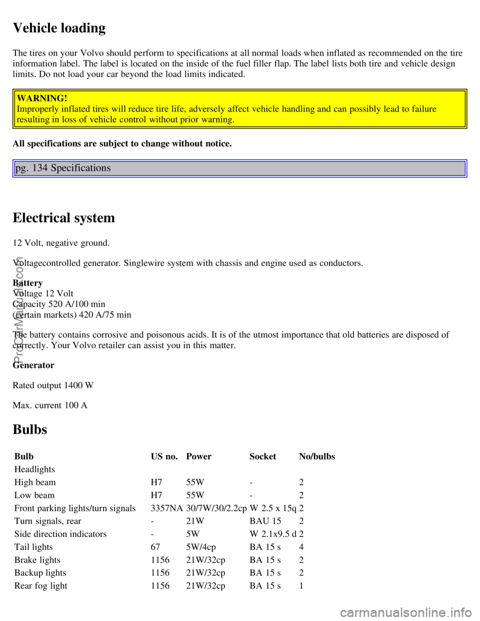
Bulbs
Bulb US no.Power SocketNo/bulbs
Headlights
High beam H755W -2
Low beam H755W -2
Front parking lights/turn signals 3357NA30/7W/30/2.2cp W 2.5 x 15q2
Turn signals, rear -21W BAU 152
Side direction indicators -5W W 2.1x9.5 d2
Tail lights 675W/4cp BA 15 s4
Brake lights 115621W/32cp BA 15 s2
Backup lights 115621W/32cp BA 15 s2
Rear fog light 115621W/32cp BA 15 s1
ProCarManuals.com
Page 98 of 99
A driver has a responsibility to do everything possible to ensure his or her own safety and the safety of passengers in
the vehicle and others sharing the roadway. Avoiding distractions is part of that responsibility.
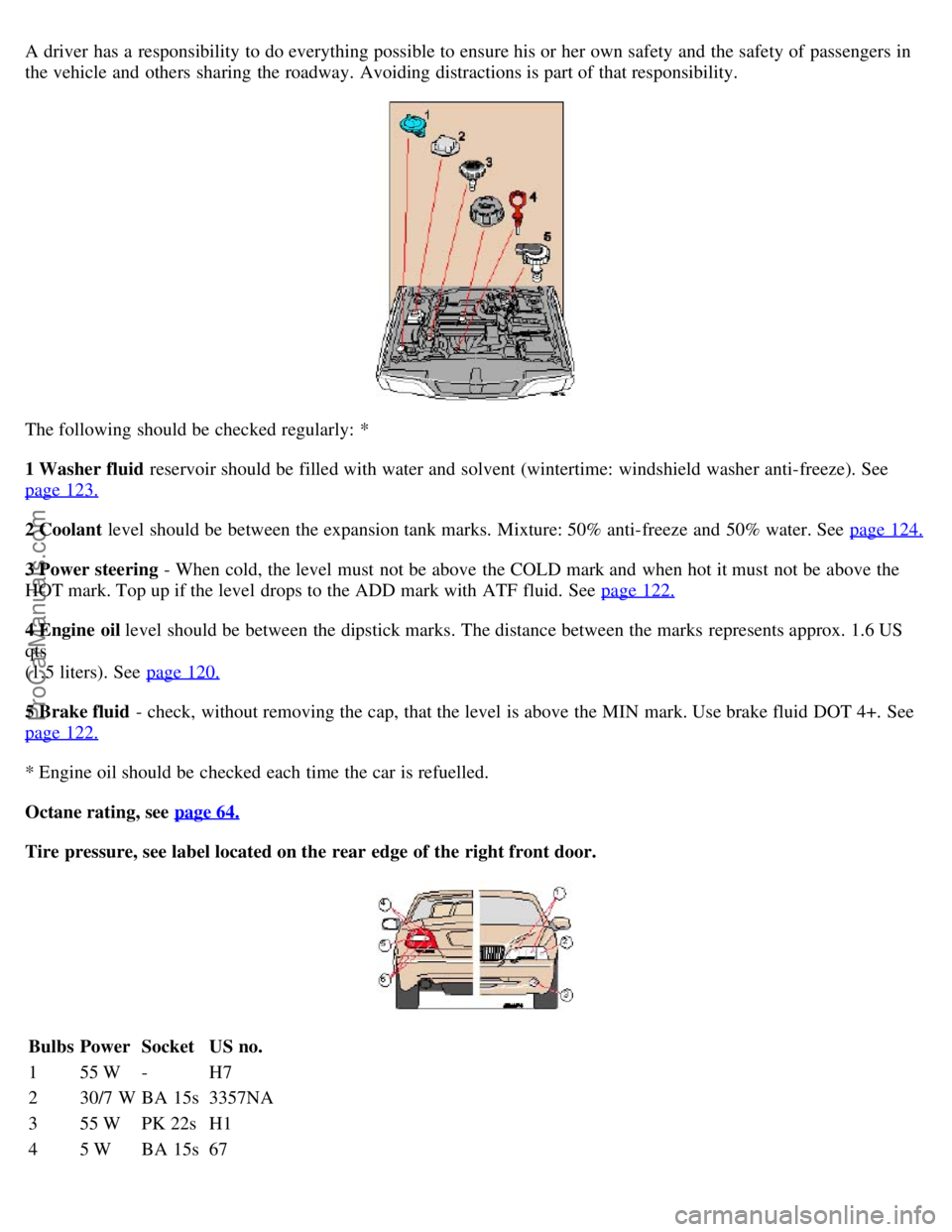
The following should be checked regularly: *
1 Washer fluid reservoir should be filled with water and solvent (wintertime: windshield washer anti-freeze). See
page 123.
2 Coolant level should be between the expansion tank marks. Mixture: 50% anti-freeze and 50% water. See page 124.
3 Power steering - When cold, the level must not be above the COLD mark and when hot it must not be above the
HOT mark. Top up if the level drops to the ADD mark with ATF fluid. See page 122.
4 Engine oil level should be between the dipstick marks. The distance between the marks represents approx. 1.6 US
qts
(1.5 liters). See page 120.
5 Brake fluid - check, without removing the cap, that the level is above the MIN mark. Use brake fluid DOT 4+. See
page 122.
* Engine oil should be checked each time the car is refuelled.
Octane rating, see page 64.
Tire pressure, see label located on the rear edge of the right front door.
Bulbs Power Socket US no.
1 55 W - H7
2 30/7 W BA 15s 3357NA
3 55 W PK 22s H1
4 5 W BA 15s 67
ProCarManuals.com