fuel filter VOLVO C70 2002 Owners Manual
[x] Cancel search | Manufacturer: VOLVO, Model Year: 2002, Model line: C70, Model: VOLVO C70 2002Pages: 99, PDF Size: 2.56 MB
Page 40 of 99
Whenever possible, avoid using the car for driving short distances. This does not allow the engine to reach normal
operating temperature.
Drive carefully and avoid rapid acceleration and hard braking.
Do not exceed speed limit.
Avoid carrying unnecessary items (extra load) in the car.
Maintain correct tire pressure. Check tire pressure regularly (check when tires are cold).
Remove snow tires when threat of snow or ice has ended.
Note that trunk-mounted luggage racks increase air resistance and thereby fuel consumption.
Avoid using automatic transmission kickdown feature unless necessary.
Avoid using the air conditioning when it is not required. When engaged, the air conditioner's compressor places an
additional load on the engine. However, please note that fuel consumption is lower with the air conditioning on than it
is when driving with the air conditioning switched off and the windows down.
If your car is equipped with the optional Trip Computer, utilizing the fuel consumption modes can help you "learn"
how to drive more economically.
Other factors which decrease gas mileage are:
Dirty air cleaner
Dirty engine oil and clogged oil filter
Dragging brakes
Incorrect front end alignment
Some of the above mentioned items and others are checked at the standard Maintenance Service intervals.
NOTE : (D)rive or 5th gear (manual transmissions) should be used as often as possible to help improve fuel economy.
pg. 68 Starting the Engine
Starting and stopping
1. Fasten the seat belt.
WARNING!
Before starting, check that the seat, steering wheel and mirrors are adjusted properly. Make sure the brake pedal can
be depressed completely. Move the seat closer if necessary. Refer to section "front seats".
2. Apply the parking brake, if not already set. The gear selector (automatic transmission) is locked in the (P)ark
position (SHIFT LOCK).
Manual transmission: the clutch must be fully depressed.
3. Without touching the accelerator pedal, turn the ignition key to the starting position*. Allow the starter to operate
for up to 10 seconds. Release the key as soon as the engine starts. If the engine fails to start, repeat step 3.
For cold starts at altitudes above 6000 ft (1800 meters), depress the accelerator pedal halfway and turn the key to the
starting position. Release the pedal slowly when the engine starts.
4. To release the gear selector from the (P)ark position (automatic transmission), the ignition key must be in position II
and the brake pedal must be depressed. See page 105 for instructions on manually releasing the SHIFTLOCK
ProCarManuals.com
Page 66 of 99
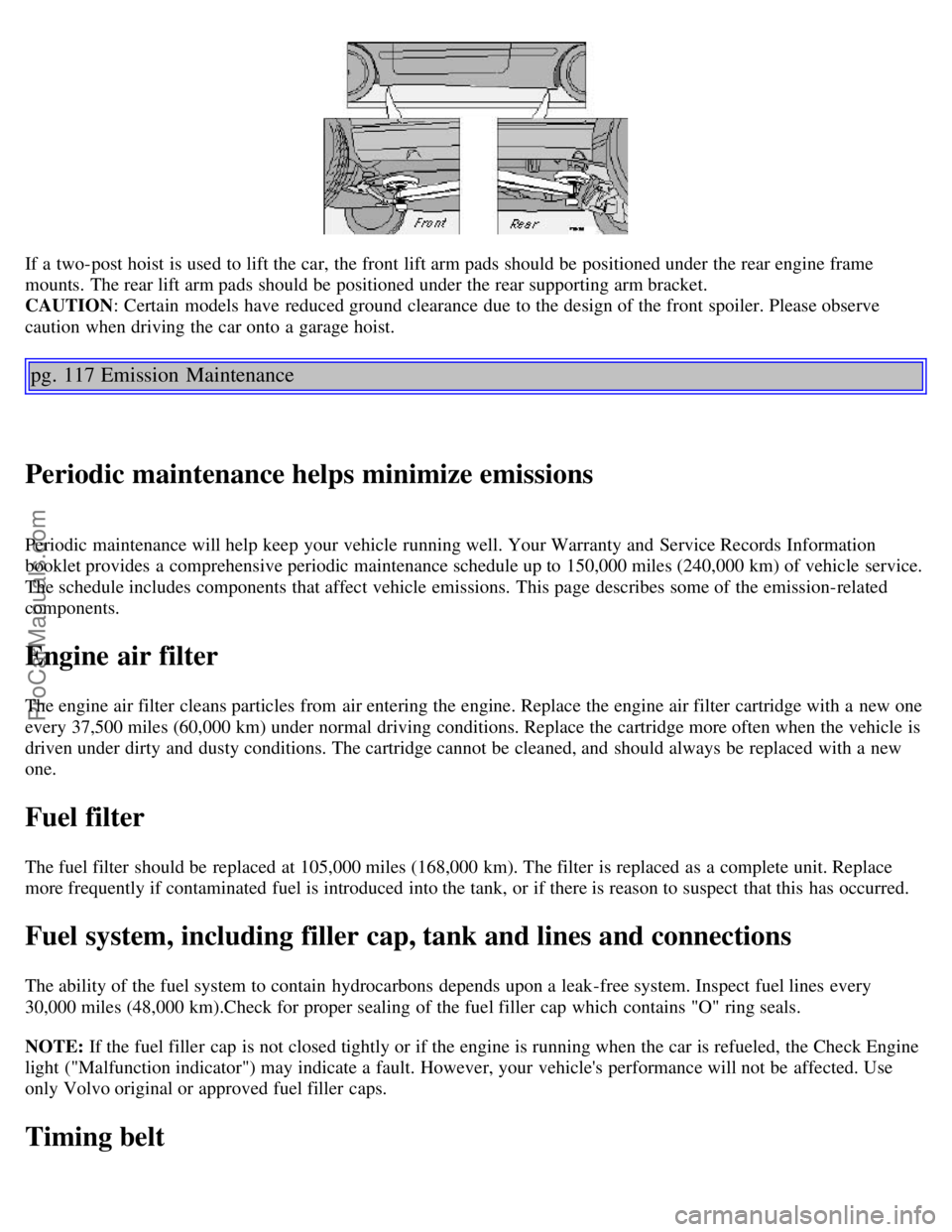
If a two-post hoist is used to lift the car, the front lift arm pads should be positioned under the rear engine frame
mounts. The rear lift arm pads should be positioned under the rear supporting arm bracket.
CAUTION: Certain models have reduced ground clearance due to the design of the front spoiler. Please observe
caution when driving the car onto a garage hoist.
pg. 117 Emission Maintenance
Periodic maintenance helps minimize emissions
Periodic maintenance will help keep your vehicle running well. Your Warranty and Service Records Information
booklet provides a comprehensive periodic maintenance schedule up to 150,000 miles (240,000 km) of vehicle service.
The schedule includes components that affect vehicle emissions. This page describes some of the emission-related
components.
Engine air filter
The engine air filter cleans particles from air entering the engine. Replace the engine air filter cartridge with a new one
every 37,500 miles (60,000 km) under normal driving conditions. Replace the cartridge more often when the vehicle is
driven under dirty and dusty conditions. The cartridge cannot be cleaned, and should always be replaced with a new
one.
Fuel filter
The fuel filter should be replaced at 105,000 miles (168,000 km). The filter is replaced as a complete unit. Replace
more frequently if contaminated fuel is introduced into the tank, or if there is reason to suspect that this has occurred.
Fuel system, including filler cap, tank and lines and connections
The ability of the fuel system to contain hydrocarbons depends upon a leak-free system. Inspect fuel lines every
30,000 miles (48,000 km).Check for proper sealing of the fuel filler cap which contains "O" ring seals.
NOTE: If the fuel filler cap is not closed tightly or if the engine is running when the car is refueled, the Check Engine
light ("Malfunction indicator") may indicate a fault. However, your vehicle's performance will not be affected. Use
only Volvo original or approved fuel filler caps.
Timing belt
ProCarManuals.com
Page 67 of 99

For proper functioning of the vehicle and its emission control systems, the timing belt and belt tensioner must be
replaced every 105,000 miles (168,000 km). Engine damage will occur if the belt fails.
PCV system
(on turbocharged models)
The nipple in the intake manifold and the filter at the end of the PCV hose in the air cleaner should be inspected and
cleaned at 105,000 miles (168,000 km) and thereafter, again at 150,000 mile (240,000 km) intervals.
Spark plugs
The spark plugs should be replaced every 60,000 miles (96,000 km) under normal driving conditions. City driving or
fast highway driving may necessitate replacement sooner.
Under normal driving conditions, spark plugs require no maintenance between replacement intervals. When installing
new plugs, be sure to use the right type and to tighten them correctly. When changing the plugs, clean the terminals
and rubber seals. Also check that the suppressor connectors are in good condition. Cracked or damaged connectors
should be replaced.
pg. 118 Fuel/emissions systems
Fuel system
The fuel system is allelectronic and is microprocessorcontrolled. It can continually compensate for variation in engine
load, speed and temperature to give the best economy and power. A mass air flow sensor measures the inducted air. In
this way the system can make instantaneous adjustments for changes in air temperature or density, thus always
assuring the best economy with the lowest possible exhaust emissions.
Heated oxygen sensor(s)
This is an emission control system designed to reduce emissions and improve fuel economy. The heated oxygen sensor
monitors the composition of the exhaust gases leaving the engine. The exhaust gas analysis is fed into an electronic
module. This adjusts the airfuel ratio to provide optimum conditions for combustion and efficient reduction of the three
major pollutants (hydrocarbons, carbon monoxide and oxides of nitrogen (NOx) by a threeway catalytic converter.
Crankcase ventilation
Crankcase ventilation
The engine is provided with positive crankcase ventilation which prevents crankcase gases from being released into the
atmosphere. Instead, the crankcase gases are admitted to the intake manifold and cylinders.
ProCarManuals.com
Page 68 of 99
Evaporative control system
The car is equipped with an evaporative control system which prevents gasoline vapor from being released into the
atmosphere.
The system consists of a fuel tank with filler pipe and cap, a rollover valve, a Fill Limit Vent Valve (FLVV), vapor
vent lines, a charcoal canister, a purge line, a purge control valve and engine connections .
In addition, there is a pressure sensor connected to the fuel tank and a filter -protected Canister Close Valve (CCV) on
the atmospheric side of the canister, for system diagnosis.
The gasoline vapor is channeled through the rollover valve and the FLVV via the vapor vent lines into the charcoal
canister, where it is stored. When the engine is started, the gasoline vapor is drawn from the charcoal canister to the
engine's air intake system and into the combustion process.
NOTE:
If the fuel filler cap is not closed tightly or if the engine is running when the car is refueled, the Malfunction
Indicator Lamp may indicate a fault.
During a transitional period, a small number of service stations may still have fuel nozzles that are not compatible
with the fuel filler neck on cars equipped with the evaporative control system (ORVR) mandated by the U.S.
Environmental Protection Agency and the California Air Resources Board. If you experience difficulties in refueling
your vehicle, please ask the gas station attendant for assistance.
CAUTION:
Fuel must not be siphoned from the fuel tank. This will damage the Evaporative control system.
Contents | Top of Page
ProCarManuals.com
Page 69 of 99
2 0 0 2
VOLVO
C70 Coupe & Convertible
Chapter 9 - Specifications
pg. 129 Specifications
Page
Oil/fluids specifications 130
Engine specifications131
Cooling/fuel/distributor ignition systems132
Front/rear suspensions132
Transmission, Capacities, Vehicle loading133
Electrical system/bulbs134
Dimensions and weights135
Service manuals, Road assistance136
pg. 130 Oil/fluid specifications
Engine Oil
Meeting or exceeding ILSAC specification GF-2, including ACEA A1, API SJ, SJ/CF, and SJ/Energy Conserving.
Oil additives must not be used.
Engine oil Quality:
Meeting API SJ, SJ/CF, and SJ/Energy
Conserving. Capacity (incl. filter)
: 6.2 US
qts. (5.8 liters)
Automatic
transmission fluid Quality:
AW5. Only Volvo gearbox oil (1161540-8). Do
not mix with other oils.. Capacity:
8 US qts. (7.5 liters)
Manual transmission
fluid Quality:
Volvo synthetic gearbox oil 1161423 Capacity: 2.2 US qts. (2.1 liters)
Power steering fluid Quality: ATF Capacity:
0.95 US qts. (0.9
liters)
Brake fluid Quality: DOT 4+ boiling point > 536°F (280°C), P/N
9437433 Capacity:
0.64 US qts. (0.6
liters)
All specifications are subject to change without notice.
ProCarManuals.com
Page 70 of 99

pg. 131 Engine specifications
Engine
Liquid-cooled gasoline, 5-cylinder, in-line engine. Aluminum alloy cylinder block with castiron cylinder liners cast
directly into the block. Aluminum alloy cylinder head with double overhead camshafts and separate intake and outlet
channels.
Engine lubrication is provided by an eccentric pump driven from the crankshaft. Fullflow type oil filter. Exhaust
emission control is accomplished by multiport fuel injection, heated oxygen sensor(s) and threeway catalytic converter.
Charge air cooler (Intercooler)
Turbocharged engines employ a turbocompressor to force air into the engine inlet manifold and a charge air cooler to
cool the compressed inlet air. The resulting increase in air flow raises pressure in the intake manifold by approx. 8.7
psi (over atmospheric pressure) and engine power output by approx. 50 horsepower over that developed by the
normallyaspirated engine. The charge air cooler (which resembles a radiator) is located between the turbocompressor
and inlet manifold.Designation: Volvo B 5234 T3
Output 236 hp at 5400 rpm (176 kw/90 rps)
Max. torque 243 ft. lbs. at 2400-5100 rpm (330 Nm/40-92 rps)
Number of cylinders 5
Bore 3.19" (81 mm)
Stroke 3.54" (90 mm)
Displacement 2.3 liters
Compression ratio 8.5:1
Number of valves 20
Designation: Volvo B 5244 T
Output 190 hp at 5100 rpm (142 kw/85 rps)
Max torque 199 ft. lbs. at 1800-5000 rpm (270 Nm/27-83 rps)
Number of cylinders 5
Bore 3.27" (83 mm)
Stroke 3.54" (90 mm)
Displacement 2.4 liters
Compression ratio 9.0:1
Number of valves 20
All specifications are subject to change without notice.
pg. 132 Specifications
ProCarManuals.com
Page 72 of 99
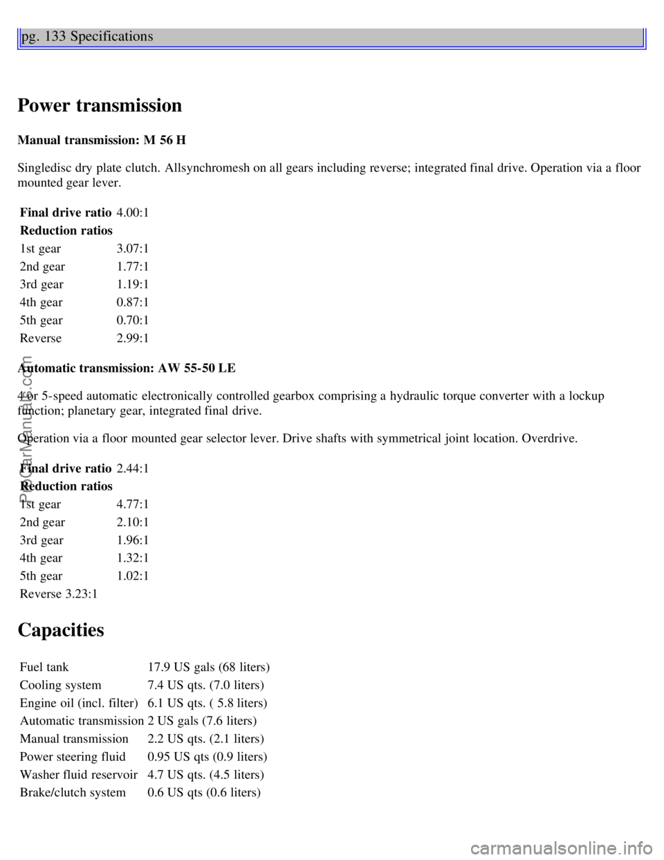
pg. 133 Specifications
Power transmission
Manual transmission: M 56 H
Singledisc dry plate clutch. Allsynchromesh on all gears including reverse; integrated final drive. Operation via a floor
mounted gear lever.Final drive ratio 4.00:1
Reduction ratios
1st gear 3.07:1
2nd gear 1.77:1
3rd gear 1.19:1
4th gear 0.87:1
5th gear 0.70:1
Reverse 2.99:1
Automatic transmission: AW 55-50 LE
4 or 5-speed automatic electronically controlled gearbox comprising a hydraulic torque converter with a lockup
function; planetary gear, integrated final drive.
Operation via a floor mounted gear selector lever. Drive shafts with symmetrical joint location. Overdrive. Final drive ratio 2.44:1
Reduction ratios
1st gear 4.77:1
2nd gear 2.10:1
3rd gear 1.96:1
4th gear 1.32:1
5th gear 1.02:1
Reverse 3.23:1
Capacities
Fuel tank 17.9 US gals (68 liters)
Cooling system 7.4 US qts. (7.0 liters)
Engine oil (incl. filter) 6.1 US qts. ( 5.8 liters)
Automatic transmission 2 US gals (7.6 liters)
Manual transmission 2.2 US qts. (2.1 liters)
Power steering fluid 0.95 US qts (0.9 liters)
Washer fluid reservoir 4.7 US qts. (4.5 liters)
Brake/clutch system 0.6 US qts (0.6 liters)
ProCarManuals.com
Page 92 of 99
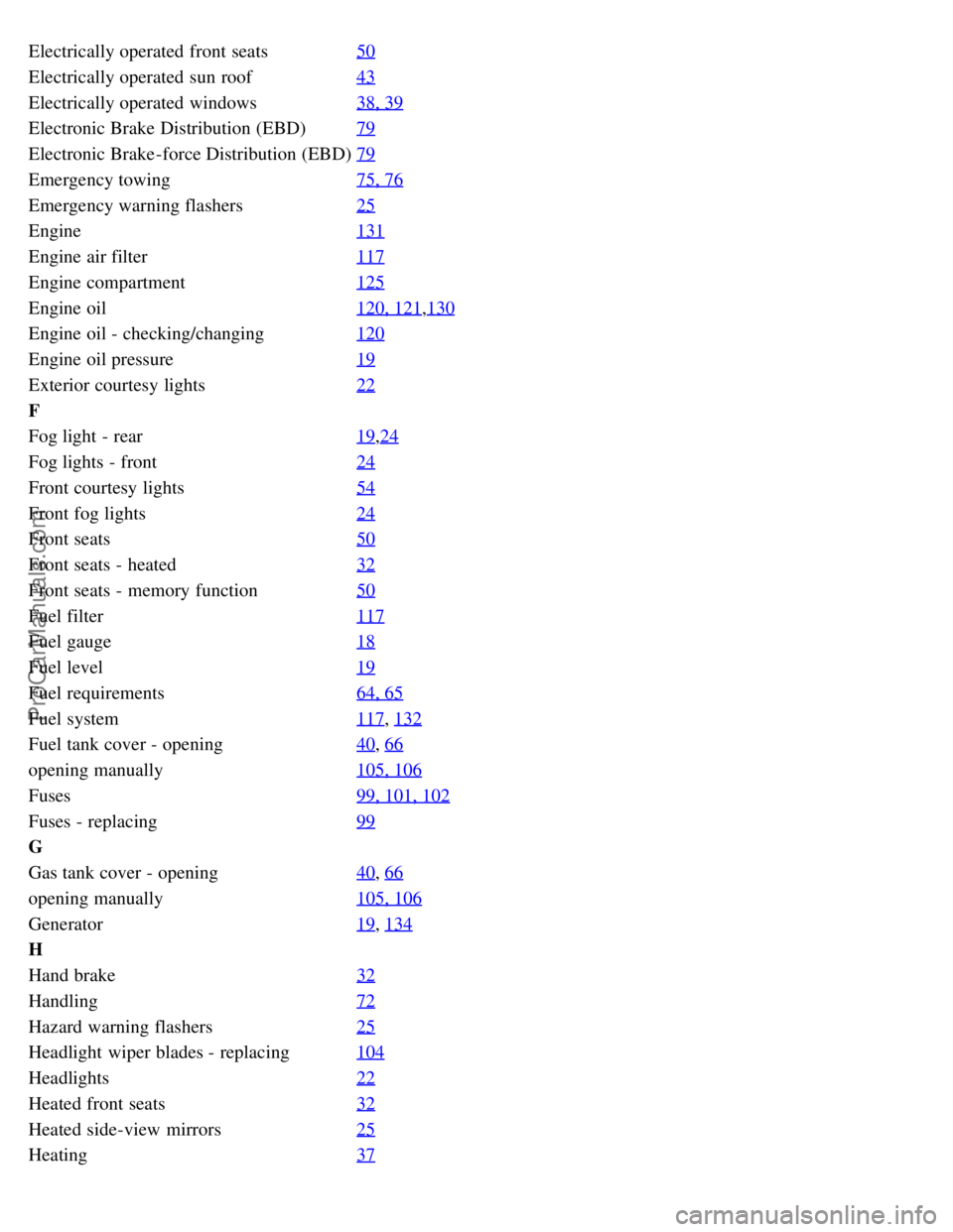
Electrically operated front seats50
Electrically operated sun roof43
Electrically operated windows38, 39
Electronic Brake Distribution (EBD)79
Electronic Brake-force Distribution (EBD)79
Emergency towing75, 76
Emergency warning flashers25
Engine131
Engine air filter117
Engine compartment125
Engine oil120, 121,130
Engine oil - checking/changing120
Engine oil pressure19
Exterior courtesy lights22
F
Fog light - rear19
,24
Fog lights - front24
Front courtesy lights54
Front fog lights24
Front seats50
Front seats - heated32
Front seats - memory function50
Fuel filter117
Fuel gauge18
Fuel level19
Fuel requirements64, 65
Fuel system117, 132
Fuel tank cover - opening40, 66
opening manually105, 106
Fuses99, 101, 102
Fuses - replacing99
G
Gas tank cover - opening40
, 66
opening manually105, 106
Generator19, 134
H
Hand brake32
Handling72
Hazard warning flashers25
Headlight wiper blades - replacing104
Headlights22
Heated front seats32
Heated side-view mirrors25
Heating37
ProCarManuals.com