instrument panel VOLVO C70 2012 Owner´s Manual
[x] Cancel search | Manufacturer: VOLVO, Model Year: 2012, Model line: C70, Model: VOLVO C70 2012Pages: 294, PDF Size: 7.02 MB
Page 4 of 294
Contents
4* Option/accessory, for more information, see Introduction.
00
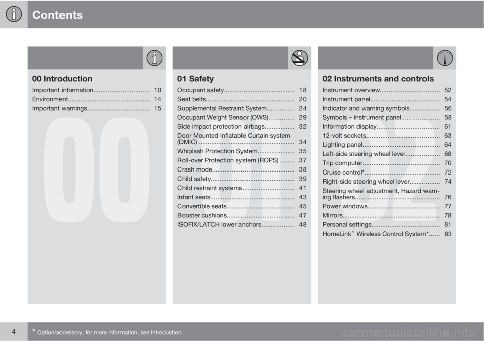
00 Introduction
Important information............................... 10
Environment.............................................. 14
Important warnings................................... 15
01
01 Safety
Occupant safety........................................ 18
Seat belts.................................................. 20
Supplemental Restraint System............... 24
Occupant Weight Sensor (OWS).............. 29
Side impact protection airbags................. 32
Door Mounted Inflatable Curtain system
(DMIC) ......................................................34
Whiplash Protection System..................... 35
Roll-over Protection system (ROPS) ........ 37
Crash mode.............................................. 38
Child safety............................................... 39
Child restraint systems............................. 41
Infant seats............................................... 43
Convertible seats...................................... 45
Booster cushions...................................... 47
ISOFIX/LATCH lower anchors.................. 48
02
02 Instruments and controls
Instrument overview.................................. 52
Instrument panel....................................... 54
Indicator and warning symbols.................56
Symbols – instrument panel..................... 58
Information display................................... 61
12-volt sockets......................................... 63
Lighting panel........................................... 64
Left-side steering wheel lever................... 68
Trip computer........................................... 70
Cruise control*.......................................... 72
Right-side steering wheel lever................. 74
Steering wheel adjustment, Hazard warn-
ing flashers................................................ 76
Power windows......................................... 77
Mirrors....................................................... 78
Personal settings...................................... 81
HomeLink
® Wireless Control System*...... 83
Page 22 of 294
01 Safety
Seat belts 01
22
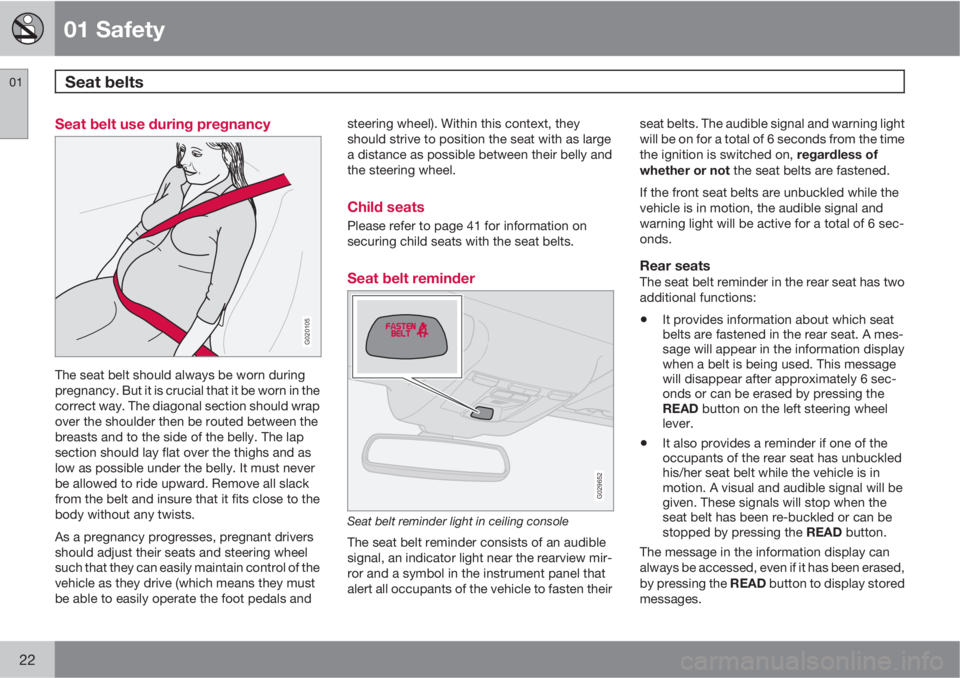
Seat belt use during pregnancy
G020105
The seat belt should always be worn during
pregnancy. But it is crucial that it be worn in the
correct way. The diagonal section should wrap
over the shoulder then be routed between the
breasts and to the side of the belly. The lap
section should lay flat over the thighs and as
low as possible under the belly. It must never
be allowed to ride upward. Remove all slack
from the belt and insure that it fits close to the
body without any twists.
As a pregnancy progresses, pregnant drivers
should adjust their seats and steering wheel
such that they can easily maintain control of the
vehicle as they drive (which means they must
be able to easily operate the foot pedals andsteering wheel). Within this context, they
should strive to position the seat with as large
a distance as possible between their belly and
the steering wheel.
Child seats
Please refer to page 41 for information on
securing child seats with the seat belts.
Seat belt reminder
G029652
Seat belt reminder light in ceiling console
The seat belt reminder consists of an audible
signal, an indicator light near the rearview mir-
ror and a symbol in the instrument panel that
alert all occupants of the vehicle to fasten theirseat belts. The audible signal and warning light
will be on for a total of 6 seconds from the time
the ignition is switched on, regardless of
whether or not the seat belts are fastened.
If the front seat belts are unbuckled while the
vehicle is in motion, the audible signal and
warning light will be active for a total of 6 sec-
onds.
Rear seatsThe seat belt reminder in the rear seat has two
additional functions:
•It provides information about which seat
belts are fastened in the rear seat. A mes-
sage will appear in the information display
when a belt is being used. This message
will disappear after approximately 6 sec-
onds or can be erased by pressing the
READ button on the left steering wheel
lever.
•It also provides a reminder if one of the
occupants of the rear seat has unbuckled
his/her seat belt while the vehicle is in
motion. A visual and audible signal will be
given. These signals will stop when the
seat belt has been re-buckled or can be
stopped by pressing the READ button.
The message in the information display can
always be accessed, even if it has been erased,
by pressing the READ button to display stored
messages.
Page 24 of 294
01 Safety
Supplemental Restraint System 01
24
Supplemental Restraint System (SRS)
G026330
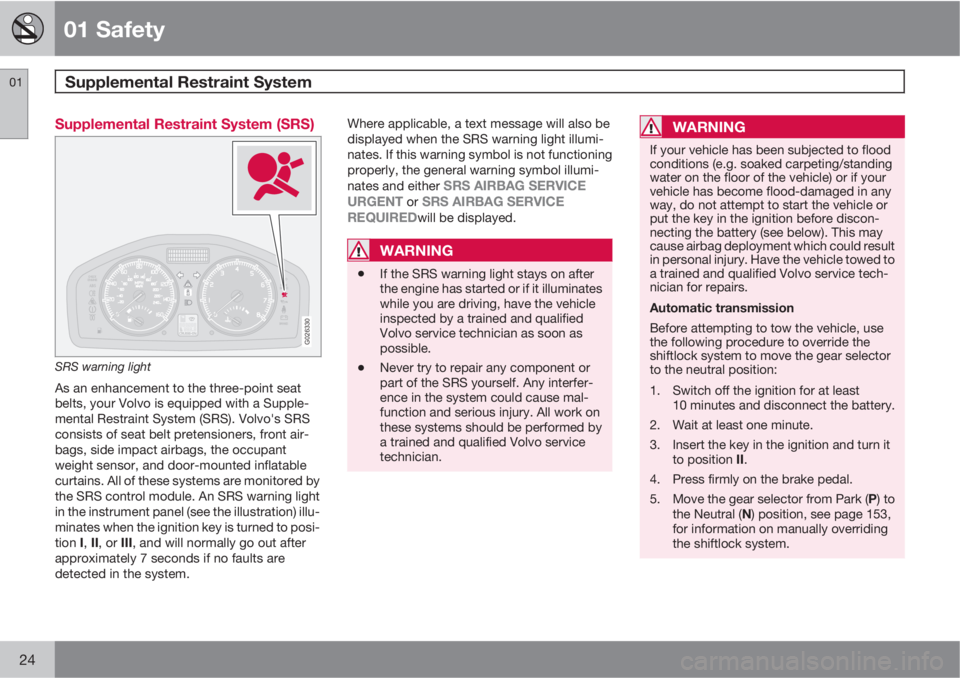
SRS warning light
As an enhancement to the three-point seat
belts, your Volvo is equipped with a Supple-
mental Restraint System (SRS). Volvo's SRS
consists of seat belt pretensioners, front air-
bags, side impact airbags, the occupant
weight sensor, and door-mounted inflatable
curtains. All of these systems are monitored by
the SRS control module. An SRS warning light
in the instrument panel (see the illustration) illu-
minates when the ignition key is turned to posi-
tion I, II, or III, and will normally go out after
approximately 7 seconds if no faults are
detected in the system.Where applicable, a text message will also be
displayed when the SRS warning light illumi-
nates. If this warning symbol is not functioning
properly, the general warning symbol illumi-
nates and either
SRS AIRBAG SERVICE
URGENT or SRS AIRBAG SERVICE
REQUIREDwill be displayed.
WARNING
•If the SRS warning light stays on after
the engine has started or if it illuminates
while you are driving, have the vehicle
inspected by a trained and qualified
Volvo service technician as soon as
possible.
•Never try to repair any component or
part of the SRS yourself. Any interfer-
ence in the system could cause mal-
function and serious injury. All work on
these systems should be performed by
a trained and qualified Volvo service
technician.
WARNING
If your vehicle has been subjected to flood
conditions (e.g. soaked carpeting/standing
water on the floor of the vehicle) or if your
vehicle has become flood-damaged in any
way, do not attempt to start the vehicle or
put the key in the ignition before discon-
necting the battery (see below). This may
cause airbag deployment which could result
in personal injury. Have the vehicle towed to
a trained and qualified Volvo service tech-
nician for repairs.
Automatic transmission
Before attempting to tow the vehicle, use
the following procedure to override the
shiftlock system to move the gear selector
to the neutral position:
1. Switch off the ignition for at least
10 minutes and disconnect the battery.
2. Wait at least one minute.
3. Insert the key in the ignition and turn it
to position II.
4. Press firmly on the brake pedal.
5.
Move the gear selector from Park (P) to
the Neutral (N) position, see page 153,
for information on manually overriding
the shiftlock system.
Page 28 of 294
01 Safety
Supplemental Restraint System 01
28
WARNING
•Children must never be allowed in the
front passenger's seat.
•Occupants in the front passenger's seat
must never sit on the edge of the seat,
sit leaning toward the instrument panel
or otherwise sit out of position.
•The occupant's back must be as upright
as comfort allows and be against the
seat back with the seat belt properly
fastened.
•Feet must be on the floor, e.g., not on
the dash, seat or out of the window.
WARNING
•No objects or accessory equipment,
e.g. dashboard covers, may be placed
on, attached to, or installed near the air
bag hatch (the area above the glove
compartment) or the area affected by
airbag deployment.
•There should be no loose articles, e.g.
coffee cups, on the floor, seat, or dash-
board area.
•Never try to open the airbag cover on
the steering wheel or the passenger's
side dashboard. This should only be
done by a trained and qualified Volvo
service technician.
•Failure to follow these instructions can
result in injury to the vehicle occupants.
Page 50 of 294
50* Option/accessory, for more information, see Introduction.
Instrument overview................................................................................ 52
Instrument panel..................................................................................... 54
Indicator and warning symbols............................................................... 56
Symbols – instrument panel.................................................................... 58
Information display.................................................................................. 61
12-volt sockets....................................................................................... 63
Lighting panel.......................................................................................... 64
Left-side steering wheel lever................................................................. 68
Trip computer.......................................................................................... 70
Cruise control*........................................................................................ 72
Right-side steering wheel lever............................................................... 74
Steering wheel adjustment, Hazard warning flashers............................. 76
Power windows....................................................................................... 77
Mirrors..................................................................................................... 78
Personal settings.................................................................................... 81
HomeLink
® Wireless Control System*.................................................... 83
Page 53 of 294
02 Instruments and controls
Instrument overview
02
* Option/accessory, for more information, see Introduction.53
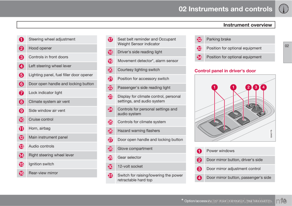
Steering wheel adjustment
Hood opener
Controls in front doors
Left steering wheel lever
Lighting panel, fuel filler door opener
Door open handle and locking button
Lock indicator light
Climate system air vent
Side window air vent
Cruise control
Horn, airbag
Main instrument panel
Audio controls
Right steering wheel lever
Ignition switch
Rear-view mirror
Seat belt reminder and Occupant
Weight Sensor indicator
Driver's side reading light
Movement detector*, alarm sensor
Courtesy lighting switch
Position for accessory switch
Passenger's side reading light
Display for climate control, personal
settings, and audio system
Controls for personal settings and
audio system
Controls for climate system
Hazard warning flashers
Door open handle and locking button
Glove compartment
Gear selector
12-volt socket
Switch for raising/lowering the power
retractable hard top
Parking brake
Position for optional equipment
Position for optional equipment
Control panel in driver's door
Power windows
Door mirror button, driver's side
Door mirror adjustment control
Door mirror button, passenger's side
Page 54 of 294

02 Instruments and controls
Instrument panel
02
54
Instrument panel
Speedometer
Turn signal, left
Warning symbol – See the following pages
for additional information.
Information display – The display presents
information and warning messages, the
ambient temperature, clock, etc. When the
ambient temperature is between 23 °F and
36 °F (–5 °C and +2 °C), a snowflake sym-
bol is shown in the display. This symbol
serves as a warning for possible slippery
road surfaces. Please note that this symbol
does not indicate a fault with your car. At
low speeds, or when the car is not moving,the temperature readings may be slightly
higher than the actual ambient tempera-
ture.
Information symbol – See the following
pages for additional information.
Turn signal, right
Tachometer – Shows engine speed in
thousands of revolutions per minute (rpm).
Do not drive continuously with the needle
in the red area of the dial, which indicates
maximum allowable engine rpm range.
Instead, shift to a higher gear or slow the
vehicle down. The engine management
system will automatically prevent exces-sively high engines speeds. This will be
noticeable as a pronounced unevenness in
engine speed.
Indicator and information symbols
Fuel gauge, see page 275 for fuel tank vol-
ume. When a warning light in the gauge
comes on, the vehicle should be refueled
as soon as possible, see page 70 for
more information on fuel level and con-
sumption in the "Trip computer” section.
High beam indicator
Function display – This window displays
information on functions such as the
Page 55 of 294

02 Instruments and controls
Instrument panel
02
55
odometer, trip odometers, optional rain
sensor, and cruise control.
Trip odometer reset button – The trip
odometers are used to measure short dis-
tances. Press the button briefly to switch
between the odometer for the car's total
mileage and the two trip odometers, T1
and T2. A long press (more than 2 seconds)
resets the currently selected trip odometer.
Temperature gauge – The gauge indicates
the temperature of the engine cooling sys-
tem. If the temperature is abnormally high
and the needle enters the red zone, a mes-
sage is shown in the display. Bear in mind
that auxiliary lamps in front of the air intake
reduce the cooling capacity at high outside
temperatures and high engine loads.
Indicator and warning symbols
Page 56 of 294
02 Instruments and controls
Indicator and warning symbols
02
56
Function check
The indicator and warning symbols1 light up
when you turn the ignition key or the optional
keyless drive start control to the driving posi-
tion (position II) before starting. This shows that
the symbols are functioning.
When the engine starts, all sym-
bols go out. If the engine is not
started within 5 seconds, all of the
symbols except the malfunction
indicator light (CHECK ENGINE)
and the oil pressure warning light
will go out. Certain symbols may
not have their functions illustrated, depending
on the car's equipment.
The PARK BRAKE symbol will not go out until
the parking brake has been released.
Symbols in the center of the instrument
panel
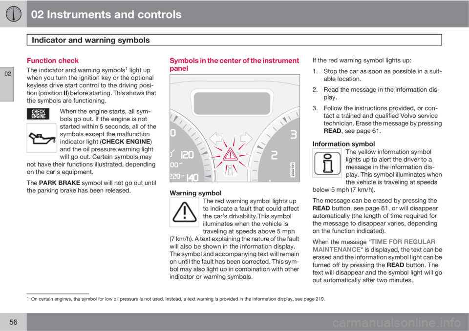
Warning symbolThe red warning symbol lights up
to indicate a fault that could affect
the car's drivability.This symbol
illuminates when the vehicle is
traveling at speeds above 5 mph
(7 km/h). A text explaining the nature of the fault
will also be shown in the information display.
The symbol and accompanying text will remain
on until the fault has been corrected. This sym-
bol may also light up in combination with other
indicator or warning symbols.
If the red warning symbol lights up:
1. Stop the car as soon as possible in a suit-
able location.
2. Read the message in the information dis-
play.
3. Follow the instructions provided, or con-
tact a trained and qualified Volvo service
technician. Erase the message by pressing
READ, see page 61.
Information symbolThe yellow information symbol
lights up to alert the driver to a
message in the information dis-
play. This symbol illuminates when
the vehicle is traveling at speeds
below 5 mph (7 km/h).
The message can be erased by pressing the
READ button, see page 61, or will disappear
automatically (the length of time required for
the message to disappear varies, depending
on the function indicated).
When the message "
TIME FOR REGULAR
MAINTENANCE" is displayed, the text can be
erased and the information symbol light can be
turned off by pressing the READ button. The
text will disappear and the symbol light will go
out automatically after two minutes.
1On certain engines, the symbol for low oil pressure is not used. Instead, a text warning is provided in the information display, see page 219.
Page 58 of 294

02 Instruments and controls
Symbols – instrument panel
02
58
Symbols – left side
G026439
1. Malfunction indicator light
As you drive, a computer called
On-Board Diagnostics II (OBDII)
monitors your car's engine, trans-
mission, electrical and emission
systems.
The CHECK ENGINE light will light up if the
computer senses a condition that potentially
may need correcting. When this happens,
please have your car checked by a trained and
qualified Volvo service technician as soon as
possible.
A CHECK ENGINE light may have many cau-
ses. Sometimes, you may not notice a change
in your car's behavior. Even so, an uncorrected
condition could hurt fuel economy, emission
controls, and drivability. Extended driving with-
out correcting the cause could even damage
other components in your car.
NOTE
Canadian models are equipped with the
second symbol.
2. Anti-lock Brake system (ABS)If the warning light comes on, there
is a malfunction of the ABS system
(the standard braking system will
still function).
The vehicle should be driven to a
trained and qualified Volvo service
technician for inspection, see
page 154 for additional informa-
tion.
NOTE
Canadian models are equipped with the
second symbol.
3. Rear fog lightThis symbol indicates that the rear
fog light (located in the driver's
side taillight cluster) is on.
4. Stability system DSTCThis indicator symbol flashes when
the DSTC (Dynamic Stability and
Traction control system) is actively
working to stabilize the car, see
page 158 for more detailed infor-
mation.
5. Tire Pressure Monitoring SystemThis system monitors inflation
pressure in the tires. See page
201 for more information.
6. Fuel level warning lightWhen this light comes on, the vehi-
cle should be refueled as soon as
possible.