window VOLVO S40 2008 Owners Manual
[x] Cancel search | Manufacturer: VOLVO, Model Year: 2008, Model line: S40, Model: VOLVO S40 2008Pages: 239, PDF Size: 5.94 MB
Page 2 of 239
In Canada: Volvo Cars of Canada Corp.
National Customer Service
175 Gordon Baker Road
North York, Ontario M2H 2N7
1-800-663-8255
www.volvocanada.com
2007 © Volvo Car Corporation. All rights reserved.
2 Contents
00 Introduction
General information 6
Volvo and the environment7
Important warnings8
01 Safety
Occupant safety 12
Seat belts14
Supplemental Restraint System17
Front airbags18
Occupant Weight Sensor (OWS)21
Side impact protection airbags24
Volvo Inflatable Curtain (VIC)25
Whiplash Protection System27
Crash mode29
Child safety30
Child restraint systems33
Infant seats35
Convertible seats37
Booster cushions40
ISOFIX lower anchors41
Top tether anchors42
Child restraint registration and
recalls43
02 Instruments and controls
Instrument overview
46
Instrument panel49
Indicator and warning symbols51
Symbols - instrument panel53
Information display56
12-volt sockets58
Lighting panel59
Left-side steering wheel lever62
Trip computer63
Cruise control65
Right-side steering wheel lever67
Rain sensor68
Steering wheel adjustment, Hazard
warning flashers69
Parking brake
70
Power windows71
Mirrors73
Power moonroof (option)75
ProCarManuals.com
Page 17 of 239
Children must never be allowed in the front passenger's seat. Volvo recommends that ALL occupants (adults and
children) shorter than 4 feet 7 inches (140 cm) be seated in the back seat of any vehicle with a passenger -side front
airbag. See page 32
for guidelines.
Occupants in the front passenger's seat must never sit on the edge of the seat, sit leaning toward the instrument
panel or otherwise sit out of position.
-The occupant's back must be as upright as comfort allows and be against the seat back with the seat belt properly
fastened.
Feet must be on the floor, e.g., not on the dash, seat or out of the window.
WARNING
No objects or accessory equipment, e.g. dashboard covers, may be placed on, attached to, or installed near the air
bag hatch (the area above the glove compartment) or the area affected by airbag deployment (see the illustration on
page 18
).
There should be no loose articles, e.g. coffee cups, on the floor, seat, or dashboard area.
Never try to open the airbag cover on the steering wheel or the passenger's side dashboard. This should only be
done by a trained and qualified Volvo service technician.
Failure to follow these instructions can result in injury to the vehicle occupants.
21 01 Safety
Occupant Weight Sensor (OWS)
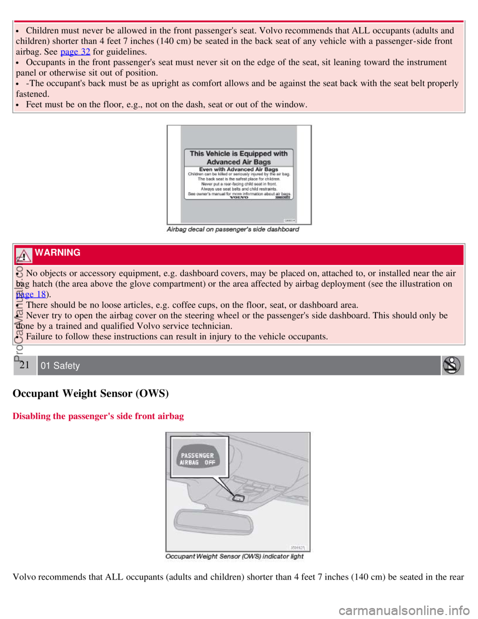
Disabling the passenger's side front airbag
Volvo recommends that ALL occupants (adults and children) shorter than 4 feet 7 inches (140 cm) be seated in the rear
ProCarManuals.com
Page 22 of 239
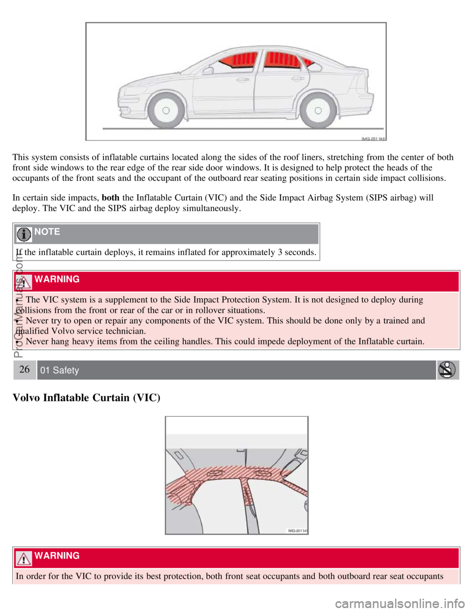
This system consists of inflatable curtains located along the sides of the roof liners, stretching from the center of both
front side windows to the rear edge of the rear side door windows. It is designed to help protect the heads of the
occupants of the front seats and the occupant of the outboard rear seating positions in certain side impact collisions.
In certain side impacts, both the Inflatable Curtain (VIC) and the Side Impact Airbag System (SIPS airbag) will
deploy. The VIC and the SIPS airbag deploy simultaneously.
NOTE
If the inflatable curtain deploys, it remains inflated for approximately 3 seconds.
WARNING
The VIC system is a supplement to the Side Impact Protection System. It is not designed to deploy during
collisions from the front or rear of the car or in rollover situations.
Never try to open or repair any components of the VIC system. This should be done only by a trained and
qualified Volvo service technician.
Never hang heavy items from the ceiling handles. This could impede deployment of the Inflatable curtain.
26 01 Safety
Volvo Inflatable Curtain (VIC)
WARNING
In order for the VIC to provide its best protection, both front seat occupants and both outboard rear seat occupants
ProCarManuals.com
Page 39 of 239
2 0 0 8
VOLVO S40
44 02 Instruments and controls
Instrument overview 46
Instrument panel49
Indicator and warning symbols51
Symbols - instrument panel53
Information display56
12-volt sockets58
Lighting panel59
Left-side steering wheel lever62
Trip computer63
Cruise control65
Right-side steering wheel lever67
Rain sensor68
Steering wheel adjustment, Hazard warning flashers69
Parking brake70
Power windows71
Mirrors73
Power moonroof (option)75
Personal settings77
HomeLink® Universal Transceiver (option)80
45 02 Instruments and controls
46 02 Instruments and controls
Instrument overview
ProCarManuals.com
Page 40 of 239
47 02 Instruments and controls
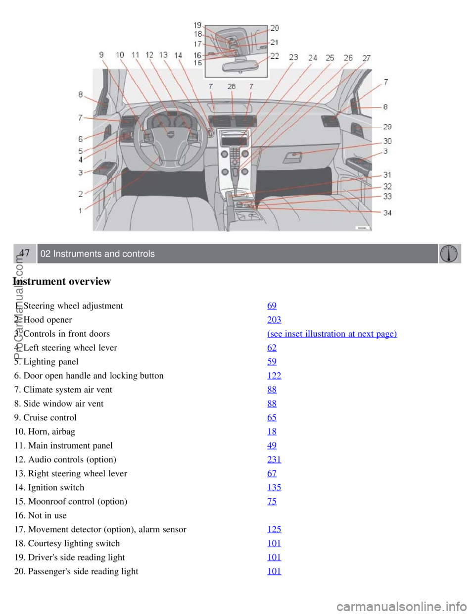
Instrument overview
1. Steering wheel adjustment69
2. Hood opener203
3. Controls in front doors(see inset illustration at next page)
4. Left steering wheel lever62
5. Lighting panel59
6. Door open handle and locking button122
7. Climate system air vent88
8. Side window air vent88
9. Cruise control65
10. Horn, airbag18
11. Main instrument panel49
12. Audio controls (option)231
13. Right steering wheel lever67
14. Ignition switch135
15. Moonroof control (option)75
16. Not in use
17. Movement detector (option), alarm sensor125
18. Courtesy lighting switch101
19. Driver's side reading light101
20. Passenger's side reading light101
ProCarManuals.com
Page 41 of 239
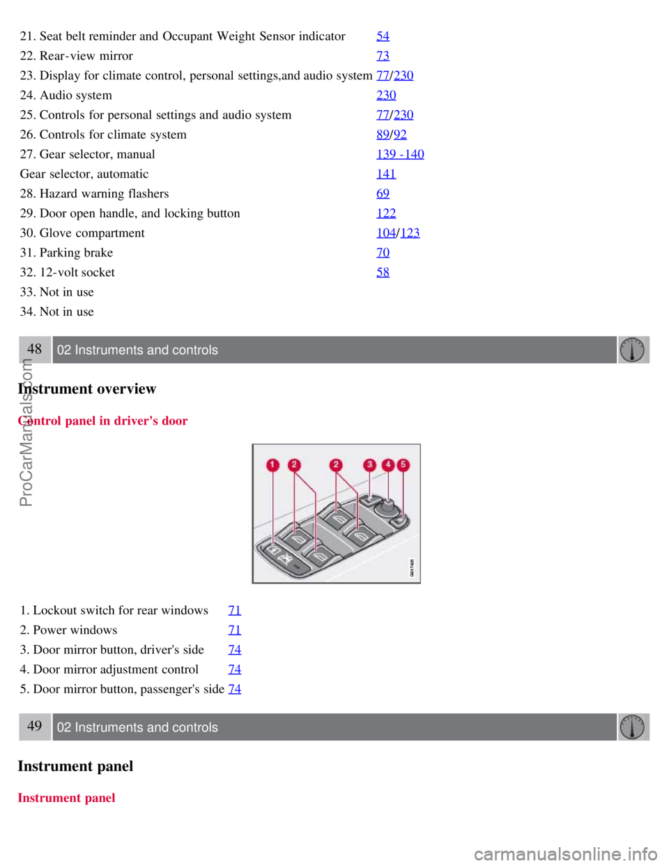
21. Seat belt reminder and Occupant Weight Sensor indicator54
22. Rear-view mirror73
23. Display for climate control, personal settings,and audio system77/230
24. Audio system 230
25. Controls for personal settings and audio system77/230
26. Controls for climate system 89/92
27. Gear selector, manual 139 -140
Gear selector, automatic141
28. Hazard warning flashers69
29. Door open handle, and locking button122
30. Glove compartment104/123
31. Parking brake 70
32. 12-volt socket58
33. Not in use
34. Not in use
48 02 Instruments and controls
Instrument overview
Control panel in driver's door
1. Lockout switch for rear windows71
2. Power windows71
3. Door mirror button, driver's side74
4. Door mirror adjustment control74
5. Door mirror button, passenger's side74
49 02 Instruments and controls
Instrument panel
Instrument panel
ProCarManuals.com
Page 42 of 239
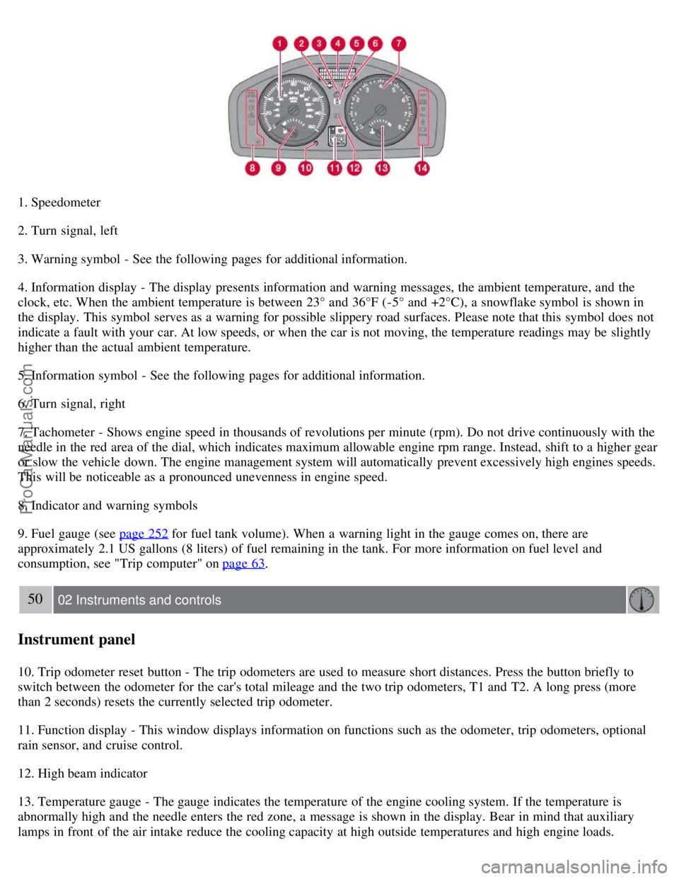
1. Speedometer
2. Turn signal, left
3. Warning symbol - See the following pages for additional information.
4. Information display - The display presents information and warning messages, the ambient temperature, and the
clock, etc. When the ambient temperature is between 23° and 36°F (-5° and +2°C), a snowflake symbol is shown in
the display. This symbol serves as a warning for possible slippery road surfaces. Please note that this symbol does not
indicate a fault with your car. At low speeds, or when the car is not moving, the temperature readings may be slightly
higher than the actual ambient temperature.
5. Information symbol - See the following pages for additional information.
6. Turn signal, right
7. Tachometer - Shows engine speed in thousands of revolutions per minute (rpm). Do not drive continuously with the
needle in the red area of the dial, which indicates maximum allowable engine rpm range. Instead, shift to a higher gear
or slow the vehicle down. The engine management system will automatically prevent excessively high engines speeds.
This will be noticeable as a pronounced unevenness in engine speed.
8. Indicator and warning symbols
9. Fuel gauge (see page 252
for fuel tank volume). When a warning light in the gauge comes on, there are
approximately 2.1 US gallons (8 liters) of fuel remaining in the tank. For more information on fuel level and
consumption, see "Trip computer" on page 63
.
50 02 Instruments and controls
Instrument panel
10. Trip odometer reset button - The trip odometers are used to measure short distances. Press the button briefly to
switch between the odometer for the car's total mileage and the two trip odometers, T1 and T2. A long press (more
than 2 seconds) resets the currently selected trip odometer.
11. Function display - This window displays information on functions such as the odometer, trip odometers, optional
rain sensor, and cruise control.
12. High beam indicator
13. Temperature gauge - The gauge indicates the temperature of the engine cooling system. If the temperature is
abnormally high and the needle enters the red zone, a message is shown in the display. Bear in mind that auxiliary
lamps in front of the air intake reduce the cooling capacity at high outside temperatures and high engine loads.
ProCarManuals.com
Page 62 of 239
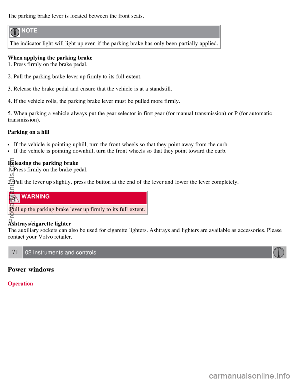
The parking brake lever is located between the front seats.
NOTE
The indicator light will light up even if the parking brake has only been partially applied.
When applying the parking brake
1. Press firmly on the brake pedal.
2. Pull the parking brake lever up firmly to its full extent.
3. Release the brake pedal and ensure that the vehicle is at a standstill.
4. If the vehicle rolls, the parking brake lever must be pulled more firmly.
5. When parking a vehicle always put the gear selector in first gear (for manual transmission) or P (for automatic
transmission).
Parking on a hill
If the vehicle is pointing uphill, turn the front wheels so that they point away from the curb.
If the vehicle is pointing downhill, turn the front wheels so that they point toward the curb.
Releasing the parking brake
1. Press firmly on the brake pedal.
2. Pull the lever up slightly, press the button at the end of the lever and lower the lever completely.
WARNING
Pull up the parking brake lever up firmly to its full extent.
Ashtrays/cigarette lighter
The auxiliary sockets can also be used for cigarette lighters. Ashtrays and lighters are available as accessories. Please
contact your Volvo retailer.
71 02 Instruments and controls
Power windows
Operation
ProCarManuals.com
Page 63 of 239
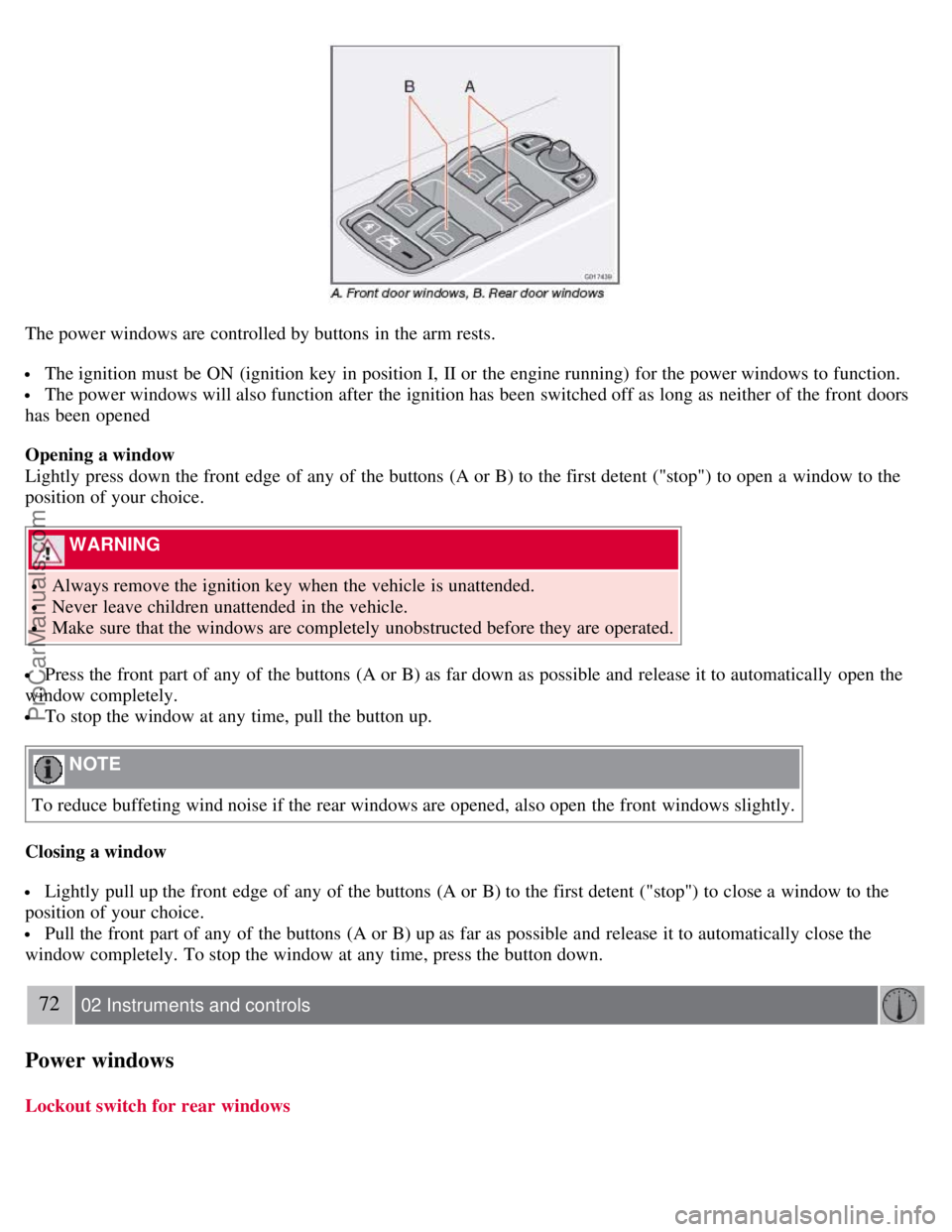
The power windows are controlled by buttons in the arm rests.
The ignition must be ON (ignition key in position I, II or the engine running) for the power windows to function.
The power windows will also function after the ignition has been switched off as long as neither of the front doors
has been opened
Opening a window
Lightly press down the front edge of any of the buttons (A or B) to the first detent ("stop") to open a window to the
position of your choice.
WARNING
Always remove the ignition key when the vehicle is unattended.
Never leave children unattended in the vehicle.
Make sure that the windows are completely unobstructed before they are operated.
Press the front part of any of the buttons (A or B) as far down as possible and release it to automatically open the
window completely.
To stop the window at any time, pull the button up.
NOTE
To reduce buffeting wind noise if the rear windows are opened, also open the front windows slightly.
Closing a window
Lightly pull up the front edge of any of the buttons (A or B) to the first detent ("stop") to close a window to the
position of your choice.
Pull the front part of any of the buttons (A or B) up as far as possible and release it to automatically close the
window completely. To stop the window at any time, press the button down.
72 02 Instruments and controls
Power windows
Lockout switch for rear windows
ProCarManuals.com
Page 64 of 239
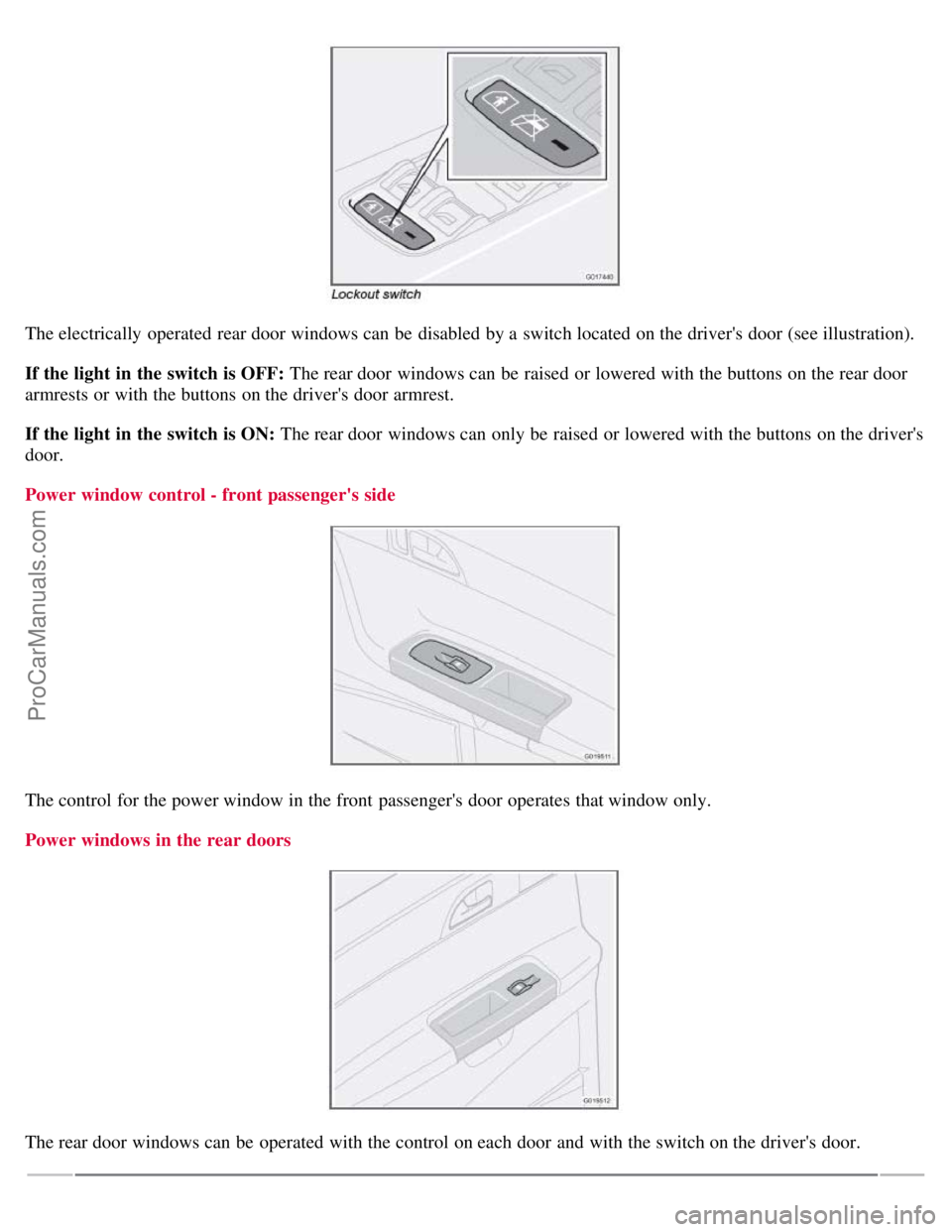
The electrically operated rear door windows can be disabled by a switch located on the driver's door (see illustration).
If the light in the switch is OFF: The rear door windows can be raised or lowered with the buttons on the rear door
armrests or with the buttons on the driver's door armrest.
If the light in the switch is ON: The rear door windows can only be raised or lowered with the buttons on the driver's
door.
Power window control - front passenger's side
The control for the power window in the front passenger's door operates that window only.
Power windows in the rear doors
The rear door windows can be operated with the control on each door and with the switch on the driver's door.
ProCarManuals.com