engine VOLVO S60 2015 Owner´s Manual
[x] Cancel search | Manufacturer: VOLVO, Model Year: 2015, Model line: S60, Model: VOLVO S60 2015Pages: 406, PDF Size: 11.26 MB
Page 187 of 406
04 Driver support
Driver Alert System*
04
}}
* Option/accessory, for more information, see Introduction.185
Introduction
The Driver Alert System is designed to help a driver who may be becoming fatigued or whois inadvertently leaving the lane and consistsof two different functions that can beswitched on together or separately.
• Driver Alert Control (DAC)
• Lane Departure Warning (LDW) 1
, see
page 187
• Lane Keeping Aid (LKA) 2
, see page 190
When one or both of the functions has beenswitched on, it is in standby mode and is acti-vated when the vehicle exceeds a speed of40 mph (65 km/h). The function deactivates if the vehicle's speed goes under 37 mph (60 km/h). Both functions use a camera that is depend- ent on the road/lane being clearly marked bypainted lines on each side.
WARNING
The Driver Alert System does not function in all situations and is designed to be asupplementary aid. It is not, however,intended to replace the driver’s attentionand judgement.
Driver Alert Control (DAC)
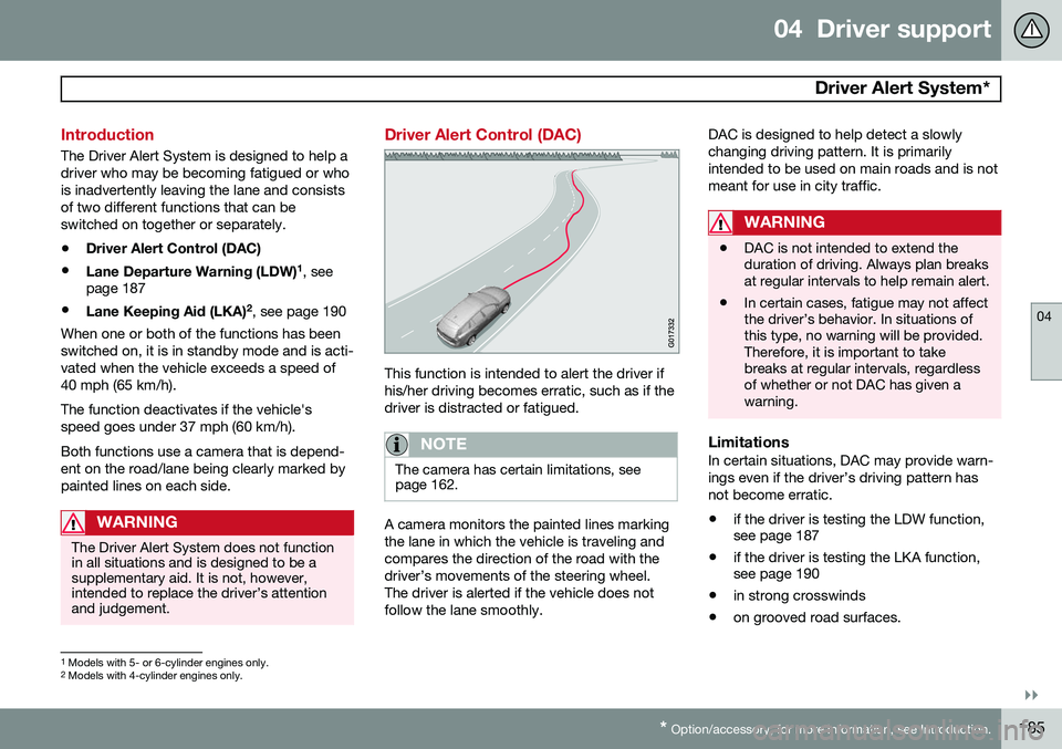
This function is intended to alert the driver if his/her driving becomes erratic, such as if thedriver is distracted or fatigued.
NOTE
The camera has certain limitations, see page 162.
A camera monitors the painted lines marking the lane in which the vehicle is traveling andcompares the direction of the road with thedriver’s movements of the steering wheel.The driver is alerted if the vehicle does notfollow the lane smoothly. DAC is designed to help detect a slowlychanging driving pattern. It is primarilyintended to be used on main roads and is notmeant for use in city traffic.
WARNING
•
DAC is not intended to extend the duration of driving. Always plan breaksat regular intervals to help remain alert.
• In certain cases, fatigue may not affectthe driver’s behavior. In situations ofthis type, no warning will be provided.Therefore, it is important to takebreaks at regular intervals, regardlessof whether or not DAC has given awarning.
LimitationsIn certain situations, DAC may provide warn- ings even if the driver’s driving pattern hasnot become erratic.
• if the driver is testing the LDW function, see page 187
• if the driver is testing the LKA function,see page 190
• in strong crosswinds
• on grooved road surfaces.
1
Models with 5- or 6-cylinder engines only.
2 Models with 4-cylinder engines only.
Page 189 of 406
04 Driver support
Driver Alert System*
04
}}
* Option/accessory, for more information, see Introduction.187
Center console display
SymbolMessageDescription
-Driver Alert OFFThe function is not switched on.
-Driver Alert AvailableThe function is active.
-Driver Alert Standby <65 km/hThe function has gone into standby mode because the vehicle's speed is below 40 mph (65 km/h).
-Driver Alert UnavailableThe camera is temporarily not functioning, due to snow, ice, or dirt on the windshield. Clean the area of the windshield in front of the camera. See page 179 for information on the camera’s limita-tions.
Lane Departure Warning (LDW) 1
Your vehicle may be equipped with Lane Departure Warning (LDW) or Lane KeepingAid (LKA), depending on your choice of engine.
If you are uncertain as to which of
these optional systems is in your vehicle:
• Press the
MY CAR button on the center
console to open the menu system. Scroll to
SettingsDriver support system.
The system in your vehicle (Lane
Departure Warning or Lane Keeping
Aid) will be displayed there.
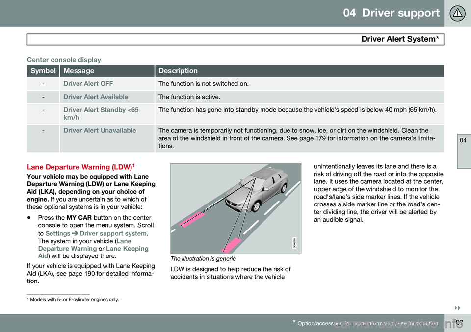
If your vehicle is equipped with Lane Keeping Aid (LKA), see page 190 for detailed informa-tion.The illustration is generic
LDW is designed to help reduce the risk of accidents in situations where the vehicle unintentionally leaves its lane and there is arisk of driving off the road or into the oppositelane. It uses the camera located at the center,upper edge of the windshield to monitor theroad's/lane’s side marker lines. If the vehiclecrosses a side marker line or the road’s cen-ter dividing line, the driver will be alerted byan audible signal.
1
Models with 5- or 6-cylinder engines only.
Page 191 of 406
04 Driver support
Driver Alert System*
04
}}
* Option/accessory, for more information, see Introduction.189
Car
. Go to
SettingsCar settings
Driver support systemsLane Departure
Warning.
There are two alternatives:
On at start-up: This selection switches LDW
on each time the engine is started. Otherwise, the system will be in the mode that it was in when the engine was switched off.
Increased sensitivity: This selection increa-
ses the function’s sensitivity. Warnings will be given at an earlier stage and fewer limitationsapply. When this setting is being used, thesystem only needs to monitor lane marker lines on one side of the vehicle to change sta- tus to
Lane Depart Warn Available.
Symbols and messages
SymbolMessageDescription
Lane departure warning ON/Lane departure warning OFFThe function is switched on or off. The text disappears after 5 seconds.
-Lane Depart Warn AvailableThe function is monitoring the road’s marker lines.
-Lane Depart. Warning Unavail-
able at this speedThe function has gone into standby mode because the vehicle's speed is below 40 mph (65 km/h).
-Lane Depart Warn UnavailableThe road lacks clear marker lines or the camera is not functioning properly. See page 179 for information on the camera’s limitations.
Windscreen Sensors blockedThe camera is temporarily not functioning, due to snow, ice, or dirt on the windshield. Clean the area of the windshield in front of the camera. See page 179 for information on the camera’s limi-tations.
Driver Alert Sys Service requiredThe system is not functioning. Contact a trained and qualified Volvo service technician if the message remains in the display.
Page 192 of 406
04 Driver support
Driver Alert System*
04
190* Option/accessory, for more information, see Introduction.
Lane Keeping Aid (LKA) 2
See page 187 for information about determin- ing if your vehicle is equipped with LaneDeparture Warning or Lane Keeping Aid This function is designed to help reduce the risk of accidents in situations where the vehi-cle unintentionally leaves its lane and there isa risk of driving off the road or into the oppo-site lane. It is primarily intended for use onhighways or other major roads with clearlymarked side marker and center lines.
How LKA works
The illustration is generic
LKA uses the camera located at the center, upper edge of the windshield to monitor theroad's/lane’s side marker lines. If the vehicle crosses a side marker line or theroad’s center dividing line, LKA will provideactive steering assistance to help steer itback into the lane. The driver will also be alerted by vibrations in the steering wheel.
WARNING
This feature is only intended to assist the driver and does not function in all driving,weather, traffic or road conditions. As the driver, you have full responsibility for operating the vehicle in a safe manner.
Operation and functionLKA is active at speeds above 40 mph (65 km/h) on highways or other major roadswith clearly marked side/lane marker andcenter lines. On narrow roads where the dis-tance between side/lane marker lines is lessthan approximately 8.5 feet ( 2.6 meters), LKAwill be temporarily deactivated.
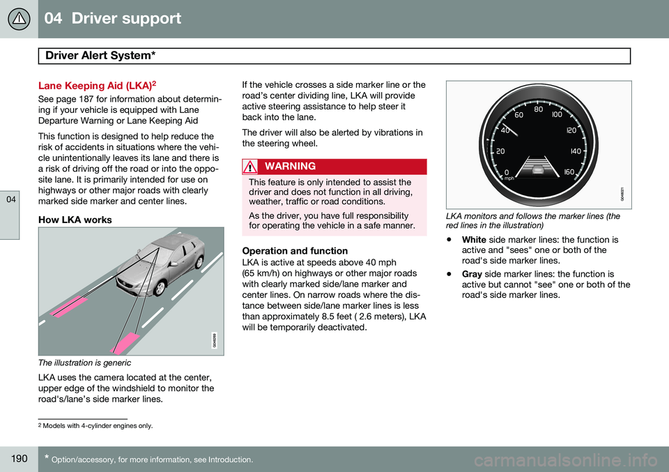
LKA monitors and follows the marker lines (the red lines in the illustration)
• White
side marker lines: the function is
active and "sees" one or both of the road's side marker lines.
• Gray
side marker lines: the function is
active but cannot "see" one or both of theroad's side marker lines.
2 Models with 4-cylinder engines only.
Page 196 of 406
04 Driver support
Park assist*
04
194* Option/accessory, for more information, see Introduction.
Introduction
The park assist system is designed to assist you when driving into parking spaces,garages, etc. It utilizes ultrasound sensors inthe front bumper and rear bumper(s) to meas-ure the distance to a vehicle or an object thatmay be close to the front or rear of your vehi-cle. An audible signal and symbols in theaudio system’s display indicate the distanceto the object.
NOTE
A trailer hitch whose wiring is integrated with the vehicle's electrical system will beincluded in the measurement of the availa-ble space behind the vehicle.
WARNING
Park Assist is an information system, NOT a safety system. This system is designedto be a supplementary aid when parkingthe vehicle. It is not, however, intended toreplace the driver's attention and judge-ment.
Function
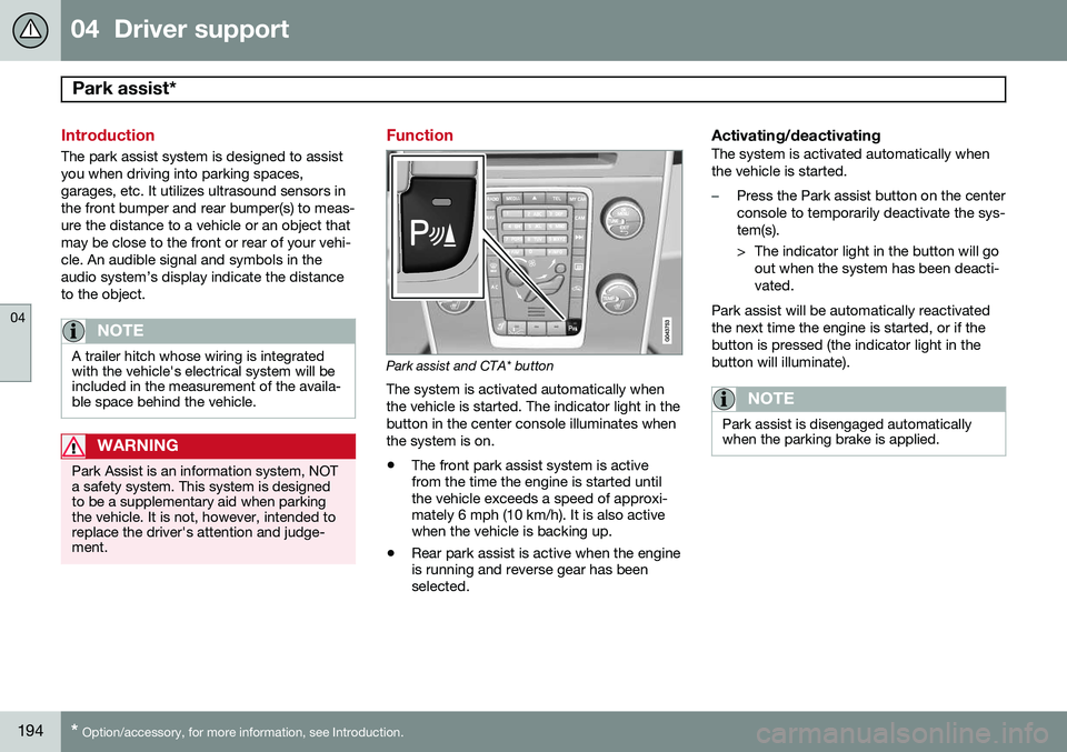
Park assist and CTA* button
The system is activated automatically when the vehicle is started. The indicator light in thebutton in the center console illuminates whenthe system is on.
• The front park assist system is active from the time the engine is started untilthe vehicle exceeds a speed of approxi-mately 6 mph (10 km/h). It is also activewhen the vehicle is backing up.
• Rear park assist is active when the engineis running and reverse gear has beenselected.
Activating/deactivatingThe system is activated automatically when the vehicle is started.
–Press the Park assist button on the center console to temporarily deactivate the sys-tem(s).
> The indicator light in the button will go
out when the system has been deacti- vated.
Park assist will be automatically reactivatedthe next time the engine is started, or if thebutton is pressed (the indicator light in thebutton will illuminate).
NOTE
Park assist is disengaged automatically when the parking brake is applied.
Page 208 of 406
04 Driver support
Blind Spot Information System (BLIS)*
04
206* Option/accessory, for more information, see Introduction.
Introduction
BLIS is an information system that indicates the presence of another vehicle moving in thesame direction as your vehicle on roads withseveral lanes. The system helps provide infor-mation about:
• Other vehicles in your door mirrors' "blind area"
• Vehicles that are about to pass your vehi-cle in the left and/or right lanes
• Cross Traffic Alert (CTA) is a supple- mentary BLIS function
intended to
detect vehicles crossing behind your vehicle while you are backing up.WARNING
• BLIS and CTA are information sys- tems, NOT warning or safety systemsand do not function in all situations.
• BLIS and CTA do not eliminate theneed for you to visually confirm theconditions around you, and the needfor you to turn your head and should-ers to make sure that you can safelychange lanes or back up.
• As the driver, you have full responsibil-ity for changing lanes/backing up in asafe manner.
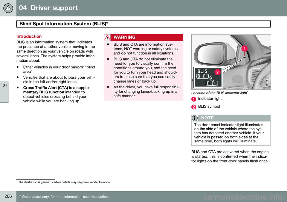
Location of the BLIS indicator light 1
.
Indicator light
BLIS symbol
NOTE
The door panel indicator light illuminates on the side of the vehicle where the sys-tem has detected another vehicle. If yourvehicle is passed on both sides at thesame time, both lights will illuminate.
BLIS and CTA are activated when the engine is started; this is confirmed when the indica-tor lights on the front door panels flash once.
1 The illustration is generic; certain details may vary from model to model
Page 216 of 406
05 Comfort and driving pleasure
Menus and messages
05
214
Messages
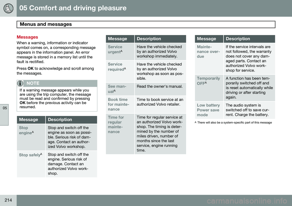
When a warning, information or indicator symbol comes on, a corresponding messageappears in the information panel. An errormessage is stored in a memory list until thefault is rectified. Press OK to acknowledge and scroll among
the messages.
NOTE
If a warning message appears while you are using the trip computer, the messagemust be read and confirmed by pressingOK before the previous activity can be
resumed.
MessageDescription
Stop engineAStop and switch off the engine as soon as possi-ble. Serious risk of dam-age. Contact an author-ized Volvo workshop.
Stop safelyAStop and switch off the engine. Serious risk ofdamage. Contact anauthorized Volvo work-shop.
MessageDescription
Service urgentAHave the vehicle checked by an authorized Volvoworkshop immediately.
Service requiredAHave the vehicle checked by an authorized Volvoworkshop as soon as pos-sible.
See man- ualARead the owner's manual.
Book time for mainte-nanceTime to book service at an authorized Volvo retailer.
Time for regularmainte-nanceTime for regular service at an authorized Volvo work-shop. The timing is deter-mined by the number ofmiles driven, number ofmonths since the lastservice, engine runningtime.
MessageDescription
Mainte- nance over-dueIf the service intervals are not followed, the warrantydoes not cover any dam-aged parts. Contact anauthorized Volvo work-shop for service.
Temporarily OFFAA function has been tem- porarily switched off andis reset automatically whiledriving or after startingagain.
Low battery Power savemodeThe audio system is switched off to save cur-rent. Charge the battery.
A There will also be a system-specific part of this message
Page 227 of 406
05 Comfort and driving pleasure
Climate system
05
}}
* Option/accessory, for more information, see Introduction.225
Climate system controls
Heated front seats*
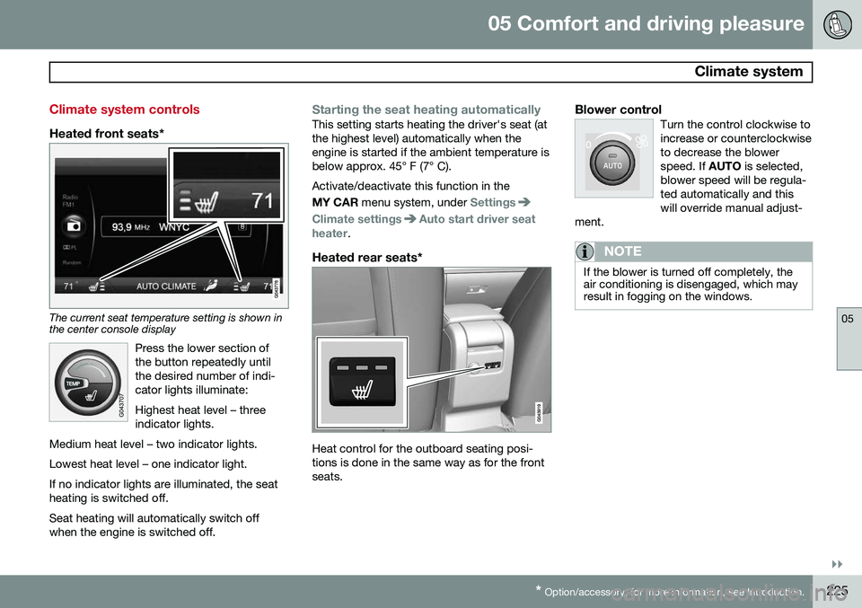
The current seat temperature setting is shown in the center console display
Press the lower section of the button repeatedly untilthe desired number of indi-cator lights illuminate: Highest heat level – three indicator lights.
Medium heat level – two indicator lights. Lowest heat level – one indicator light.If no indicator lights are illuminated, the seat heating is switched off.
Seat heating will automatically switch off when the engine is switched off.
Starting the seat heating automaticallyThis setting starts heating the driver's seat (at the highest level) automatically when theengine is started if the ambient temperature isbelow approx. 45° F (7° C). Activate/deactivate this function in the MY CAR menu system, under
Settings
Climate settingsAuto start driver seat
heater.
Heated rear seats*
Heat control for the outboard seating posi- tions is done in the same way as for the frontseats.
Blower controlTurn the control clockwise toincrease or counterclockwiseto decrease the blowerspeed. If AUTO is selected,
blower speed will be regula-ted automatically and thiswill override manual adjust-
ment.
NOTE
If the blower is turned off completely, the air conditioning is disengaged, which mayresult in fogging on the windows.
Page 232 of 406
05 Comfort and driving pleasure
Trip computer
05
230
Introduction
The content and appearance of the trip com- puter varies depending on whether the vehi-cle is equipped with an analog or digital
instrument panel. The instrument panel illuminates as soon as the vehicle is unlocked and trip computer set-tings can be made. If none of the trip com-puter's controls are used within 30 secondsafter the driver's door has been opened, theinstrument panel lighting will go out and thetrip computer cannot be used again until: • the ignition is put in mode II1
• the engine is started
NOTE
If a warning message appears while you are using the trip computer, this messagemust be acknowledged in order to returnto the trip computer function. Acknowl-edge a message by pressing
OK.
Trip computer in models with an analog instrument panel
The trip computer has two different menu groups: •
Trip computer functions
• Trip computer information headings in the instrument panel
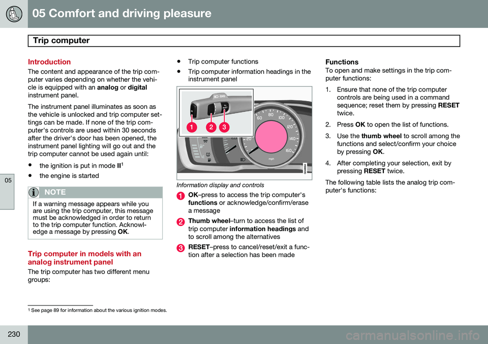
Information display and controls
OK
–press to access the trip computer's
functions or acknowledge/confirm/erase
a message
Thumb wheel –turn to access the list of
trip computer information headings and
to scroll among the alternatives
RESET –press to cancel/reset/exit a func-
tion after a selection has been made
FunctionsTo open and make settings in the trip com- puter functions:
1. Ensure that none of the trip computer controls are being used in a command sequence; reset them by pressing RESET
twice.
2. Press OK to open the list of functions.
3. Use the thumb wheel to scroll among the
functions and select/confirm your choiceby pressing OK.
4. After completing your selection, exit by pressing RESET twice.
The following table lists the analog trip com-puter's functions:
1 See page 89 for information about the various ignition modes.
Page 237 of 406
05 Comfort and driving pleasure
Trip computer
05
* Option/accessory, for more information, see Introduction.235
Resetting a digital instrument panel
Trip odometer1. Turn the thumb wheel to select the com-
bination of headings containing the trip odometer to be reset.
2. Press and hold RESET until selected trip
odometer is reset.
Average speed and fuel consumption1. Select Trip computer reset and press
OK .
2. Select one of the following alternatives using the thumb wheel and press OK:
• mpg
• mph
• Reset both
3. Finish by pressing RESET.
Changing unitsTo change the unit (miles/km) used to meas- ure distance and speed, go to
MY CAR
SettingsSystem optionsDistance
and fuel units.
NOTE
In addition to changing units in the trip computer, this also changes the units usedin the Volvo Navigation System (VNS)*.
Trip statistics*
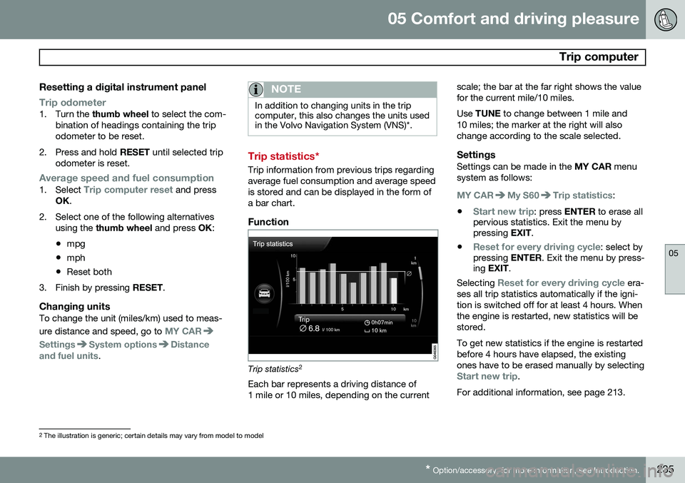
Trip information from previous trips regarding average fuel consumption and average speedis stored and can be displayed in the form ofa bar chart.
Function
Trip statistics 2
Each bar represents a driving distance of 1 mile or 10 miles, depending on the current scale; the bar at the far right shows the valuefor the current mile/10 miles. Use
TUNE to change between 1 mile and
10 miles; the marker at the right will also change according to the scale selected.
SettingsSettings can be made in the MY CAR menu
system as follows:
MY CARMy S60Trip statistics:
•
Start new trip: press ENTER to erase all
pervious statistics. Exit the menu by pressing EXIT.
•
Reset for every driving cycle: select by
pressing ENTER. Exit the menu by press-
ing EXIT .
Selecting
Reset for every driving cycle era-
ses all trip statistics automatically if the igni- tion is switched off for at least 4 hours. Whenthe engine is restarted, new statistics will bestored. To get new statistics if the engine is restarted before 4 hours have elapsed, the existingones have to be erased manually by selecting
Start new trip.
For additional information, see page 213.
2 The illustration is generic; certain details may vary from model to model