clock VOLVO S60 2016 Owner´s Manual
[x] Cancel search | Manufacturer: VOLVO, Model Year: 2016, Model line: S60, Model: VOLVO S60 2016Pages: 392, PDF Size: 10.04 MB
Page 278 of 392
||
08 Starting and driving
08
276
3. Gently pull the cord straight rearward untilthe fuel filler door clicks open.
Related information
• Refueling – opening/closing fuel cap (p. 276)
• Refueling – fuel requirements (p. 273)
• Refueling – octane rating (p. 274)
Refueling – opening/closing fuel cap
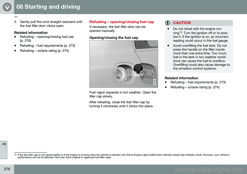
If necessary, the fuel filler door can be opened manually.
Opening/closing the fuel cap
Fuel vapor expands in hot weather. Open the filler cap slowly. After refueling, close the fuel filler cap by turning it clockwise until it clicks into place.
CAUTION
• Do not refuel with the engine run- ning 13
. Turn the ignition off or to posi-
tion I. If the ignition is on, an incorrect
reading could occur in the fuel gauge.
• Avoid overfilling the fuel tank. Do not press the handle on the filler nozzlemore than one extra time. Too muchfuel in the tank in hot weather condi-tions can cause the fuel to overflow.Overfilling could also cause damage tothe emission control systems.
Related information
•
Refueling – fuel requirements (p. 273)
• Refueling – octane rating (p. 274)
13
If the fuel filler cap is not closed tightly or if the engine is running when the vehicle is refueled, the Check Engine Light (malfunction indicator lamp) may indicate a fault. However, your vehicle's performance will not be affected. Use only Volvo original or approved fuel filler caps.
Page 291 of 392
09 Wheels and tires
09
}}
289
3.
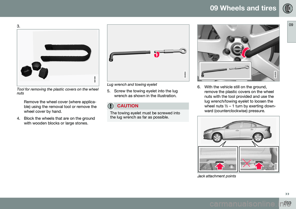
Tool for removing the plastic covers on the wheel nuts
Remove the wheel cover (where applica- ble) using the removal tool or remove thewheel cover by hand.
4. Block the wheels that are on the ground with wooden blocks or large stones.Lug wrench and towing eyelet
5. Screw the towing eyelet into the lug wrench as shown in the illustration.
CAUTION
The towing eyelet must be screwed into the lug wrench as far as possible.
6. With the vehicle still on the ground,remove the plastic covers on the wheel nuts with the tool provided and use thelug wrench/towing eyelet to loosen thewheel nuts ½ – 1 turn by exerting down-ward (counterclockwise) pressure.
Jack attachment points
Page 317 of 392

09 Wheels and tires
09
}}
* Option/accessory, for more information, see Introduction.315
Tire sealing system – checking inflation pressure
The tire sealing system can also be used to check the tires' inflation pressure.
Stage 2: Checking inflation pressure1. Connect the tire sealing system as
described in stage 1, see Tire sealing
system* – sealing hole (p. 313).
2. Refer to the inflation pressure table in this chapter for the correct inflation pressure.If the tire needs to be inflated, start thetire sealing system’s compressor. If nec-essary, release air from the tire by turningthe air release knob counterclockwise.
CAUTION
The compressor should not be used for more than 10 minutes at a time to avoidoverheating.
WARNING
If you interrupt your trip for more than 1 hour, check the inflation pressure in thedamaged tire again before continuing.
Tire sealing system* – inflating tires
The tire sealing system can be used to inflate the tires. To do so:
1. Park the car in a safe place.
2. The compressor should be switched off.Ensure that the on/off switch is in position0 (the 0 side of the switch should be
pressed down).
3. Take out the electrical wire and hose.
4. Remove the valve cap from the tire’s inflation valve and screw the hose con- nector onto the valve as tightly as possi-ble by hand.
5. Connect the electrical wire to the nearest 12-volt socket in the vehicle.
6. Start the vehicle’s engine.WARNING
• The vehicle’s engine should be running when the tire sealing system is used toavoid battery drain. Therefore, be surethe vehicle is parked in a well ventilatedplace, or outdoors, before using thesystem. The parking brake should besecurely applied and the gear selectorshould be in the
P (park) position.
• Children should never be left unatten-ded in the vehicle when the engine isrunning.
7. Check the tire’s inflation pressure on the
gauge. Switch off the compressor briefly to get a clear reading from the pressuregauge.
8. Refer to the tire inflation table in this chapter for the correct inflation pressure.If the tire needs to be inflated, start thetire sealing system’s compressor (pressthe on/off switch to position I). If neces-sary, release air from the tire by turningthe air release knob counterclockwise.
Page 325 of 392
10 Maintenance and servicing
10
323
where any retailer can access or search for this information using your vehicle's VIN num-ber. This number can be found in your war-ranty booklet or on the dashboard at thelower left corner of the windshield.
–Select Maintenance & repairSend
vehicle data.
Booking information and vehicle dataWhen you opt to book service from your vehi- cle, booking information and vehicle data willbe transmitted. Vehicle data consists of anumber of parameters in the following areas:
• Service requirements
• Function status
• Fluid levels
• Odometer reading (mileage)
• Vehicle Identification Number (VIN)
• The vehicle's software version
Related information
•Volvo ID (p. 21)
Maintenance – opening/closing hood
The hood is opened by first releasing the lock from the passenger compartment and thenpressing the release control.
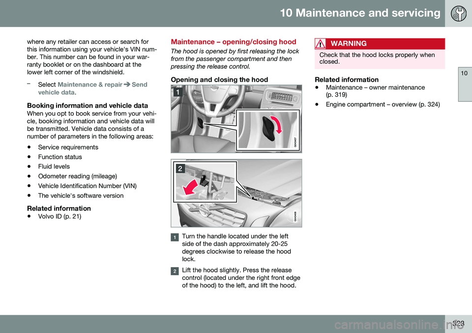
Opening and closing the hood
Turn the handle located under the left side of the dash approximately 20-25degrees clockwise to release the hoodlock.
Lift the hood slightly. Press the release control (located under the right front edgeof the hood) to the left, and lift the hood.
WARNING
Check that the hood locks properly when closed.
Related information
•Maintenance – owner maintenance (p. 319)
• Engine compartment – overview (p. 324)
Page 335 of 392
10 Maintenance and servicing
10
333
Bulbs – low beam, Halogen
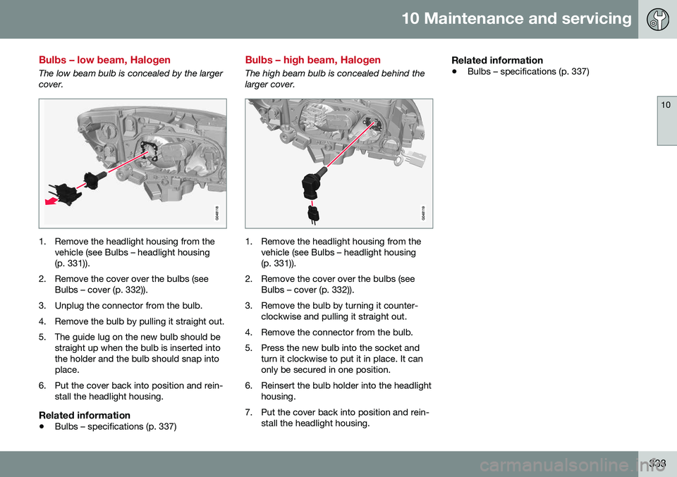
The low beam bulb is concealed by the larger cover.
1. Remove the headlight housing from thevehicle (see Bulbs – headlight housing (p. 331)).
2. Remove the cover over the bulbs (see Bulbs – cover (p. 332)).
3. Unplug the connector from the bulb.
4. Remove the bulb by pulling it straight out.
5. The guide lug on the new bulb should be straight up when the bulb is inserted into the holder and the bulb should snap intoplace.
6. Put the cover back into position and rein- stall the headlight housing.
Related information
• Bulbs – specifications (p. 337)
Bulbs – high beam, Halogen
The high beam bulb is concealed behind the larger cover.
1. Remove the headlight housing from the
vehicle (see Bulbs – headlight housing (p. 331)).
2. Remove the cover over the bulbs (see Bulbs – cover (p. 332)).
3. Remove the bulb by turning it counter- clockwise and pulling it straight out.
4. Remove the connector from the bulb.
5. Press the new bulb into the socket and turn it clockwise to put it in place. It can only be secured in one position.
6. Reinsert the bulb holder into the headlight housing.
7. Put the cover back into position and rein- stall the headlight housing.
Related information
• Bulbs – specifications (p. 337)
Page 336 of 392
10 Maintenance and servicing
10
334
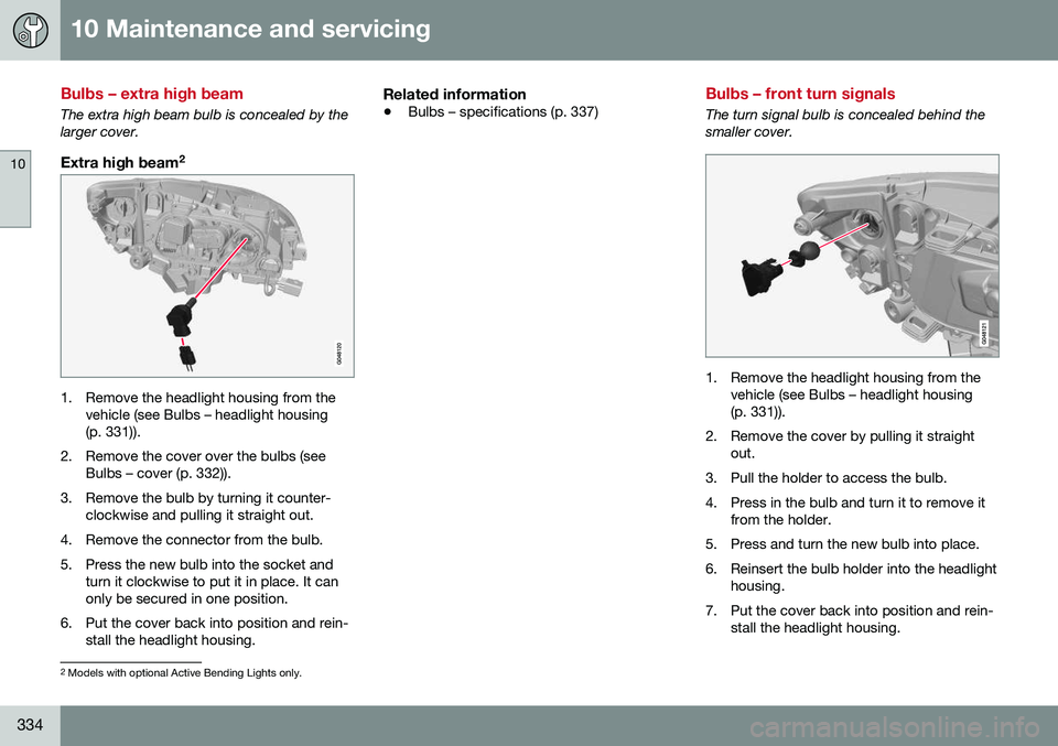
Bulbs – extra high beam
The extra high beam bulb is concealed by the larger cover.
Extra high beam2
1. Remove the headlight housing from the
vehicle (see Bulbs – headlight housing (p. 331)).
2. Remove the cover over the bulbs (see Bulbs – cover (p. 332)).
3. Remove the bulb by turning it counter- clockwise and pulling it straight out.
4. Remove the connector from the bulb.
5. Press the new bulb into the socket and turn it clockwise to put it in place. It can only be secured in one position.
6. Put the cover back into position and rein- stall the headlight housing.
Related information
• Bulbs – specifications (p. 337)
Bulbs – front turn signals
The turn signal bulb is concealed behind the smaller cover.
1. Remove the headlight housing from the
vehicle (see Bulbs – headlight housing (p. 331)).
2. Remove the cover by pulling it straight out.
3. Pull the holder to access the bulb.
4. Press in the bulb and turn it to remove it from the holder.
5. Press and turn the new bulb into place.
6. Reinsert the bulb holder into the headlight housing.
7. Put the cover back into position and rein- stall the headlight housing.
2Models with optional Active Bending Lights only.
Page 337 of 392
10 Maintenance and servicing
10
335
Related information
•Bulbs – specifications (p. 337)
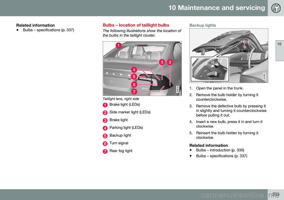
Bulbs – location of taillight bulbs
The following illustrations show the location of the bulbs in the taillight cluster.
Taillight lens, right side
Brake light (LEDs)
Side marker light (LEDs)
Brake light
Parking light (LEDs)
Backup light
Turn signal
Rear fog light
Backup lights
1. Open the panel in the trunk.
2. Remove the bulb holder by turning it
counterclockwise.
3. Remove the defective bulb by pressing it in slightly and turning it counterclockwise before pulling it out.
4. Insert a new bulb, press it in and turn it clockwise.
5. Reinsert the bulb holder by turning it clockwise.
Related information
• Bulbs – introduction (p. 330)
• Bulbs – specifications (p. 337)
Page 338 of 392
10 Maintenance and servicing
10
336
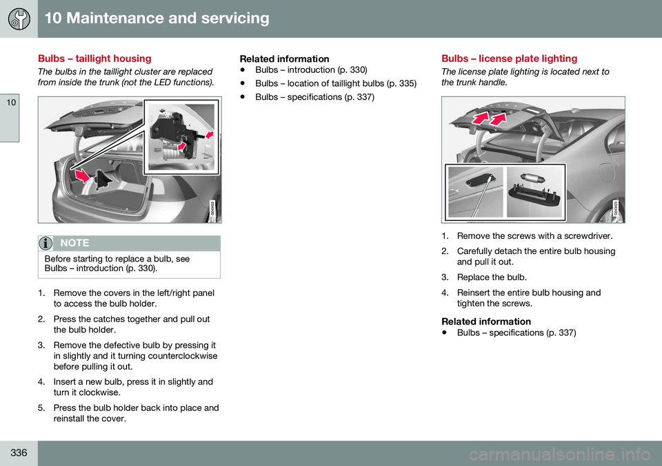
Bulbs – taillight housing
The bulbs in the taillight cluster are replaced from inside the trunk (not the LED functions).
NOTE
Before starting to replace a bulb, see Bulbs – introduction (p. 330).
1. Remove the covers in the left/right panelto access the bulb holder.
2. Press the catches together and pull out the bulb holder.
3. Remove the defective bulb by pressing it in slightly and it turning counterclockwise before pulling it out.
4. Insert a new bulb, press it in slightly and turn it clockwise.
5. Press the bulb holder back into place and reinstall the cover.
Related information
• Bulbs – introduction (p. 330)
• Bulbs – location of taillight bulbs (p. 335)
• Bulbs – specifications (p. 337)
Bulbs – license plate lighting
The license plate lighting is located next to the trunk handle.
1. Remove the screws with a screwdriver.
2. Carefully detach the entire bulb housing
and pull it out.
3. Replace the bulb.
4. Reinsert the entire bulb housing and tighten the screws.
Related information
• Bulbs – specifications (p. 337)
Page 383 of 392
12 Index
12
381
ISOFIX/LATCH anchors........................ 55
top tether anchors................................ 56
Child safety................................................ 46 booster cushions.................................. 54
child restraint systems.......................... 47
convertible seats.................................. 51
infant seats........................................... 49
Child safety locks...................................... 57
City safety........................................ 190, 191
Climate system........................................ 125 air distribution..................... 121, 126, 128
air vents.............................................. 121
Interior Air Quality System.................. 119
introduction......................................... 118
passenger compartment filter............ 119
refrigerant........................................... 118
Clock, setting............................................. 72
Cold weather driving................................ 272
Collision warning system.. 197, 199, 202, 203, 205, 206
Compass in rearview mirror....................... 99
Connected service booking..................... 321
Conserving electrical current................... 271
Convertible seats....................................... 51
Coolant............................................ 327, 373
Cooling system, general information....... 271
Corner traction control............................. 163 Courtesy lighting........................................ 89
Crash event data....................................... 18
Crash mode......................................... 44, 45
Cruise control.................................. 169, 171
adaptive.............................................. 172
Curb weight............................................. 298
Current, conserving................................. 271
Cyclist detection.............................. 201, 205
D
Daytime running lights............................... 82
Defroster.................................................. 125
Detachable key blade...................... 144, 145Disconnecting the front passenger’s air-
bag............................................................. 36
Distance Alert.......................................... 186
Dome lighting............................................. 89
Door mirrors......................................... 96, 97
Driver alert....................... 210, 211, 212, 213 Lane Departure Warning..... 215, 216,
217, 218Lane Keeping Aid....... 220, 221, 223, 224
Driver distraction warning.......................... 23
Driving economically................................ 277 Driving in cold weather............................ 272
Driving through water.............................. 270
E
ECC................................................. 123, 124
Eco (driving function)............................... 260
Eco coast................................................. 260
Eco guide................................................... 65
Economical driving.................................. 277
Electrically heated steering wheel............. 82
Electrical sockets..................................... 133
Electric parking brake.............. 266, 267, 269
Electronic Climate Control............... 122, 124
air distribution table............................ 128
Interior Air Quality System.................. 120
Electronic oil level sensor........................ 326
Electronic stability control....................... 162
Emergency locking retractor...................... 47
Emergency starting.................................. 249
Emergency towing................... 281, 282, 283
Emission inspection readiness................ 321Engine overheating........................................... 69
specifications...................................... 370