color VOLVO S60 2016 Owner´s Manual
[x] Cancel search | Manufacturer: VOLVO, Model Year: 2016, Model line: S60, Model: VOLVO S60 2016Pages: 392, PDF Size: 10.04 MB
Page 106 of 392
||
03 Instruments and controls
03
104
2. Simultaneously press and hold both thechosen HomeLink and hand-held trans- mitter buttons until the HomeLink indica-tor light changes from a slow to a rapidlyblinking light. Now you may release boththe HomeLink and hand-held transmitterbuttons.
NOTE
Some devices may require you to replace this Programming Step 2 with proceduresnoted in the “Gate Operator / CanadianProgramming” section. If the HomeLinkindicator light does not change to a rapidlyblinking light after performing these steps,contact HomeLink at www.homelink.com/www.youtube.com/HomeLinkGentex or byphoning the hotline at 1–800–355–3515.
3. Firmly press, hold for five seconds and
release the programmed HomeLink but-
ton up to two separate times to activate the door. If the door does not activate,press and hold the just-trained HomeLinkbutton and observe the indicator light.
• If the indicator light
stays on con-
stantly, programming is complete and your device should activate when the HomeLink button is pressed andreleased.
• If the indicator light blinks
rapidly for
two seconds and then turns to aconstant light continue with “Pro- gramming” steps 4-6 to complete the
programming of a rolling code equip- ped device (most commonly a garagedoor opener).
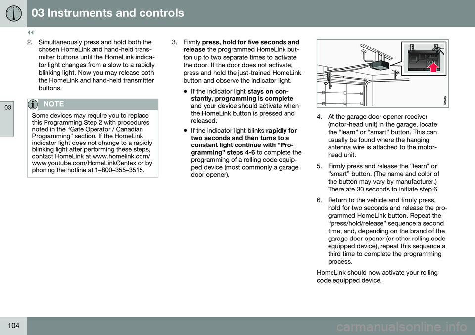
4. At the garage door opener receiver
(motor-head unit) in the garage, locate the “learn” or “smart” button. This canusually be found where the hangingantenna wire is attached to the motor-head unit.
5. Firmly press and release the “learn” or “smart” button. (The name and color ofthe button may vary by manufacturer.)There are 30 seconds to initiate step 6.
6. Return to the vehicle and firmly press, hold for two seconds and release the pro-grammed HomeLink button. Repeat the“press/hold/release” sequence a secondtime, and, depending on the brand of thegarage door opener (or other rolling codeequipped device), repeat this sequence athird time to complete the programmingprocess.
HomeLink should now activate your rollingcode equipped device.
Page 109 of 392
03 Instruments and controls
03
* Option/accessory, for more information, see Introduction.107
Information display – menu controls
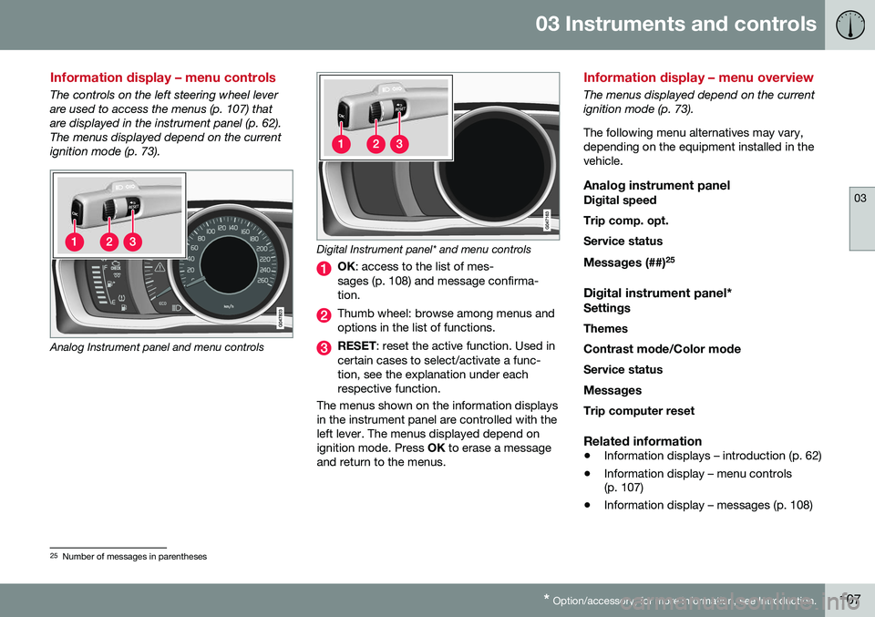
The controls on the left steering wheel lever are used to access the menus (p. 107) thatare displayed in the instrument panel (p. 62).The menus displayed depend on the currentignition mode (p. 73).
Analog Instrument panel and menu controls
Digital Instrument panel* and menu controls
OK : access to the list of mes-
sages (p. 108) and message confirma- tion.
Thumb wheel: browse among menus and options in the list of functions.
RESET : reset the active function. Used in
certain cases to select/activate a func- tion, see the explanation under eachrespective function.
The menus shown on the information displaysin the instrument panel are controlled with theleft lever. The menus displayed depend onignition mode. Press OK to erase a message
and return to the menus.
Information display – menu overview
The menus displayed depend on the current ignition mode (p. 73). The following menu alternatives may vary, depending on the equipment installed in thevehicle.
Analog instrument panelDigital speed Trip comp. opt.Service status
Messages (##) 25
Digital instrument panel*
Settings
Themes
Contrast mode /Color mode
Service status
Messages Trip computer reset
Related information
• Information displays – introduction (p. 62)
• Information display – menu controls (p. 107)
• Information display – messages (p. 108)
25
Number of messages in parentheses
Page 113 of 392
03 Instruments and controls
03
}}
111
FunctionDescription
Digital speed – km/h – mph– NoneThis displays the vehicle's speed digitally in the center of the instrument panel
• Open by pressing
OK, scroll using the thumb wheel, confirm by pressing OK and exit by pressing
ENTER .
Trip comp. opt.
–
Distance to empty
– Fuel consumption
– Average speed
– Trip odometer T1 and total dist.
– Trip odometer T2 and total dist.
Selections among the trip computer information headings are made here. The symbols that have already been selected have a check mark and are displayed in white. Those not selected are not checked and
are displayed in gray:
1. Open the function by pressing OK and scroll to the desired heading using the thumb wheel.
2. Confirm by pressing OK. The symbol will change colors from gray to white and will be checked.
3. Continue this procedure or exit by pressing RESET.
Service statusShows the number of months and mileage until the next scheduled service.
Messages (##)For additional information, see Information display – menu controls (p. 107).
Information headingsAny of the information headings in the follow- ing table can be displayed. To do so:
1. Ensure that none of the trip computer
controls are being used in a command sequence; reset them by pressing RESET
twice. 2. Turn the
thumb wheel to begin display-
ing the information headings. Stop on thedesired heading.
3. See the table for an explanation of the heading or the actions that can be taken.
Page 116 of 392
||
03 Instruments and controls
03
114
FunctionDescription
Contrast mode/Color modeAdjust the instrument panel's contrast and color.
Service statusShows the number of months and mileage until the next scheduled service.
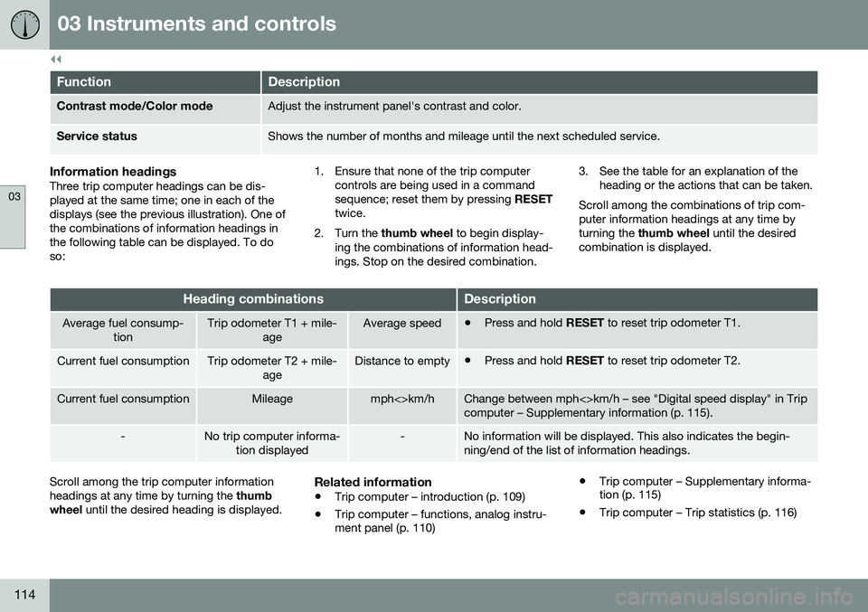
Information headingsThree trip computer headings can be dis- played at the same time; one in each of thedisplays (see the previous illustration). One ofthe combinations of information headings inthe following table can be displayed. To doso: 1. Ensure that none of the trip computer
controls are being used in a commandsequence; reset them by pressing RESET
twice.
2. Turn the thumb wheel to begin display-
ing the combinations of information head-ings. Stop on the desired combination. 3. See the table for an explanation of the
heading or the actions that can be taken.
Scroll among the combinations of trip com-puter information headings at any time byturning the thumb wheel until the desired
combination is displayed.
Heading combinationsDescription
Average fuel consump- tionTrip odometer T1 + mile- ageAverage speed•Press and hold
RESET to reset trip odometer T1.
Current fuel consumptionTrip odometer T2 + mile-
ageDistance to empty•Press and hold
RESET to reset trip odometer T2.
Current fuel consumptionMileagemph<>km/hChange between mph<>km/h – see "Digital speed display" in Trip computer – Supplementary information (p. 115).
-No trip computer informa-
tion displayed-No information will be displayed. This also indicates the begin- ning/end of the list of information headings.
Scroll among the trip computer information headings at any time by turning the thumb
wheel until the desired heading is displayed.Related information
•Trip computer – introduction (p. 109)
• Trip computer – functions, analog instru- ment panel (p. 110) •
Trip computer – Supplementary informa-tion (p. 115)
• Trip computer – Trip statistics (p. 116)
Page 178 of 392
07 Driver support
07
176
Adaptive Cruise Control – setting speed
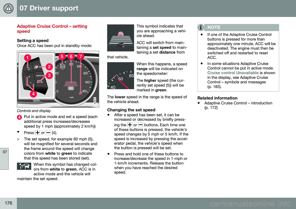
Setting a speedOnce ACC has been put in standby mode:
Controls and display
Put in active mode and set a speed (each additional press increases/decreasesspeed by 1 mph (approximately 2 km/h))
• Press
or (4).
> The set speed, for example 60 mph (5), will be magnified for several seconds and the frame around the speed will changecolors from white to green to indicate
that this speed has been stored (set).
When this symbol has changed col-ors from white to green , ACC is in
active mode and the vehicle will
maintain the set speed.
This symbol indicates that you are approaching a vehi-cle ahead. ACC will switch from main- taining a set speed to main-
taining a set distance from
that vehicle.
When this happens, a speed range will be indicated on
the speedometer: The higher speed (the cur-
rently set speed (5)) will be marked in green.
The lower speed in the range is the speed of
the vehicle ahead.
Changing the set speed
• After a speed has been set, it can be increased or decreased by briefly press- ing the
or buttons. Each time one
of these buttons is pressed, the vehicle's speed changes by 5 mph or 5 km/h. If thespeed is increased by pressing the accel-erator pedal, the vehicle's speed whenthe button is pressed will be set.
• Press and hold one of these buttons toincrease/decrease the speed in 1-mph or1-km/h increments. Release the buttonwhen you have reached the desiredspeed.
NOTE
•If one of the Adaptive Cruise Control buttons is pressed for more thanapproximately one minute, ACC will bedeactivated. The engine must then beswitched off and restarted to resetACC.
• In some situations Adaptive CruiseControl cannot be put in active mode.
Cruise control Unavailable is shown
in the display, see Adaptive Cruise Control – symbols and messages(p. 183).
Related information
• Adaptive Cruise Control – introduction (p. 172)
Page 179 of 392
07 Driver support
07
}}
177
Adaptive Cruise Control – setting time interval
Setting a time interval
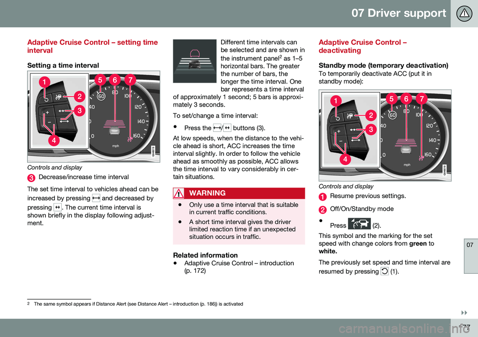
Controls and display
Decrease/increase time interval
The set time interval to vehicles ahead can be increased by pressing
and decreased by
pressing
. The current time interval is
shown briefly in the display following adjust- ment. Different time intervals canbe selected and are shown in the instrument panel
2
as 1–5
horizontal bars. The greater the number of bars, thelonger the time interval. Onebar represents a time interval
of approximately 1 second; 5 bars is approxi-mately 3 seconds.
To set/change a time interval:
• Press the
/ buttons (3).
At low speeds, when the distance to the vehi- cle ahead is short, ACC increases the timeinterval slightly. In order to follow the vehicleahead as smoothly as possible, ACC allowsthe time interval to vary considerably in cer-tain situations.
WARNING
• Only use a time interval that is suitable in current traffic conditions.
• A short time interval gives the driverlimited reaction time if an unexpectedsituation occurs in traffic.
Related information
•
Adaptive Cruise Control – introduction (p. 172)
Adaptive Cruise Control – deactivating
Standby mode (temporary deactivation)To temporarily deactivate ACC (put it in standby mode):
Controls and display
Resume previous settings.
Off/On/Standby mode
• Press
(2).
This symbol and the marking for the set speed with change colors from green to
white. The previously set speed and time interval are resumed by pressing
(1).
2 The same symbol appears if Distance Alert (see Distance Alert – introduction (p. 186)) is activated
Page 239 of 392
07 Driver support
07
237
WARNING
Keep in mind that the image on the screen only shows the area behind the vehicle.The driver must always watch for people,animals, other vehicles, etc., near the sidesof the vehicle when turning while backingup.
Marker lines
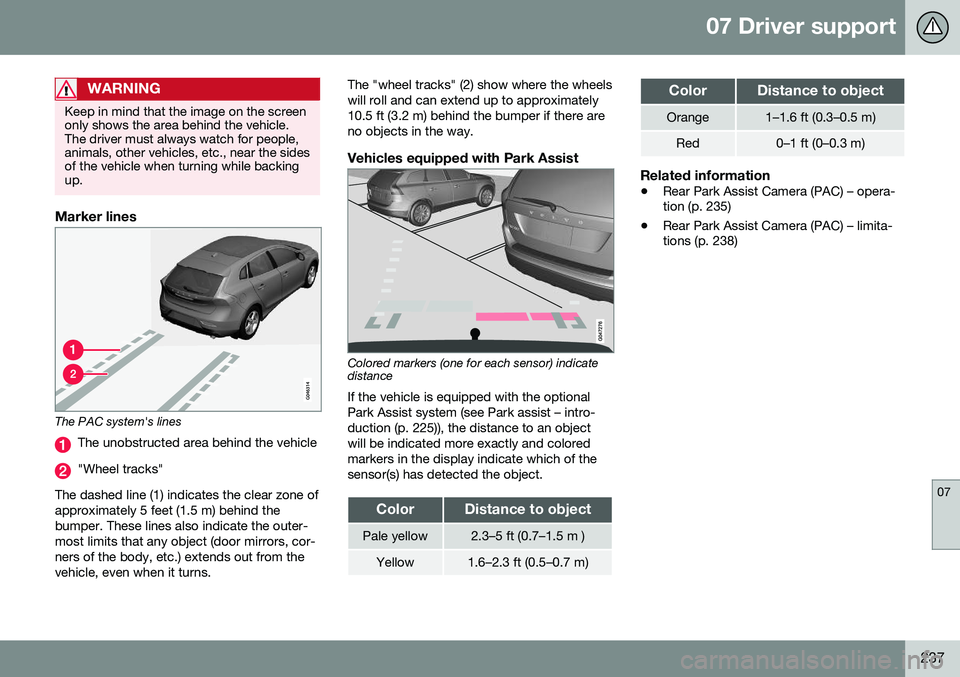
The PAC system's lines
The unobstructed area behind the vehicle
"Wheel tracks"
The dashed line (1) indicates the clear zone of approximately 5 feet (1.5 m) behind thebumper. These lines also indicate the outer-most limits that any object (door mirrors, cor-ners of the body, etc.) extends out from thevehicle, even when it turns. The "wheel tracks" (2) show where the wheelswill roll and can extend up to approximately10.5 ft (3.2 m) behind the bumper if there areno objects in the way.
Vehicles equipped with Park Assist
Colored markers (one for each sensor) indicate distance If the vehicle is equipped with the optional Park Assist system (see Park assist – intro-duction (p. 225)), the distance to an objectwill be indicated more exactly and coloredmarkers in the display indicate which of thesensor(s) has detected the object.
ColorDistance to object
Pale yellow2.3–5 ft (0.7–1.5 m )
Yellow1.6–2.3 ft (0.5–0.7 m)
ColorDistance to object
Orange1–1.6 ft (0.3–0.5 m)
Red0–1 ft (0–0.3 m)
Related information
•
Rear Park Assist Camera (PAC) – opera- tion (p. 235)
• Rear Park Assist Camera (PAC) – limita-tions (p. 238)
Page 277 of 392
08 Starting and driving
08
}}
275
WARNING
Never carry a cell phone that is switched
on while refueling your vehicle. If the
phone rings, this may cause a spark that could ignite gasoline fumes, resulting infire and injury.
WARNING
Carbon monoxide is a poisonous, color- less, and odorless gas. It is present in allexhaust gases. If you ever smell exhaustfumes inside the vehicle, make sure thepassenger compartment is ventilated, andimmediately return the vehicle to a trainedand qualified Volvo service technician forcorrection.
Related information
• Refueling – fuel requirements (p. 273)
Refueling – opening/closing fuel filler door
The fuel filler door is located on the right rear fender (indicated by an arrow beside the fuel tank symbol on the information display
)
With the ignition switched off, press and release the button on the lighting panel tounlock the fuel filler door. Please note that thefuel filler door will remain unlocked until thevehicle begins to move forward. An audibleclick will be heard when the fuel filler doorrelocks. •If you intend to leave your vehicle while it is being refueled, this feature enables youto lock the doors/trunk while leaving thefuel filler door unlocked.
• You can also keep the vehicle locked ifyou remain inside it during refueling. Thecentral locking button does not lock thefuel filler door. •
Be sure the fuel filler door is not obstruc-ted and is completely closed after refuel-ing.
• Open the fuel filler cap slowly during hotweather.
Close the fuel filler door by pressing it; a click indicates that it is closed.
CAUTION
Avoid spilling gasoline during refueling. In addition to causing damage to the environ-ment, gasolines containing alcohol cancause damage to painted surfaces, whichmay not be covered under the New VehicleLimited Warranty.
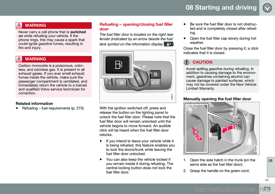
Manually opening the fuel filler door
1. Open the side hatch in the trunk (on the same side as the fuel filler door).
2. Grasp the handle on the green cord.
Page 288 of 392
09 Wheels and tires
09
286
Tires – storage and age
When storing complete wheels (tires mounted on rims), they should be suspended off thefloor or placed on their sides on the floor.
New Tires
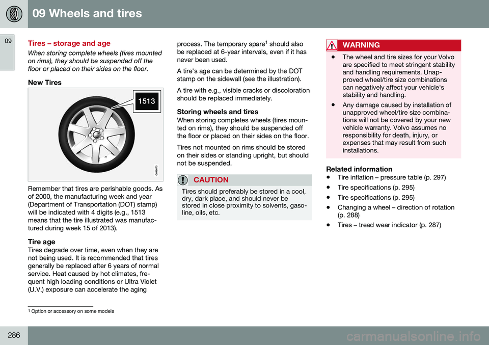
Remember that tires are perishable goods. Asof 2000, the manufacturing week and year(Department of Transportation (DOT) stamp)will be indicated with 4 digits (e.g., 1513means that the tire illustrated was manufac-tured during week 15 of 2013).
Tire ageTires degrade over time, even when they are not being used. It is recommended that tiresgenerally be replaced after 6 years of normalservice. Heat caused by hot climates, fre-quent high loading conditions or Ultra Violet(U.V.) exposure can accelerate the agingprocess. The temporary spare
1
should also
be replaced at 6-year intervals, even if it hasnever been used. A tire's age can be determined by the DOT stamp on the sidewall (see the illustration). A tire with e.g., visible cracks or discoloration should be replaced immediately.
Storing wheels and tiresWhen storing completes wheels (tires moun-ted on rims), they should be suspended offthe floor or placed on their sides on the floor. Tires not mounted on rims should be stored on their sides or standing upright, but shouldnot be suspended.
CAUTION
Tires should preferably be stored in a cool, dry, dark place, and should never bestored in close proximity to solvents, gaso-line, oils, etc.
WARNING
• The wheel and tire sizes for your Volvo are specified to meet stringent stabilityand handling requirements. Unap-proved wheel/tire size combinationscan negatively affect your vehicle'sstability and handling.
• Any damage caused by installation ofunapproved wheel/tire size combina-tions will not be covered by your newvehicle warranty. Volvo assumes noresponsibility for death, injury, orexpenses that may result from suchinstallations.
Related information
•
Tire inflation – pressure table (p. 297)
• Tire specifications (p. 295)
• Tire specifications (p. 295)
• Changing a wheel – direction of rotation (p. 288)
• Tires – tread wear indicator (p. 287)
1
Option or accessory on some models
Page 310 of 392
09 Wheels and tires
09
308
Calibrating Tire Monitor
In order for Tire Monitor to work correctly, tire pressure reference values must be set. Thismust be done each time wheels or tire pres-sures are changed.
Calibration1. Switch off the engine.
2. Inflate the tires to the desired pressure(consult tire pressure placard located on the driver's side B-pillar (the structuralmember at the side of the vehicle) andput the ignition in mode II, see Ignition
modes (p. 73).
3. Press the MY CAR button on the center
console control panel and select
Settings
Car settingsTire monitoring.
4. Press OK/MENU , select
Calibrate tire
pressure and press OK/MENU again.
5. Drive away. > The calibration process will be comple-ted while driving and will be interrupted if the vehicle is parked and the engineis switched off. Calibration continuesautomatically when driving resumes.The system will not give any confirma-tion when calibration is finishedalthough it will state if calibration fails.
The new reference values will be used untilsteps 1-5 stated above are repeated.
NOTE
Always remember to calibrate Tire Monitor when the wheels have been changed orthe tire pressure has been correctedaccording to tire pressure placard or tirepressure table. If correct reference valueshave not been set, the system cannotissue low tire pressure alerts correctly.
Tire Monitor status information
The current status of the system and the tires is indicated by color-coded graphics. This status can be displayed by pressing the MY CAR button on the center console and
going to
SettingsCar settingsTire
monitoring.
The following color-coded graphics indicate:
• All green
: the system is operational and
all tire pressures are at or above the rec- ommended levels.
• One yellow wheel
: the tire indicated is
under-inflated.
• All wheels yellow
: two or more tires are
under-inflated
• All wheels gray
: the system is currently
unavailable. It might be necessary todrive at a speed of at least 20 mph(30 km/h) for several minutes for the sys-tem to become operational.
• All wheels gray in combination with the message
Tire press. syst Service
required and the telltale in the instru-
ment panel (
) is illuminated : the
system is not functioning correctly. Have it checked by a trained and qualifiedVolvo service technician.
• All wheels gray in combination with the message
Tire press. syst currently
unavailable and the telltale in the
instrument panel (
) is illuminated :