brake sensor VOLVO S60 2017 Owner´s Manual
[x] Cancel search | Manufacturer: VOLVO, Model Year: 2017, Model line: S60, Model: VOLVO S60 2017Pages: 398, PDF Size: 9.46 MB
Page 202 of 398
DRIVER SUPPORT
200
City Safety – symbols and messages
Symbols and messages in the display
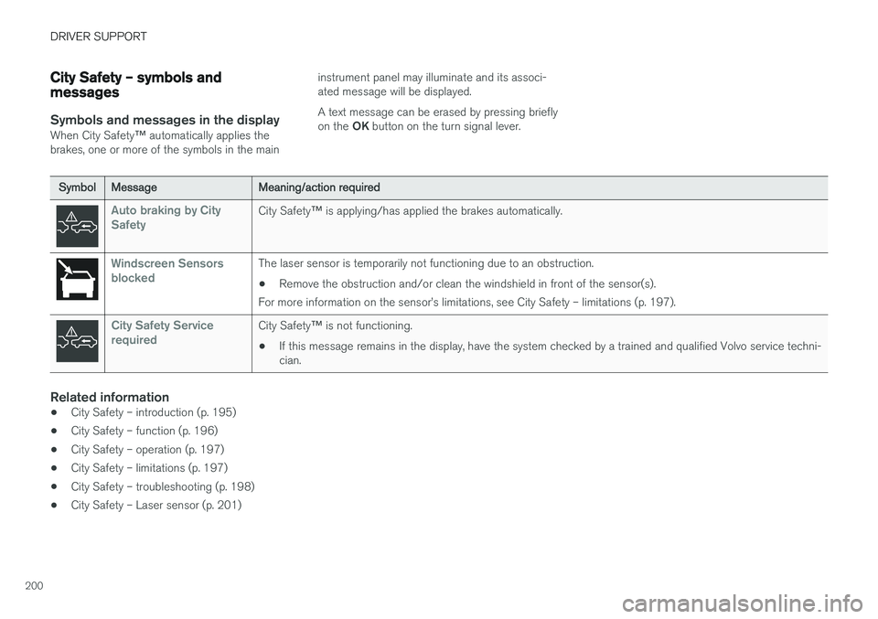
When City Safety™ automatically applies the
brakes, one or more of the symbols in the main instrument panel may illuminate and its associ- ated message will be displayed. A text message can be erased by pressing briefly on the
OK button on the turn signal lever.
SymbolMessageMeaning/action required
Auto braking by City SafetyCity Safety ™ is applying/has applied the brakes automatically.
Windscreen Sensors blockedThe laser sensor is temporarily not functioning due to an obstruction.
• Remove the obstruction and/or clean the windshield in front of the sensor(s).
For more information on the sensor
Page 206 of 398
DRIVER SUPPORT
* Option/accessory, for more information, see Introduction.
204
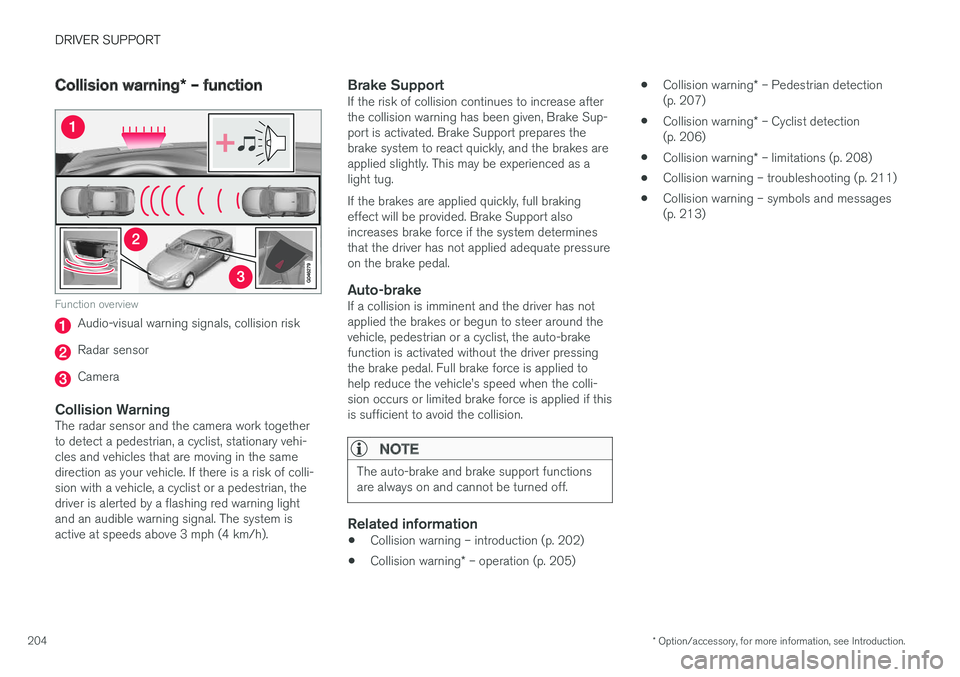
Collision warning * – function
Function overview
Audio-visual warning signals, collision risk
Radar sensor
Camera
Collision WarningThe radar sensor and the camera work together to detect a pedestrian, a cyclist, stationary vehi-cles and vehicles that are moving in the samedirection as your vehicle. If there is a risk of colli-sion with a vehicle, a cyclist or a pedestrian, thedriver is alerted by a flashing red warning lightand an audible warning signal. The system isactive at speeds above 3 mph (4 km/h).
Brake SupportIf the risk of collision continues to increase afterthe collision warning has been given, Brake Sup-port is activated. Brake Support prepares thebrake system to react quickly, and the brakes areapplied slightly. This may be experienced as alight tug. If the brakes are applied quickly, full braking effect will be provided. Brake Support alsoincreases brake force if the system determinesthat the driver has not applied adequate pressureon the brake pedal.
Auto-brakeIf a collision is imminent and the driver has notapplied the brakes or begun to steer around thevehicle, pedestrian or a cyclist, the auto-brakefunction is activated without the driver pressingthe brake pedal. Full brake force is applied tohelp reduce the vehicle
Page 211 of 398
DRIVER SUPPORT
* Option/accessory, for more information, see Introduction.209
WARNING
•In certain situations, the system cannot provide warnings or warnings may bedelayed if traffic conditions or other exter-nal factors make it impossible for theradar sensor or camera to detect apedestrian, a cyclist or a vehicle ahead.
• Warnings may not be provided if the dis-tance to the vehicle ahead is short, or ifmovements of the steering wheel/brakepedal are great, such as during activedriving.
• The sensor system has a limited range forpedestrians/cyclists and provides warn-ings and braking effect most effectively atspeeds up to 30 mph (50 km/h). For sta-tionary or slow-moving vehicles, the sys-tem functions best if your vehicle
Page 213 of 398
DRIVER SUPPORT
}}
211
Collision warning – troubleshooting
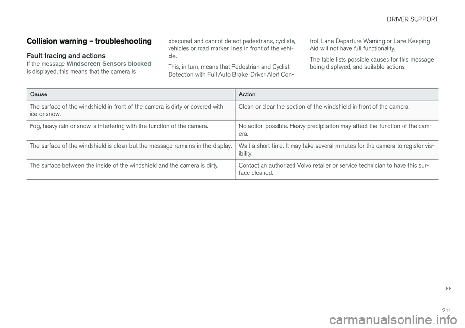
Fault tracing and actionsIf the message Windscreen Sensors blockedis displayed, this means that the camera isobscured and cannot detect pedestrians, cyclists, vehicles or road marker lines in front of the vehi-cle. This, in turn, means that Pedestrian and Cyclist Detection with Full Auto Brake, Driver Alert Con-trol, Lane Departure Warning or Lane KeepingAid will not have full functionality. The table lists possible causes for this message being displayed, and suitable actions.
CauseAction
The surface of the windshield in front of the camera is dirty or covered with ice or snow.Clean or clear the section of the windshield in front of the camera.
Fog, heavy rain or snow is interfering with the function of the camera.No action possible. Heavy precipitation may affect the function of the cam- era.
The surface of the windshield is clean but the message remains in the display.Wait a short time. It may take several minutes for the camera to register vis- ibility.
The surface between the inside of the windshield and the camera is dirty.Contact an authorized Volvo retailer or service technician to have this sur- face cleaned.
Page 235 of 398
DRIVER SUPPORT
}}
* Option/accessory, for more information, see Introduction.233
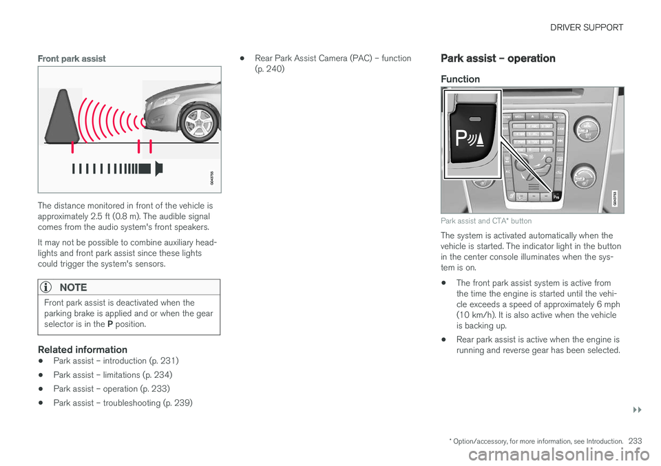
Front park assist
The distance monitored in front of the vehicle is approximately 2.5 ft (0.8 m). The audible signalcomes from the audio system's front speakers. It may not be possible to combine auxiliary head- lights and front park assist since these lightscould trigger the system's sensors.
NOTE
Front park assist is deactivated when the parking brake is applied and or when the gear selector is in the P position.
Related information
• Park assist – introduction (p. 231)
• Park assist – limitations (p. 234)
• Park assist – operation (p. 233)
• Park assist – troubleshooting (p. 239) •
Rear Park Assist Camera (PAC) – function (p. 240)
Park assist – operation
Function
Park assist and CTA
* button
The system is activated automatically when the vehicle is started. The indicator light in the buttonin the center console illuminates when the sys-tem is on. • The front park assist system is active from the time the engine is started until the vehi-cle exceeds a speed of approximately 6 mph(10 km/h). It is also active when the vehicleis backing up.
• Rear park assist is active when the engine isrunning and reverse gear has been selected.
Page 236 of 398
||
DRIVER SUPPORT
234
Activating/deactivating
The system is activated automatically when the vehicle is started.
–Press the Park assist button on the center console to temporarily deactivate the sys-tem(s).
> The indicator light in the button will go outwhen the system has been deactivated.
Park assist will be automatically reactivated the next time the engine is started, or if the button ispressed (the indicator light in the button will illu-minate).
NOTE
Park assist is disengaged automatically when the parking brake is applied.
Related information
• Park assist – introduction (p. 231)
• Park assist – limitations (p. 234)
• Park assist – function (p. 231)
• Park assist – troubleshooting (p. 239)
• Rear Park Assist Camera (PAC) – function (p. 240)
Park assist – limitations
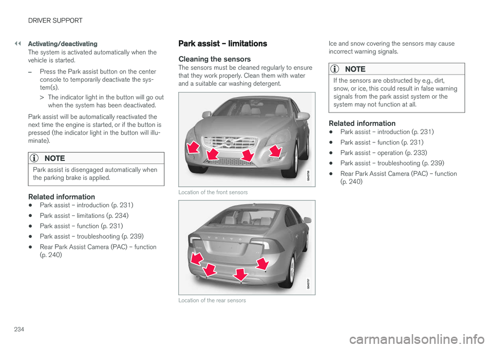
Cleaning the sensorsThe sensors must be cleaned regularly to ensure that they work properly. Clean them with waterand a suitable car washing detergent.
Location of the front sensors
Location of the rear sensors
Ice and snow covering the sensors may cause incorrect warning signals.
NOTE
If the sensors are obstructed by e.g., dirt, snow, or ice, this could result in false warningsignals from the park assist system or thesystem may not function at all.
Related information
•Park assist – introduction (p. 231)
• Park assist – function (p. 231)
• Park assist – operation (p. 233)
• Park assist – troubleshooting (p. 239)
• Rear Park Assist Camera (PAC) – function (p. 240)
Page 240 of 398
DRIVER SUPPORT
* Option/accessory, for more information, see Introduction.
238
Park Assist Pilot (PAP) * – limitations
The PAP parking procedure will be cancelled if.
• The vehicle's speed goes above approxi- mately 4 mph 7 km/h
• The driver moves the steering wheel
• If the stability or ABS systems are activated(e.g., if a wheel starts to spin because of aslippery road surface
If the system has been switched off, this will beindicated by a text message in the instrumentpanel.
NOTE
• PAP will not function correctly if its sen- sors are obstructed by dirt, snow, etc.
• In certain situations, PAP may not be ableto measure a parking space. This couldbe due to external sources of sound (e.g.,a vehicle's horn, tires on wet asphalt,pneumatic brakes, noise from a motorcy-cle's exhaust, etc.) emitting ultrasoundusing approximately the same frequen-cies as PAP.
Information to keep in mind
PAP is only intended to provide parallel parking assistance but may not be able to function fully inall situations. •
PAP's function is based on the way that thevehicles are parked behind and in front ofyour parking space. If they are, for example,parked too close to the curb, there is a riskthat your vehicle's tires or wheel rims couldbe damaged by the curb during the parkingprocedure.
• PAP is intended to provide parking assis-tance on straight streets, not sections ofstreet with curved or irregular curbs. Be surethat your vehicle is parallel to the curb whenPAP measures the parking space.
• PAP may not be able to provide parkingassistance on narrow streets due to lack ofspace to maneuver the vehicle. In situationslike this, it may help to drive as close to theside of the road as possible where the park-ing space is located.
• Use only approved tires with the correct infla-tion pressure because this affects PAP'scapacity to provide parking assistance.Changing to a different approved tire sizemay affect PAP's parameters. Consult atrained and qualified Volvo service technician.
• Heavy rain or snow may inhibit PAP'scapacity to correctly measure a parkingspace.
• Do not use PAP if snow chains or a tempo-rary spare tire is being used.
• Do not use PAP if there are any objects pro-truding from the vehicle.
WARNING
• The front end of your vehicle may turn out toward oncoming traffic during the park-ing procedure.
• Objects located above the parking sen-sors' field of vision are not included whenPAP measures a parking space. For thisreason, PAP may turn into the parkingspace too soon. Avoid parking spaces ofthis type.
• The driver is always responsible for deter-mining if PAP has selected a suitableparking space.
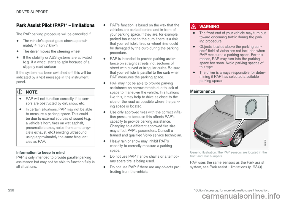
Maintenance
Generic illustration. The PAP sensors are located in the front and rear bumpers
PAP uses the same sensors as the Park assist system, see Park assist – limitations (p. 234)).
Page 241 of 398
DRIVER SUPPORT
* Option/accessory, for more information, see Introduction.239
The sensors must be cleaned regularly to ensure that they work properly. Clean them with waterand a suitable car washing detergent.
Related information
•
Park Assist Pilot (PAP)
* – introduction
(p. 235)
• Park Assist Pilot (PAP)
* – function (p. 235)
• Park Assist Pilot (PAP)
* – operation (p. 236)
• Park Assist Pilot (PAP)
* – symbols and mes-
sages (p. 239)
• Park assist – introduction (p. 231)
• Rear Park Assist Camera (PAC) – introduc-tion (p. 240)
Park Assist Pilot (PAP)
* – symbols
and messages
Various PAP-related combinations of symbols, graphics and text messages are displayed in theinstrument panel and sometimes also includesuitable actions. A text message can be erased by pressing briefly on the OK button on the turn signal lever.
Contact a Volvo retailer or a trained and qualified Volvo service technician If a message indicatingthat PAP is not functioning properly is displayed.
Related information
• Park Assist Pilot (PAP)
* – introduction
(p. 235)
• Park Assist Pilot (PAP)
* – function (p. 235)
• Park Assist Pilot (PAP)
* – operation (p. 236)
• Park Assist Pilot (PAP)
* – limitations (p. 238)
• Park assist – introduction (p. 231)
• Rear Park Assist Camera (PAC) – introduc-tion (p. 240)
Park assist – troubleshooting
Faults in the systemIf the information symbol illuminates and Park
assist syst Service required is shown on the
information display, this indicates that the system is not functioning properly and has been disen-gaged. Consult a trained and qualified Volvo serv-ice technician.
CAUTION
In certain circumstances, the park assist sys- tem may give unexpected warning signalsthat can be caused by external sound sourcesthat use the same ultrasound frequencies asthe system. This may include such things asthe horns of other vehicles, wet tires onasphalt, pneumatic brakes, motorcycleexhaust pipes, etc. This does not indicate afault in the system.
Related information
• Park assist – introduction (p. 231)
• Park assist – limitations (p. 234)
• Park assist – function (p. 231)
• Park assist – operation (p. 233)
• Rear Park Assist Camera (PAC) – function (p. 240)
Page 286 of 398
||
STARTING AND DRIVING
* Option/accessory, for more information, see Introduction.
284 nents, altering emission system components or location or removing components, and/orrepeated use of leaded fuel.
NOTE
Unleaded fuel is required for vehicles with three-way catalytic converters.
Heated oxygen sensorsThe heated oxygen sensors monitor the oxygen content of the exhaust gases. Readings are fedinto a control module that continuously monitorsengine functions and controls fuel injection. Theratio of fuel to air into the engine is continuouslyadjusted for efficient combustion to help reduceharmful emissions.
Related information
•
Information displays – warning symbols(p. 69)
• Engine and cooling system (p. 277)
Economical driving
Better driving economy may be obtained by thinking ahead, avoiding rapid starts and stopsand adjusting the speed of your vehicle to imme-diate traffic conditions.
Economical driving conserves natural
resources
Observe the following rules: • Bring the engine to normal operating tem- perature as soon as possible by driving witha light foot on the accelerator pedal for thefirst few minutes of operation. A cold engineuses more fuel and is subject to increasedwear.
• Whenever possible, avoid using the vehiclefor driving short distances. This does notallow the engine to reach normal operatingtemperature.
• Drive carefully and avoid rapid accelerationand hard braking.
• Use the transmission's Drive (
D) position as
often as possible and avoid using kick-down.
• Using the transmission's Sport mode 13
may
increase fuel consumption somewhat. Use the transmission's Drive ( D) position as often
as possible. For additional information about Sport mode, see Transmission – Geartronic(p. 258). •
Using the engine's optional Eco function canhelp improve fuel economy. For additional information, see ECO
* (p. 267).
• Do not exceed posted speed limits.
• Avoid carrying unnecessary items (extra load) in the vehicle.
• Maintain correct tire pressure. Check tirepressure regularly (when tires are cold).
• Remove snow tires when threat of snow orice has ended.
• Note that roof racks, ski racks, etc, increaseair resistance and also fuel consumption.
• At highway driving speeds, fuel consumptionwill be lower with the air conditioning on andthe windows closed than with the air condi-tioning off and the windows open.
• Using the onboard trip computer's fuel con-sumption modes can help you learn how todrive more economically.
Other factors that decrease gas mileage are:
• Dirty air cleaner
• Dirty engine oil and clogged oil filter
• Dragging brakes
• Incorrect front end alignment
13
Certain models only.
Page 359 of 398
MAINTENANCE AND SERVICING
* Option/accessory, for more information, see Introduction.357
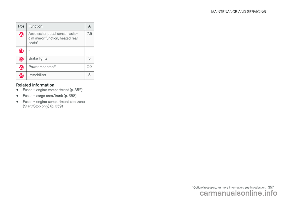
PosFunctionA
Accelerator pedal sensor, auto- dim mirror function, heated rear seats*7.5
-
Brake lights5
Power moonroof *20
Immobilizer5
Related information
•Fuses – engine compartment (p. 352)
• Fuses – cargo area/trunk (p. 358)
• Fuses – engine compartment cold zone (Start/Stop only) (p. 359)