display VOLVO S60 2018 Owner´s Manual
[x] Cancel search | Manufacturer: VOLVO, Model Year: 2018, Model line: S60, Model: VOLVO S60 2018Pages: 396, PDF Size: 9.4 MB
Page 333 of 396
MAINTENANCE AND SERVICING
* Option/accessory.331
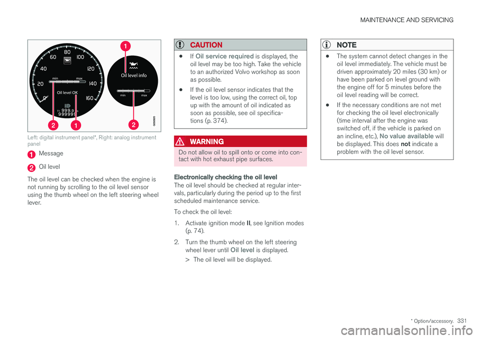
Left: digital instrument panel *, Right: analog instrument
panel
Message
Oil level
The oil level can be checked when the engine is not running by scrolling to the oil level sensorusing the thumb wheel on the left steering wheellever.
CAUTION
• If Oil service required is displayed, the
oil level may be too high. Take the vehicle to an authorized Volvo workshop as soonas possible.
• If the oil level sensor indicates that thelevel is too low, using the correct oil, topup with the amount of oil indicated assoon as possible, see oil specifica-tions (p. 374).
WARNING
Do not allow oil to spill onto or come into con- tact with hot exhaust pipe surfaces.
Electronically checking the oil level
The oil level should be checked at regular inter- vals, particularly during the period up to the firstscheduled maintenance service. To check the oil level:1.
Activate ignition mode II, see Ignition modes
(p. 74).
2. Turn the thumb wheel on the left steering wheel lever until
Oil level is displayed.
> The oil level will be displayed.
NOTE
• The system cannot detect changes in the oil level immediately. The vehicle must bedriven approximately 20 miles (30 km) orhave been parked on level ground withthe engine off for 5 minutes before theoil level reading will be correct.
• If the necessary conditions are not metfor checking the oil level electronically(time interval after the engine wasswitched off, if the vehicle is parked on an incline, etc.),
No value available will
be displayed. This does not indicate a
problem with the oil level sensor.
Page 335 of 396
MAINTENANCE AND SERVICING
}}
333
Engine compartment – brake fluid
The brake fluid should always be between the MIN and MAX marks on the inside of the reser-
voir.
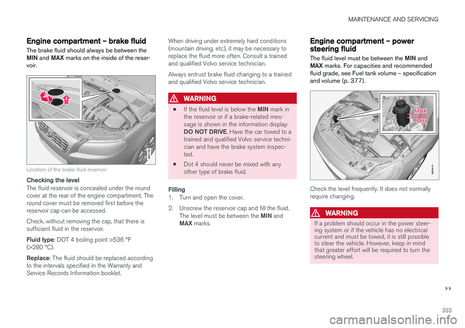
Location of the brake fluid reservoir
Checking the level
The fluid reservoir is concealed under the round cover at the rear of the engine compartment. Theround cover must be removed first before thereservoir cap can be accessed. Check, without removing the cap, that there is sufficient fluid in the reservoir. Fluid type : DOT 4 boiling point >536 °F
(>280 °C).Replace : The fluid should be replaced according
to the intervals specified in the Warranty and Service Records Information booklet. When driving under extremely hard conditions(mountain driving, etc), it may be necessary toreplace the fluid more often. Consult a trainedand qualified Volvo service technician. Always entrust brake fluid changing to a trained and qualified Volvo service technician.
WARNING
•
If the fluid level is below the
MIN mark in
the reservoir or if a brake-related mes- sage is shown in the information display: DO NOT DRIVE . Have the car towed to a
trained and qualified Volvo service techni- cian and have the brake system inspec-ted.
• Dot 4 should never be mixed with anyother type of brake fluid.
Filling
1. Turn and open the cover.
2. Unscrew the reservoir cap and fill the fluid.
The level must be between the MIN and
MAX marks.
Engine compartment – power steering fluid
The fluid level must be between the MIN and
MAX marks. For capacities and recommended
fluid grade, see Fuel tank volume – specification and volume (p. 377).
Check the level frequently. It does not normally require changing.
WARNING
If a problem should occur in the power steer- ing system or if the vehicle has no electricalcurrent and must be towed, it is still possibleto steer the vehicle. However, keep in mindthat greater effort will be required to turn thesteering wheel.
Page 356 of 396
||
MAINTENANCE AND SERVICING
* Option/accessory.
354
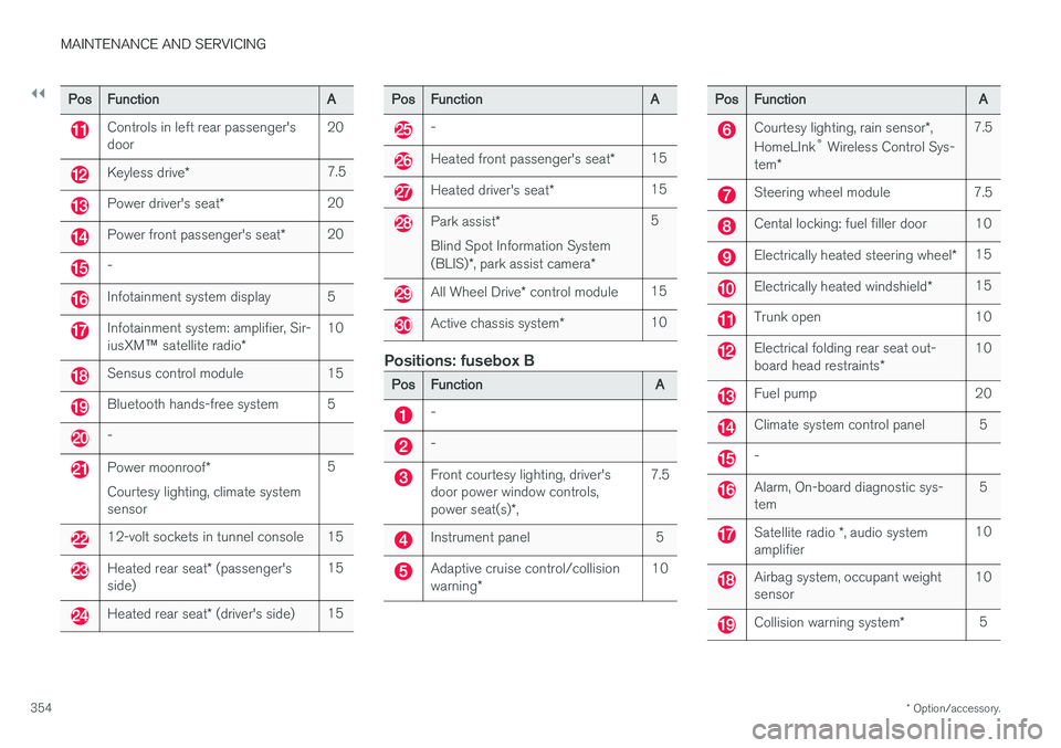
Pos Function A
Controls in left rear passenger's door20
Keyless drive
* 7.5
Power driver's seat
*20
Power front passenger's seat
*20
-
Infotainment system display 5
Infotainment system: amplifier, Sir- iusXM
™ satellite radio * 10
Sensus control module 15
Bluetooth hands-free system 5
-
Power moonroof
*
Courtesy lighting, climate system sensor 5
12-volt sockets in tunnel console 15
Heated rear seat
* (passenger's
side) 15
Heated rear seat
* (driver's side) 15
Pos
Function A
-
Heated front passenger's seat*15
Heated driver's seat
*15
Park assist
*
Blind Spot Information System (BLIS) *, park assist camera *5
All Wheel Drive
* control module 15
Active chassis system
*10
Positions: fusebox B
Pos
Function A
-
-
Front courtesy lighting, driver's door power window controls, power seat(s)*, 7.5
Instrument panel 5
Adaptive cruise control/collision warning
* 10
Pos
Function A
Courtesy lighting, rain sensor*,
HomeLInk ®
Wireless Control Sys-
tem * 7.5
Steering wheel module 7.5
Cental locking: fuel filler door 10
Electrically heated steering wheel
*15
Electrically heated windshield
*15
Trunk open 10
Electrical folding rear seat out- board head restraints
*10
Fuel pump 20
Climate system control panel 5
-
Alarm, On-board diagnostic sys- tem
5
Satellite radio
*, audio system
amplifier 10
Airbag system, occupant weight sensor
10
Collision warning system
*5
Page 381 of 396
SPECIFICATIONS
}}
379
Air conditioning – specification and volume
The air conditioning system in your vehicle con- tains the following:
Refrigerant : R134a (HFC134a)
Volume: 1.7 lbs (770 g)
Compressor oil : PAG
Battery specifications If the battery is replaced, replace it with a battery of the same cold start capacity as the original(see the decal on the battery).
General information
WARNING
PROPOSITION 65 WARNING! Battery posts, terminals, and related accesso- ries contain lead and lead compounds, chemi-cals known to the state of California to causecancer and reproductive harm. Wash handsafter handling.
12 volt system with a voltage-regulated alterna- tor. Single pole system in which the chassis andengine block are used as conductors. The nega-tive terminal is connected to the chassis.
Voltage (V) 12 Cold start capacity (Cold CrankingAmperes - CCA) (A) 760
Dimensions, L×W×H in.(mm) 10.9×6.9×7.5
(278×175×190)
Capacity (Ah) 70
Symbols – general information The following tables list the most common warn- ing and indicator lights and symbols and a refer-ence to where more detailed information can befound.
IntroductionThe symbols in the vehicle's various displays are divided into three main categories: • Warning symbols
• Indicator symbols
• Information symbols
The following tables list the most common sym- bols, their meaning and the pages in this manualthat provide more detailed information.
NOTE
Not all of the symbols shown in the related articles are available in all models or on allmarkets. Local variations may occur.
Warning symbol
: The red warning symbol illuminates to
indicate a problem related to safety and/or driva- bility. A message will also appear in the maininstruments panel's display.
Information symbol
: The information symbol illuminates and a
text message is displayed to provide the driver
Page 382 of 396
||
SPECIFICATIONS
380with necessary information about one of the vehi- cle's systems.
Related information
•
Information displays – indicator symbols(p. 67)
• Information displays – warning symbols(p. 69)
• Information display – messages (p. 109)
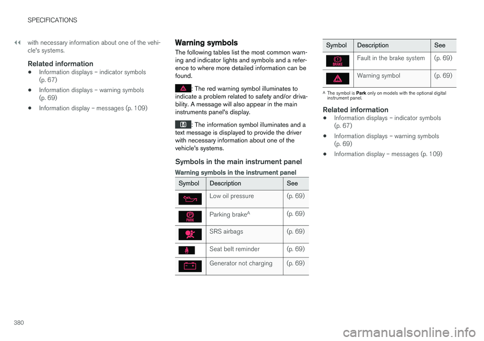
Warning symbols
The following tables list the most common warn- ing and indicator lights and symbols and a refer-ence to where more detailed information can befound.
: The red warning symbol illuminates to
indicate a problem related to safety and/or driva- bility. A message will also appear in the maininstruments panel's display.
: The information symbol illuminates and a
text message is displayed to provide the driver with necessary information about one of thevehicle's systems.
Symbols in the main instrument panel
Warning symbols in the instrument panel
Symbol Description See
Low oil pressure (p. 69)
Parking brakeA
(p. 69)
SRS airbags (p. 69)
Seat belt reminder (p. 69)
Generator not charging (p. 69)
SymbolDescription See
Fault in the brake system (p. 69)
Warning symbol (p. 69)
A
The symbol is Park only on models with the optional digital
instrument panel.
Related information
• Information displays – indicator symbols (p. 67)
• Information displays – warning symbols(p. 69)
• Information display – messages (p. 109)
Page 383 of 396
SPECIFICATIONS
}}
* Option/accessory.381
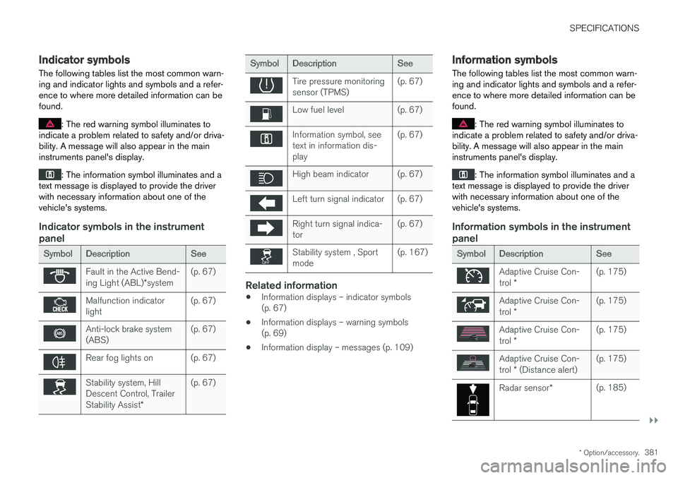
Indicator symbols
The following tables list the most common warn- ing and indicator lights and symbols and a refer-ence to where more detailed information can befound.
: The red warning symbol illuminates to
indicate a problem related to safety and/or driva- bility. A message will also appear in the maininstruments panel's display.
: The information symbol illuminates and a
text message is displayed to provide the driver with necessary information about one of thevehicle's systems.
Indicator symbols in the instrument panel
Symbol Description See
Fault in the Active Bend- ing Light (ABL)*system (p. 67)
Malfunction indicator light
(p. 67)
Anti-lock brake system (ABS)(p. 67)
Rear fog lights on (p. 67)
Stability system, Hill Descent Control, Trailer Stability Assist
*(p. 67)
Symbol
Description See
Tire pressure monitoring sensor (TPMS)(p. 67)
Low fuel level (p. 67)
Information symbol, see text in information dis-play(p. 67)
High beam indicator (p. 67)
Left turn signal indicator (p. 67)
Right turn signal indica- tor
(p. 67)
Stability system , Sport mode(p. 167)
Related information
•
Information displays – indicator symbols (p. 67)
• Information displays – warning symbols(p. 69)
• Information display – messages (p. 109)
Information symbols
The following tables list the most common warn- ing and indicator lights and symbols and a refer-ence to where more detailed information can befound.
: The red warning symbol illuminates to
indicate a problem related to safety and/or driva- bility. A message will also appear in the maininstruments panel's display.
: The information symbol illuminates and a
text message is displayed to provide the driver with necessary information about one of thevehicle's systems.
Information symbols in the instrument panel
Symbol Description See
Adaptive Cruise Con- trol * (p. 175)
Adaptive Cruise Con- trol
* (p. 175)
Adaptive Cruise Con- trol
* (p. 175)
Adaptive Cruise Con- trol
* (Distance alert) (p. 175)
Radar sensor
*(p. 185)
Page 384 of 396
||
SPECIFICATIONS
* Option/accessory.
382
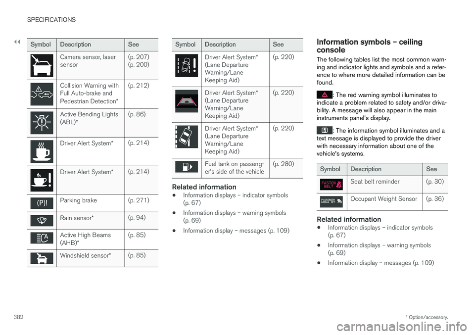
Symbol Description See
Camera sensor, laser sensor(p. 207)(p. 200)
Collision Warning with Full Auto-brake and Pedestrian Detection
*(p. 212)
Active Bending Lights (ABL)
* (p. 86)
Driver Alert System
*(p. 214)
Driver Alert System
*(p. 214)
Parking brake (p. 271)
Rain sensor
* (p. 94)
Active High Beams (AHB)
* (p. 85)
Windshield sensor
*(p. 85)
Symbol
Description See
Driver Alert System*
(Lane Departure Warning/LaneKeeping Aid) (p. 220)
Driver Alert System
*
(Lane Departure Warning/LaneKeeping Aid) (p. 220)
Driver Alert System
*
(Lane Departure Warning/LaneKeeping Aid) (p. 220)
Fuel tank on passeng- er's side of the vehicle
(p. 280)
Related information
•
Information displays – indicator symbols (p. 67)
• Information displays – warning symbols(p. 69)
• Information display – messages (p. 109)
Information symbols – ceiling console
The following tables list the most common warn- ing and indicator lights and symbols and a refer-ence to where more detailed information can befound.
: The red warning symbol illuminates to
indicate a problem related to safety and/or driva- bility. A message will also appear in the maininstruments panel's display.
: The information symbol illuminates and a
text message is displayed to provide the driver with necessary information about one of thevehicle's systems.
Symbol Description See
Seat belt reminder (p. 30)
Occupant Weight Sensor (p. 36)
Related information
•Information displays – indicator symbols (p. 67)
• Information displays – warning symbols(p. 69)
• Information display – messages (p. 109)
Page 385 of 396
SPECIFICATIONS
* Option/accessory.383
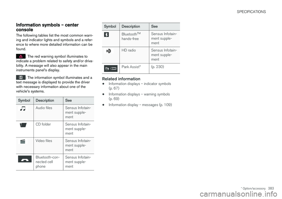
Information symbols – center console
The following tables list the most common warn- ing and indicator lights and symbols and a refer-ence to where more detailed information can befound.
: The red warning symbol illuminates to
indicate a problem related to safety and/or driva- bility. A message will also appear in the maininstruments panel's display.
: The information symbol illuminates and a
text message is displayed to provide the driver with necessary information about one of thevehicle's systems.
Symbol Description See
Audio files Sensus Infotain-
ment supple- ment
CD folder Sensus Infotain-ment supple- ment
Video files Sensus Infotain-ment supple- ment
Bluetooth-con- nected cellphoneSensus Infotain-ment supple-ment
Symbol
Description See
BluetoothTM
hands-free Sensus Infotain- ment supple-ment
HD radio Sensus Infotain-
ment supple- ment
Park Assist*(p. 230)
Related information
•Information displays – indicator symbols (p. 67)
• Information displays – warning symbols(p. 69)
• Information display – messages (p. 109)