steering wheel VOLVO S60 2018 Owner´s Manual
[x] Cancel search | Manufacturer: VOLVO, Model Year: 2018, Model line: S60, Model: VOLVO S60 2018Pages: 396, PDF Size: 9.4 MB
Page 285 of 396
STARTING AND DRIVING
}}
283
Some of the above mentioned items and others are checked at the standard maintenance inter-vals.
WARNING
Driving with the trunk open:
Driving with the
trunk open could lead to poisonous exhaust gases entering the passenger compartment. Ifthe trunk must be kept open for any reason,proceed as follows:
• Close the windows
• Set the ventilation system control to air flow to floor, windshield and side windowsand the blower control to its highest set-ting.
Handling and roadholdingAt the specified curb weight your vehicle has atendency to understeer, which means that thesteering wheel has to be turned more than mightseem appropriate for the curvature of a bend.This ensures good stability and reduces the riskof rear wheel skid. Remember that these proper-ties can alter with the vehicle load. The heavierthe load in the trunk, the less the tendency toundersteer. • Vehicle load, tire design and inflation pres- sure all affect vehicle handling. Therefore,check that the tires are inflated to the rec-ommended pressure according to the vehicleload. Loads should be distributed so that capacity weight or maximum permissible axleloads are not exceeded.
• At the specified curb weight your vehicle hasa tendency to understeer, which means thatthe steering wheel has to be turned morethan might seem appropriate for the curva-ture of a bend. This ensures good stabilityand reduces the risk of rear wheel skid.Remember that these properties can alterwith the vehicle load. The heavier the load inthe trunk, the less the tendency to under-steer.
Related information
•Climate – general information (p. 120)
Towing a trailer When towing a trailer, always observe the legal requirements of the state/province.
NOTE
For the maximum trailer and tongue weights recommended by Volvo, see Weights (p. 371)
•
All Volvo models are equipped with energy- absorbing shock-mounted bumpers. Trailerhitch installation should not interfere with theproper operation of this bumper system.
Trailer towing does not normally present any par-ticular problems, but take into consideration:
• Increase tire pressure to recommended fullpressure, see the tire inflation decal on thedriver's door opening.
• When your vehicle is new, avoid towing heavytrailers during the first 620 miles (1,000 km).
• Maximum speed when towing a trailer:50 mph (80 km/h).
• Engine and transmission are subject toincreased loads. Therefore, engine coolanttemperature should be closely watched whendriving in hot climates or hilly terrain. Use alower gear and turn off the air conditioner ifthe temperature gauge needle enters the redrange.
Page 287 of 396
STARTING AND DRIVING
285
WARNING
•Bumper-attached trailer hitches must not be used on Volvos, nor should safetychains be attached to the bumper.
• Trailer hitches attaching to the vehiclerear axle must not be used.
• Never connect a trailer's hydraulic brakesystem directly to the vehicle brake sys-tem, nor a trailer's lighting system directlyto the vehicle lighting system. Consultyour nearest authorized Volvo retailer forcorrect installation.
• When towing a trailer, the trailer's safetychains or wire must be correctly fastenedto the attachment points provided in thetrailer hitch on the vehicle. The safetychain or wire must never be fastened toor wound around the towing ball.
Trailer cable
An adapter is required if the vehicle's trailer hitch has a 13-pin connector and the trailer has 7 pins.Use an adapter cable approved by Volvo. Makesure the cable does not drag on the ground.
Related information
•
Loading – general (p. 138)
Trailer Stability Assist (TSA)
Trailer Stability Assist is a system designed to help stabilize a vehicle that is towing a trailerwhen the vehicle and trailer have begun to swayand is part of the stability system. For informationon the stability system, see Stability system –introduction (p. 166)
FunctionA vehicle towing a trailer may begin to sway for various reasons. Normally this only occurs at highspeeds but, for example, if the trailer is overloa-ded or if the load is unevenly distributed in thetrailer, there is risk of swaying at speeds betweenapproximately 45-55 mph (70-90 km/h). Swaying may be caused by factors such as:
• The vehicle and trailer are hit by a sudden, strong crosswind
• The vehicle and trailer are traveling on anuneven road surface or drive over a bump
• Sudden movements of the steering wheel
Facts about TSA
• TSA intervenes at speeds above approxi-mately 40 mph (60 km/h)
• The stability system symbol in the instrumentpanel will flash when TSA is working
• If the driver switches off the stability system'sSpin Control function, TSA will also beswitched off (but will be on again the nexttime the engine is started) •
TSA may not intervene when the vehicle andtrailer begin to sway if the driver tries to com-pensate for the swaying motion by movingthe steering wheel rapidly
How TSA worksOnce swaying has begun, it can be very difficultto stop, which makes it difficult to control thevehicle and trailer. The TSA system continuously monitors the vehi- cle's movements, particularly lateral movement. Ifthe system detects a tendency to sway, thebrakes are applied individually on the frontwheels, which has a stabilizing effect on the vehi-cle and trailer. This is often enough to enable thedriver to regain control of the vehicle. If this is not adequate to stop the swaying motion, the brakes are applied to all of the wheels on thevehicle and on the trailer if it is equipped withbrakes, and engine power is temporarily reduced.As the swaying motion begins to decrease andthe vehicle-trailer have once again become sta-ble, TSA will now stop regulating the brakes/engine power and the driver regains control ofthe vehicle.
Related information
•
Towing a trailer (p. 283)
• Loading – general (p. 138)
Page 289 of 396
STARTING AND DRIVING
}}
287
Attaching the towing eyeletThe towing eyelet is located under the floor of the trunk. This eyelet must be screwedinto the positions provided on the right sidesof either the front or rear bumper (see illus-tration).
There are two different types of covers over the openings for the towing eyelet and theyhave to be opened differently.
• If the cover has a notch, insert a coin, etc.,into the notch and pry open the edge ofthe cover. Open the cover completely andremove it.
• If the cover has a mark along one edge orin a corner, press the mark while pryingout the opposite side/corner using a coin,etc. Open the cover and remove it.
Screw the towing eyelet in place, first by handand then using the tire iron until it is securely inplace. After the vehicle has been towed, the eyelet should be removed and returned to its storagelocation. Press the cover for the attachment point back into position.
WARNING
• When the vehicle is being towed, the igni- tion should be in mode
II (in mode I, all of
the vehicle's airbags are deactivated). For more information, see Ignition modes(p. 74)
• Never remove the remote key from theignition slot when the vehicle is beingtowed. For vehicles with keyless drive, theremote key must remain inside the vehi-cle.
• The power brakes and power steering willnot function when the engine is not run-ning. Approximately 5 times more pres-sure will be required on the brake pedaland the steering wheel will be considera-bly harder to turn.
• The towing eyelets must not be used forpulling the vehicle out of a ditch or forany similar purpose involving severestrain.
Related information
•Towing the vehicle (p. 286)
• Towing by tow truck (p. 287)
Towing by tow truck
When necessary, call for professional help from an authorized towing company. Volvo recom-mends the use of flat bed equipment.
CAUTION
In certain conditions, the towing eyelet may be used to pull the vehicle onto aflatbed tow truck.
• The vehicle's position and ground clear-ance determine if it can be pulled up ontoa flatbed tow truck using the towing eye-let.
• If the angle of the tow truck
Page 319 of 396
WHEELS AND TIRES
}}
* Option/accessory.317
Tire sealing system * – sealing a
hole The tire sealing system can be used to tempo- rarily seal a hole in the tread surface of a tire.
Stage 1: Sealing the hole1. Peel off the speed limit sticker and affix it to the steering wheel hub where it will be clearly visible to the driver.
2. Ensure that the on/off switch is in position 0
(the 0 side of the switch should be pressed
down).
WARNING
Contact with the sealing compound may cause skin irritation. If contact occurs, washthe affected area immediately with soap andwater.
3. Unscrew the orange cover over the bottle holder on the compressor and unscrew the cap on the bottle of sealing compound.
NOTE
Do not break the seal on the bottle. This occurs automatically when the bottle isscrewed into the holder.
4. Screw the bottle into the bottle holder as faras possible.
WARNING
The bottle is equipped with a catch to keep it securely in place and help prevent sealingcompound leakage. Once in place, the bottlecannot be unscrewed. This must be done by atrained and qualified Volvo service technician.
5. Remove the valve cap from the tire
Page 321 of 396
WHEELS AND TIRES
}}
* Option/accessory.319
WARNING
If heavy vibrations, unsteady steering behavior, or noises should occur while driving, reducespeed and park the vehicle in a safe place.Recheck the tire for bumps, cracks, or othervisible damage, and recheck its inflation pres-sure. If the pressure is below 19 psi (1.3 bar),do not continue driving. Have the vehicletowed to a trained and qualified Volvo servicetechnician.
Tire sealing system – checking inflation pressure The tire sealing system can also be used to check the tires' inflation pressure.
Stage 2: Checking inflation pressure1. Reconnect the tire sealing system's hose to
the tire's inflation valve as described in stage
1 , see Tire sealing system * – sealing a hole
(p. 317).
2. Refer to the inflation pressure table in this chapter for the correct inflation pressure. If the tire needs to be inflated, start the tiresealing system
Page 333 of 396
MAINTENANCE AND SERVICING
* Option/accessory.331
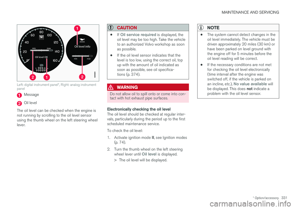
Left: digital instrument panel *, Right: analog instrument
panel
Message
Oil level
The oil level can be checked when the engine is not running by scrolling to the oil level sensorusing the thumb wheel on the left steering wheellever.
CAUTION
• If Oil service required is displayed, the
oil level may be too high. Take the vehicle to an authorized Volvo workshop as soonas possible.
• If the oil level sensor indicates that thelevel is too low, using the correct oil, topup with the amount of oil indicated assoon as possible, see oil specifica-tions (p. 374).
WARNING
Do not allow oil to spill onto or come into con- tact with hot exhaust pipe surfaces.
Electronically checking the oil level
The oil level should be checked at regular inter- vals, particularly during the period up to the firstscheduled maintenance service. To check the oil level:1.
Activate ignition mode II, see Ignition modes
(p. 74).
2. Turn the thumb wheel on the left steering wheel lever until
Oil level is displayed.
> The oil level will be displayed.
NOTE
• The system cannot detect changes in the oil level immediately. The vehicle must bedriven approximately 20 miles (30 km) orhave been parked on level ground withthe engine off for 5 minutes before theoil level reading will be correct.
• If the necessary conditions are not metfor checking the oil level electronically(time interval after the engine wasswitched off, if the vehicle is parked on an incline, etc.),
No value available will
be displayed. This does not indicate a
problem with the oil level sensor.
Page 335 of 396
MAINTENANCE AND SERVICING
}}
333
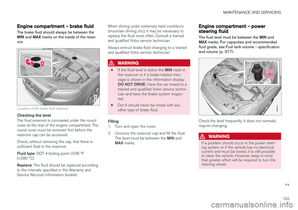
Engine compartment – brake fluid
The brake fluid should always be between the MIN and MAX marks on the inside of the reser-
voir.
Location of the brake fluid reservoir
Checking the level
The fluid reservoir is concealed under the round cover at the rear of the engine compartment. Theround cover must be removed first before thereservoir cap can be accessed. Check, without removing the cap, that there is sufficient fluid in the reservoir. Fluid type : DOT 4 boiling point >536 °F
(>280 °C).Replace : The fluid should be replaced according
to the intervals specified in the Warranty and Service Records Information booklet. When driving under extremely hard conditions(mountain driving, etc), it may be necessary toreplace the fluid more often. Consult a trainedand qualified Volvo service technician. Always entrust brake fluid changing to a trained and qualified Volvo service technician.
WARNING
•
If the fluid level is below the
MIN mark in
the reservoir or if a brake-related mes- sage is shown in the information display: DO NOT DRIVE . Have the car towed to a
trained and qualified Volvo service techni- cian and have the brake system inspec-ted.
• Dot 4 should never be mixed with anyother type of brake fluid.
Filling
1. Turn and open the cover.
2. Unscrew the reservoir cap and fill the fluid.
The level must be between the MIN and
MAX marks.
Engine compartment – power steering fluid
The fluid level must be between the MIN and
MAX marks. For capacities and recommended
fluid grade, see Fuel tank volume – specification and volume (p. 377).
Check the level frequently. It does not normally require changing.
WARNING
If a problem should occur in the power steer- ing system or if the vehicle has no electricalcurrent and must be towed, it is still possibleto steer the vehicle. However, keep in mindthat greater effort will be required to turn thesteering wheel.
Page 356 of 396
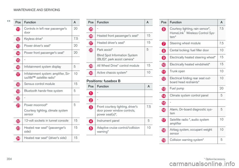
||
MAINTENANCE AND SERVICING
* Option/accessory.
354
Pos Function A
Controls in left rear passenger's door20
Keyless drive
* 7.5
Power driver's seat
*20
Power front passenger's seat
*20
-
Infotainment system display 5
Infotainment system: amplifier, Sir- iusXM
™ satellite radio * 10
Sensus control module 15
Bluetooth hands-free system 5
-
Power moonroof
*
Courtesy lighting, climate system sensor 5
12-volt sockets in tunnel console 15
Heated rear seat
* (passenger's
side) 15
Heated rear seat
* (driver's side) 15
Pos
Function A
-
Heated front passenger's seat*15
Heated driver's seat
*15
Park assist
*
Blind Spot Information System (BLIS) *, park assist camera *5
All Wheel Drive
* control module 15
Active chassis system
*10
Positions: fusebox B
Pos
Function A
-
-
Front courtesy lighting, driver's door power window controls, power seat(s)*, 7.5
Instrument panel 5
Adaptive cruise control/collision warning
* 10
Pos
Function A
Courtesy lighting, rain sensor*,
HomeLInk ®
Wireless Control Sys-
tem * 7.5
Steering wheel module 7.5
Cental locking: fuel filler door 10
Electrically heated steering wheel
*15
Electrically heated windshield
*15
Trunk open 10
Electrical folding rear seat out- board head restraints
*10
Fuel pump 20
Climate system control panel 5
-
Alarm, On-board diagnostic sys- tem
5
Satellite radio
*, audio system
amplifier 10
Airbag system, occupant weight sensor
10
Collision warning system
*5
Page 364 of 396
||
MAINTENANCE AND SERVICING
362
Leather care
Volvo's leather upholstery is manufactured with a protectant to repel soiling. Over time, sunlight,grease and dirt can break down the protection.Staining, cracking, scuffing, and fading can result. Volvo offers an easy-to-use, non-greasy leather care kit formulated to clean and beautify yourvehicle's leather, and to renew the protectivequalities of its finish. The cleaner removes dirtand oil buildup. The light cream protectantrestores a barrier against soil and sunlight. Volvo also offers a special leather softener that should be applied after the cleaner and protec-tant. It leaves leather soft and smooth, andreduces friction between leather and other fin-ishes in the vehicle. Volvo recommends cleaning, protecting and con- ditioning your vehicle's leather two to four times ayear. Ask your Volvo retailer about Leather CareKit 951 0251 and Leather Softener 943 7429.
Cleaning leather upholstery
1. Pour leather cleaner on a damp sponge andsqueeze it until the cleaner foams.
2. Apply the foam to the stain by moving the sponge with circular movements.
3. Dampen the stain thoroughly with the sponge. Let the sponge absorb the stain, do not rub.
4. Dry the stain with soft paper towels or a towel, and allow the leather to dry completely.
Protecting leather upholstery
1. Put a small amount of protectant cream on acloth and apply a thin coating of cream to the upholstery with light circular movements.
2. Allow the leather to dry for 20 minutes. This will help the leather resist staining and pro- tect against sunlight's harmful UV rays.
CAUTION
• Under no circumstances should gasoline, naphtha or similar cleaning agents beused on the plastic or the leather sincethese can cause damage.
• Take extra care when removing stainssuch as ink or lipstick since the coloringcan spread.
• Use solvents sparingly. Too much solventcan damage the seat padding.
• Start from the outside of the stain andwork toward the center.
• Sharp objects (e.g. pencils or pens in apocket) or Velcro fasteners on clothingmay damage the textile upholstery.
• Clothing that is not colorfast, such asnew jeans or suede garments, may stainthe upholstery.
Cleaning a leather-covered steering wheel
• Remove soil, dust, etc., with a damp sponge and a neutral soap solution.
• Leather should be allowed to breath. Nevercover the steering wheel with a plastic pro-tector.
• Volvo recommends cleaning, protecting andconditioning the steering wheel with Volvo'sLeather Care Kit 951 0251 and LeatherSoftener 943 7429.
If there are stains on the steering wheel: Type 1 (ink, wine, coffee, milk, sweat or blood)
–Use a soft cloth or sponge. Wipe the wheel with a solution with 5% ammonia. For bloodstains, mix approx. 1 cup (2 dl) of water andone ounce (25g) of salt and wipe the stain.
Type 2 (fat, oil, sauces, or chocolate)
1. Same procedure as for type I stains.
2. Finish by rubbing the wheel with absorbent paper or a towel.
Type 3 (dry soil or dust)
1. Remove the soil/dust with a soft brush.
2. Same procedure as for type I stains.
CAUTION
Sharp objects, such as rings, could damage the leather on the steering wheel.
Page 392 of 396

INDEX
390key blade 144, 145, 146, 148, 149, 150
, 151
locking the vehicle 147
replacing the battery 152
unlocking the vehicle 147
Reporting safety defects 27
Roadside Assistance 23
Road sign information (RSI) 170
Roof loads 139
S
Safety, occupant 26
Safety defects, reporting 27
Safety mode 44Seat belt reminder 30
Seat belts Automatic locking retractor/Emergency
locking retractor 47
buckling 29
maintenance 29
pretensioners 28
reminder 30
reminder warning light 69
securing child restraint systems 49, 52, 54
unbuckling 29
use during pregnancy 31
using 28
Seats, front 75, 76
Sensus 107Service connected service booking 325
Shiftlock 13 override 259
Side door mirrors 97, 98
Side impact airbags 39
Sign information (RSI) 170
Snow chains 305
Snow tires 305, 306
Spare tire 296
Spin control 166, 167SRS 31
Stability system 166, 167, 168 Corner Traction Control (CTC) 166
Engine Drag Control (EDC) 166
indicator light 68
Start/Stop (engine function) 260, 261, 262, 263, 264
Starting the engine 250 remote start 252
with keyless drive 250Starting the vehicleafter a crash (crash mode) 44, 45
Start inhibitor (immobilizer) 146 Steering wheel adjusting 82
heated 83
horn 82
keypad 82
Steering wheel paddles 82
Stone chips, touching up 363
Storage spaces 134
Studded tires 305, 306
Sunroof (moonroof) 101, 102
Sun shade 96, 97
Supplemental restraint system 31 warning light 69
Symbols, overview 379
T
Tailgate wiper/washer 95
Taillights, changing bulbs 339 Temperature sensor ambient 72
Temporary spare tire 296