engine VOLVO S60 CROSS COUNTRY 2017 Owner´s Manual
[x] Cancel search | Manufacturer: VOLVO, Model Year: 2017, Model line: S60 CROSS COUNTRY, Model: VOLVO S60 CROSS COUNTRY 2017Pages: 398, PDF Size: 9.47 MB
Page 288 of 398
||
STARTING AND DRIVING
286•
If the automatic transmission begins to over- heat, a message will be displayed in the textwindow.
• Avoid overload and other abusive operation.
• Hauling a trailer affects handling, durability,and economy.
• It is necessary to balance trailer brakes withthe towing vehicle brakes to provide a safestop (check and observe state/local regula-tions).
• Do not connect the trailer's brake systemdirectly to the vehicle's brake system.
• More frequent vehicle maintenance isrequired.
• Remove the ball holder when the hitch is notbeing used.
NOTE
• When parking the vehicle with a trailer on a hill, apply the parking brake before put- ting the gear selector in
P. Always follow
the trailer manufacturer's recommenda- tions for wheel chocking.
• When starting on a hill, put the gear selector in
D before releasing the parking
brake.
• If you use the manual (Geartronic) shift positions while towing a trailer, make surethe gear you select does not put toomuch strain on the engine (using toohigh a gear).
• The drawbar assembly/trailer hitch maybe rated for trailers heavier than the vehi-cle is designed to tow. Please adhere toVolvo's recommended trailer weights.
• Avoid driving with a trailer on inclines ofmore than 15%.
CAUTION
The maximum trailer weights listed are only applicable for altitudes up to 3,280 ft(1000 m) above sea level. With increasingaltitude the engine power and therefore thecar's climbing ability are impaired because ofthe reduced air density, so the maximumtrailer weight has to be reduced accordingly.The weight of the vehicle and trailer must bereduced by 10% for every further 3,280 ft(1,000 m) (or part thereof). When towing5,000 lbs (2,250 kg) hill inclination is restric-ted to 14%.
Page 289 of 398
STARTING AND DRIVING
287
WARNING
•Bumper-attached trailer hitches must not be used on Volvos, nor should safetychains be attached to the bumper.
• Trailer hitches attaching to the vehiclerear axle must not be used.
• Never connect a trailer's hydraulic brakesystem directly to the vehicle brake sys-tem, nor a trailer's lighting system directlyto the vehicle lighting system. Consultyour nearest authorized Volvo retailer forcorrect installation.
• When towing a trailer, the trailer's safetychains or wire must be correctly fastenedto the attachment points provided in thetrailer hitch on the vehicle. The safetychain or wire must never be fastened toor wound around the towing ball.
Trailer cable
An adapter is required if the vehicle's trailer hitch has a 13-pin connector and the trailer has 7 pins.Use an adapter cable approved by Volvo. Makesure the cable does not drag on the ground.
Related information
•
Loading – general (p. 138)
Trailer Stability Assist (TSA)
Trailer Stability Assist is a system designed to help stabilize a vehicle that is towing a trailerwhen the vehicle and trailer have begun to swayand is part of the stability system. For informationon the stability system, see Stability system –introduction (p. 166)
FunctionA vehicle towing a trailer may begin to sway for various reasons. Normally this only occurs at highspeeds but, for example, if the trailer is overloa-ded or if the load is unevenly distributed in thetrailer, there is risk of swaying at speeds betweenapproximately 45-55 mph (70-90 km/h). Swaying may be caused by factors such as:
• The vehicle and trailer are hit by a sudden, strong crosswind
• The vehicle and trailer are traveling on anuneven road surface or drive over a bump
• Sudden movements of the steering wheel
Facts about TSA
• TSA intervenes at speeds above approxi-mately 40 mph (60 km/h)
• The stability system symbol in the instrumentpanel will flash when TSA is working
• If the driver switches off the stability system'sSpin Control function, TSA will also beswitched off (but will be on again the nexttime the engine is started) •
TSA may not intervene when the vehicle andtrailer begin to sway if the driver tries to com-pensate for the swaying motion by movingthe steering wheel rapidly
How TSA worksOnce swaying has begun, it can be very difficultto stop, which makes it difficult to control thevehicle and trailer. The TSA system continuously monitors the vehi- cle's movements, particularly lateral movement. Ifthe system detects a tendency to sway, thebrakes are applied individually on the frontwheels, which has a stabilizing effect on the vehi-cle and trailer. This is often enough to enable thedriver to regain control of the vehicle. If this is not adequate to stop the swaying motion, the brakes are applied to all of the wheels on thevehicle and on the trailer if it is equipped withbrakes, and engine power is temporarily reduced.As the swaying motion begins to decrease andthe vehicle-trailer have once again become sta-ble, TSA will now stop regulating the brakes/engine power and the driver regains control ofthe vehicle.
Related information
•
Towing a trailer (p. 285)
• Loading – general (p. 138)
Page 290 of 398
STARTING AND DRIVING
288
Towing the vehicle Always check with state and local authorities before attempting to tow another vehiclebecause this type of towing is subject to regula-tions regarding maximum towing speed, lengthand type of towing device, lighting, etc.
1. With the remote key fully pressed into theignition slot 14
, press START/STOP ENGINE
for approximately 2 seconds to activate igni- tion mode II.
2. The remote key must remain in the ignition slot15
for the entire time that the vehicle is
being towed.
3. Keep the tow rope taut when the towing vehicle slows down by applying light pressure on the brake pedal. This will help prevent jar-ring movements of the vehicle being towed.
4. Be prepared to apply the brakes to stop the vehicle being towed.
CAUTION
General towing precautions:
• Please check with state and local author- ities before attempting this type of tow-ing, as vehicles being towed are subjectto regulations regarding maximum towingspeed, length and type of towing device,lighting, etc.
• If the vehicle's battery is dead, see Jumpstarting (p. 255) to provide current forreleasing the electric parking brake and to move the gear selector from the
P
position to N. If this is not possible, see
Transmission – shiftlock override (p. 261) for information about manually overridingthe shiftlock system to move the gear selector from P to N.
• Maximum speed: 50 mph (80 km/h). Do not exceed the maximum allowable tow-ing speed.
• Maximum distance with front wheels onground: 50 miles (80 km).
• The vehicle should only be towed in theforward direction.
Related information
• Towing eyelet (p. 288)
• Remote key – functions (p. 147)
Towing eyelet
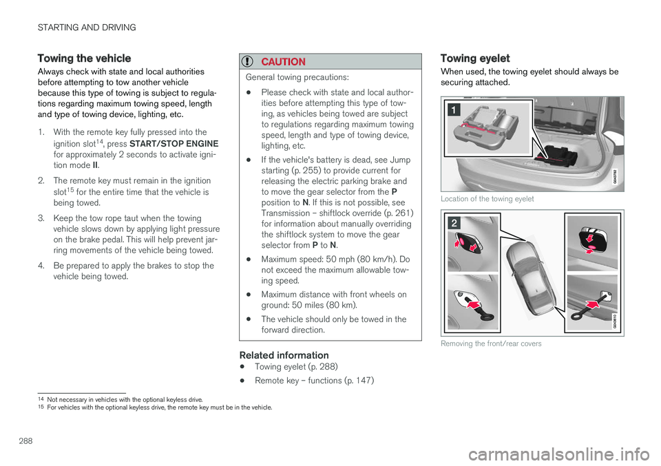
When used, the towing eyelet should always be securing attached.
Location of the towing eyelet
Removing the front/rear covers
14 Not necessary in vehicles with the optional keyless drive.
15 For vehicles with the optional keyless drive, the remote key must be in the vehicle.
Page 291 of 398
STARTING AND DRIVING
}}
289
Attaching the towing eyeletThe towing eyelet is located under the floor of the trunk. This eyelet must be screwedinto the positions provided on the right sidesof either the front or rear bumper (see illus-tration).
There are two different types of covers over the openings for the towing eyelet and theyhave to be opened differently.
• If the cover has a notch, insert a coin, etc.,into the notch and pry open the edge ofthe cover. Open the cover completely andremove it.
• If the cover has a mark along one edge orin a corner, press the mark while pryingout the opposite side/corner using a coin,etc. Open the cover and remove it.
Screw the towing eyelet in place, first by handand then using the tire iron until it is securely inplace. After the vehicle has been towed, the eyelet should be removed and returned to its storagelocation. Press the cover for the attachment point back into position.
WARNING
• When the vehicle is being towed, the igni- tion should be in mode
II (in mode I, all of
the vehicle's airbags are deactivated). For more information, see Ignition modes(p. 74)
• Never remove the remote key from theignition slot when the vehicle is beingtowed. For vehicles with keyless drive, theremote key must remain inside the vehi-cle.
• The power brakes and power steering willnot function when the engine is not run-ning. Approximately 5 times more pres-sure will be required on the brake pedaland the steering wheel will be considera-bly harder to turn.
• The towing eyelets must not be used forpulling the vehicle out of a ditch or forany similar purpose involving severestrain.
Related information
•Towing the vehicle (p. 288)
• Towing by tow truck (p. 289)
Towing by tow truck
When necessary, call for professional help from an authorized towing company. Volvo recom-mends the use of flat bed equipment.
CAUTION
In certain conditions, the towing eyelet may be used to pull the vehicle onto aflatbed tow truck.
• The vehicle's position and ground clear-ance determine if it can be pulled up ontoa flatbed tow truck using the towing eye-let.
• If the angle of the tow truck
Page 312 of 398
||
WHEELS AND TIRES
310
NOTE
The system indicates low tire pressure but does not replace normal tire maintenance. Forinformation on correct tire pressure, pleaserefer to the tire inflation decal on the driver'sdoor opening or consult your Volvo retailer.
Related information
•Tire pressure monitoring - overview (p. 308)
• Calibrating Tire Monitor (p. 310)
Calibrating Tire Monitor In order for Tire Monitor to work correctly, tire pressure reference values must be set. Thismust be done each time wheels or tire pressuresare changed.
Calibration1. Switch off the engine.
2. Inflate the tires to the desired pressure (con-
sult tire pressure placard located on the driv- er's side B-pillar (the structural member atthe side of the vehicle) and put the ignition in mode II, see Ignition modes (p. 74).
3. Press the MY CAR button on the center
console control panel and select
Settings
Car settingsTire monitoring.
4. Press OK/MENU , select
Calibrate tire
pressure and press OK/MENU again after
all of the tires have been checked and rein- flated.
5. Drive away. > The calibration process will be completedwhile driving and will be interrupted if thevehicle is parked and the engine isswitched off. Calibration continues auto-matically when driving resumes. The sys-tem will not give any confirmation whencalibration is finished although it will stateif calibration fails. When driving with heavy loads or at sustainedhighway speeds, the tire pressure should beadjusted to the recommended inflation pressuresaccording to the tire inflation pressure placardlocated on the driver's side B-pillar (the structuralmember at the side of the vehicle, at the rear ofthe driver's door opening) or to the tire inflationpressure table in the owner's information. After adjusting inflation pressure, repeat steps 1-5 above.
NOTE
Always remember to calibrate Tire Monitor when the wheels have been changed or thetire pressure has been corrected according totire pressure placard or tire pressure table. Ifcorrect reference values have not been set,the system cannot issue low tire pressurealerts correctly.
Page 316 of 398
WHEELS AND TIRES
* Option/accessory, for more information, see Introduction.
314
Tire Pressure Monitoring System (TPMS) – recalibrating
In certain cases, it may be necessary to recali- brate TPMS to conform to Volvo's recom-mended tire inflation pressures (see the tire infla-tion decal on the driver's door opening), forexample, if higher inflation pressure is necessarywhen transporting heavy loads.
Recalibrating TPMS (Canadian models
only) *
This is done in the vehicle's menu system. To recalibrate:
1. Switch off the engine.
2. Inflate the tires to the desired pressure and
put the ignition in mode I or II (see Ignition
modes (p. 74) for additional information).
3. Press the MY CAR key in the center console
control panel and select
SettingsCar
settings
Tire pressure.
4. Press OK/MENU , select
Calibrate tire
pressure and press OK/MENU again.
5. Drive the vehicle at a speed above 20 mph (30 km/h) continuously for at least 10 minutes.
> Calibration is done automatically once ini-tiated by the driver and the system does not give any confirmation when calibrationis finished. After adjusting inflation pressure, repeat steps1-5 above.
Related information
•
Tire Pressure Monitoring System (TPMS) –general information (p. 312)
• Tire Pressure Monitoring System (TPMS) –messages (p. 315)
• Tire Pressure Monitoring System (TPMS) –activating/deactivating (p. 314)
• Tire Pressure Monitoring System (TPMS) –changing wheels (p. 313)
• My Car – introduction (p. 71)
Tire Pressure Monitoring System (TPMS) – activating/deactivating
Activating/deactivating TPMS
(Canadian models only)
1. Switch off the engine. 2. Put the ignition in mode I or II (see Ignition
modes (p. 74) for additional information).
3. Press the MY CAR key in the center console
control panel and select
SettingsCar
settings
Tire pressure
4. Select Tire monitoring and press OK/
MENU to turn the system on or off.
Related information
•Tire Pressure Monitoring System (TPMS) – general information (p. 312)
Page 327 of 398
MAINTENANCE AND SERVICING
325
Maintenance – owner maintenance
Periodic maintenance requirements and intervals are described in your vehicle's Warranty andService Records Information booklet. The following points can be carried out between the normally scheduled maintenance services.
Owner maintenance
Each time the car is refueled:
• Check the engine oil level.
• Clean the windshield, windshield wipers, headlights, and taillights.
Monthly:
• Check cold tire pressure in all tires. Inspect the tires for wear.
• Check that engine coolant and other fluidlevels are between the indicated "min" and"max" markings.
• Clean interior glass surfaces with a glasscleaner and soft paper towels.
• Wipe driver information displays with a softcloth.
• Visually inspect battery terminals for corro-sion. Corrosion may indicate a loose terminalconnector, or a battery near the end of itsuseful service life. Consult your Volvo retailerfor additional information.
As needed:
Wash the car, including the undercarriage, to reduce wear that can be caused by a buildup of dirt, and corrosion that can be caused by salt res-idues. Clean leaves and twigs from air intake vents at the base of the windshield, and from other placeswhere they may collect.
NOTE
Complete service information for qualified technicians is available online for purchase orsubscription at www.volvotechinfo.com.
Related information
•
Maintenance – opening/closing hood (p. 329)
• Engine compartment – overview (p. 330)
• Engine compartment – coolant (p. 333)
• Engine compartment – engine oil (p. 331)
• Engine compartment – power steering fluid(p. 335)
• Engine compartment – washer fluid (p. 346)
• Cleaning the interior (p. 363)
• Washing the car (p. 361)
• Tire inflation – checking pressure (p. 301)
• Tires – tread wear indicator (p. 294)
Page 329 of 398
MAINTENANCE AND SERVICING
}}
* Option/accessory, for more information, see Introduction.327
Onboard Diagnostic System OBD II is part of your vehicle's computerized engine management system. It stores diagnosticinformation about your vehicle's emission con-trols. It can light the Check Engine light (MIL) if itdetects an emission control "fault." A "fault" is acomponent or system that is not performingwithin an expected range. A fault may be perma-nent or temporary. OBD II will store a messageabout any fault.
Emission inspection readiness
How do states use OBD II for emission inspections?
Many states connect a computer directly to a vehicle's OBD II system. The inspector can thenread "faults." In some states, this type of inspec-tion has replaced the tailpipe emission test.
How can my vehicle fail OBD II emission inspection?
Your vehicle can fail OBD II emission inspection for any of the following reasons.
• If your Check Engine (MIL) light is lit, yourvehicle may fail inspection.
• If your vehicle's Check Engine light was lit,but went out without any action on your part,OBD II will still have a recorded fault. Yourvehicle may pass or fail, depending on theinspection practices in your area.
• If you had recent service that required dis-connecting the battery, OBD II diagnostic information may be incomplete and "notready" for inspection. A vehicle that is notready may fail inspection.
How can I prepare for my next OBD II
emission inspection?
• If your Check Engine (MIL) light is lit – or was lit but went out without service, have yourvehicle diagnosed and, if necessary, servicedby a qualified Volvo technician.
• If you recently had service for a lit CheckEngine light, or if you had service thatrequired disconnecting the battery, a periodof driving is necessary to bring the OBD IIsystem to "ready" for inspection. Two half-hour trips of mixed stop-and-go/highwaydriving are typically needed to allow OBD II toreach readiness. Your Volvo retailer can pro-vide you with more information on planning atrip.
• Maintain your vehicle in accordance with yourvehicle's maintenance schedule.
Booking service and repairs
Connected Service Booking (CSB) makes set- ting up a time for service, maintenance and/orrepairs directly from the vehicle quick and con-venient.
Prerequisites
• The owner (primary driver) must have a valid Volvo ID. See Volvo ID (p. 20) for additionalinformation.
• The vehicle must be connected to the Inter- net using a paired Bluetooth ®
cell phone.
See your Sensus Infotainment supplement for information on pairing a cell phone. On models equipped with Volvo On Call (VOC) *,
you can connect to the Internet using your separate VOC data plan. Refer to your sepa-rate Volvo On Call manual.
• By default, the retailer where you purchasedyour vehicle will be your preferred (primary)retailer/Volvo authorized workshop who willperform service and repairs on your vehicle.To change the preferred retailer, go to DealerLocator at volvocars.com and select aretailer, click on Service Scheduler and bookan appointment at the new preferred retailer.
• In order to be guided through the on-screen steps, the menu alternative
Display
notifications must be activated.
Page 330 of 398
||
MAINTENANCE AND SERVICING
328
CSB menu accessOnce the prerequisites have been established, all CSB-related menus can be accessed in MY CAR
by pressing OK/MENU and then selecting
Maintenance & repair.
Booking information and data from the
vehicle
If you request an appointment from your vehicle, with your consent, booking information and data about your vehicle 1
will be transmitted to your
preferred retailer.
Using the serviceOnce the prerequisites have been established, all CSB-related menus can be accessed in MY CAR
by pressing OK/MENU and then selecting
Maintenance & repair.
If the time for the next regularly scheduled serv- ice is approaching, if the vehicle requires certaintypes of repairs or if a system needs to bechecked, a message will be displayed. You willthen by guided through the steps required tobook service or repairs.
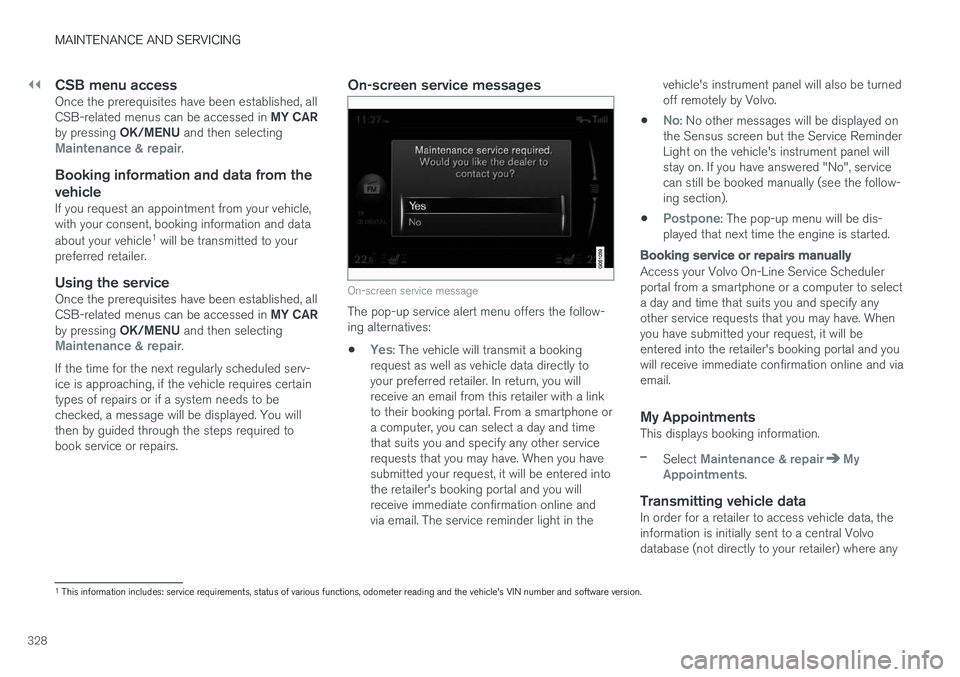
On-screen service messages
On-screen service message
The pop-up service alert menu offers the follow- ing alternatives:
•
Yes: The vehicle will transmit a booking
request as well as vehicle data directly to your preferred retailer. In return, you willreceive an email from this retailer with a linkto their booking portal. From a smartphone ora computer, you can select a day and timethat suits you and specify any other servicerequests that you may have. When you havesubmitted your request, it will be entered intothe retailer's booking portal and you willreceive immediate confirmation online andvia email. The service reminder light in the vehicle's instrument panel will also be turnedoff remotely by Volvo.
•
No: No other messages will be displayed on
the Sensus screen but the Service Reminder Light on the vehicle's instrument panel willstay on. If you have answered "No", servicecan still be booked manually (see the follow-ing section).
•
Postpone: The pop-up menu will be dis-
played that next time the engine is started.
Booking service or repairs manually
Access your Volvo On-Line Service Scheduler portal from a smartphone or a computer to selecta day and time that suits you and specify anyother service requests that you may have. Whenyou have submitted your request, it will beentered into the retailer's booking portal and youwill receive immediate confirmation online and viaemail.
My AppointmentsThis displays booking information.
–Select Maintenance & repairMy
Appointments.
Transmitting vehicle dataIn order for a retailer to access vehicle data, the information is initially sent to a central Volvodatabase (not directly to your retailer) where any
1 This information includes: service requirements, status of various functions, odometer reading and the vehicle's VIN number and software version.
Page 331 of 398
MAINTENANCE AND SERVICING
329
retailer can access or search for this information using your vehicle's VIN number. This numbercan be found in your warranty booklet or on thedashboard at the lower left corner of the wind-shield.
–Select Maintenance & repairSend
vehicle data.
Booking information and vehicle dataWhen you opt to book service from your vehicle, booking information and vehicle data will betransmitted. Vehicle data consists of a number ofparameters in the following areas:
• Service requirements
• Function status
• Fluid levels
• Odometer reading (mileage)
• Vehicle Identification Number (VIN)
• The vehicle's software version
Related information
•
Volvo ID (p. 20)
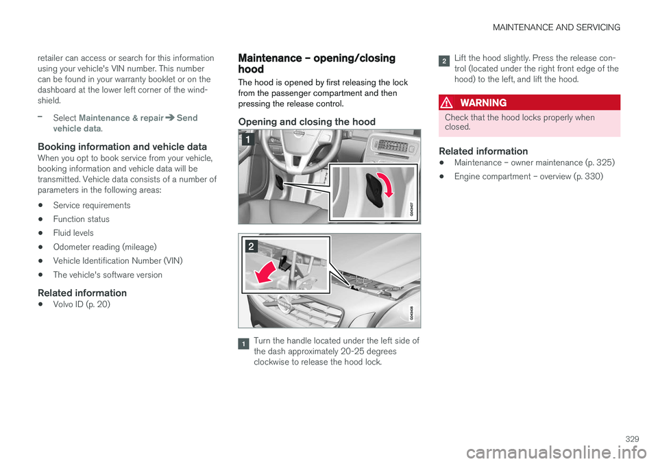
Maintenance – opening/closing hood The hood is opened by first releasing the lock from the passenger compartment and thenpressing the release control.
Opening and closing the hood
Turn the handle located under the left side of the dash approximately 20-25 degreesclockwise to release the hood lock.
Lift the hood slightly. Press the release con- trol (located under the right front edge of thehood) to the left, and lift the hood.
WARNING
Check that the hood locks properly when closed.
Related information
•Maintenance – owner maintenance (p. 325)
• Engine compartment – overview (p. 330)