engine VOLVO S60 CROSS COUNTRY 2017 Owner´s Manual
[x] Cancel search | Manufacturer: VOLVO, Model Year: 2017, Model line: S60 CROSS COUNTRY, Model: VOLVO S60 CROSS COUNTRY 2017Pages: 398, PDF Size: 9.47 MB
Page 111 of 398
INSTRUMENTS AND CONTROLS
109
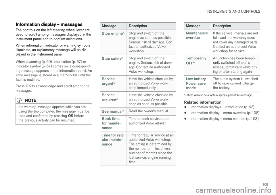
Information display – messagesThe controls on the left steering wheel lever are used to scroll among messages displayed in theinstrument panel and to confirm selections. When information, indicator or warning symbols illuminate, an explanatory message will be dis-played in the instrument panel.
When a warning (p. 69), information (p. 67) or indicator symbol (p. 67) comes on, a correspond-ing message appears in the information panel. Anerror message is stored in a memory list until thefault is rectified. Press OK to acknowledge and scroll among the
messages.
NOTE
If a warning message appears while you are using the trip computer, the message must be read and confirmed by pressing OK before
the previous activity can be resumed.
MessageDescription
Stop engineAStop and switch off the engine as soon as possible.Serious risk of damage. Con-tact an authorized Volvoworkshop.
Stop safelyAStop and switch off the engine. Serious risk of dam-age. Contact an authorizedVolvo workshop.
Service urgentAHave the vehicle checked by an authorized Volvo work-shop immediately.
Service requiredAHave the vehicle checked by an authorized Volvo work-shop as soon as possible.
See manualARead the owner's manual.
Book time for mainte-nanceTime to book service at an authorized Volvo retailer.
Time for reg- ular mainte-nanceTime for regular service at an authorized Volvo workshop.The timing is determined bythe number of miles driven,number of months since thelast service, engine runningtime.
MessageDescription
Maintenance overdueIf the service intervals are not followed, the warranty doesnot cover any damaged parts.Contact an authorized Volvoworkshop for service.
Temporarily OFFAA function has been tempo- rarily switched off and isreset automatically while driv-ing or after starting again.
Low battery Power savemodeThe audio system is switched off to save current. Chargethe battery.
A There will also be a system-specific part of this message
Related information
• Information displays – introduction (p. 63)
• Information display – menu overview (p. 108)
• Information display – menu controls (p. 108)
Page 112 of 398
INSTRUMENTS AND CONTROLS
110
Trip computer – introduction
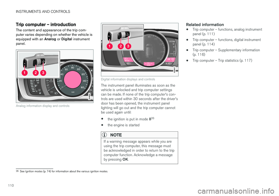
The content and appearance of the trip com- puter varies depending on whether the vehicle isequipped with an Analog or Digital instrument
panel.
Analog information display and controls
Digital information displays and controls
The instrument panel illuminates as soon as the vehicle is unlocked and trip computer settingscan be made. If none of the trip computer's con-trols are used within 30 seconds after the driver'sdoor has been opened, the instrument panellighting will go out and the trip computer cannotbe used again until: • the ignition is put in mode
II26
• the engine is started
NOTE
If a warning message appears while you are using the trip computer, this message mustbe acknowledged in order to return to the tripcomputer function. Acknowledge a message by pressing
OK.
Related information
• Trip computer – functions, analog instrument panel (p. 111)
• Trip computer – functions, digital instrumentpanel (p. 114)
• Trip computer – Supplementary information(p. 116)
• Trip computer – Trip statistics (p. 117)
26
See Ignition modes (p. 74) for information about the various ignition modes.
Page 119 of 398
INSTRUMENTS AND CONTROLS
* Option/accessory, for more information, see Introduction.117
Trip computer – Trip statistics
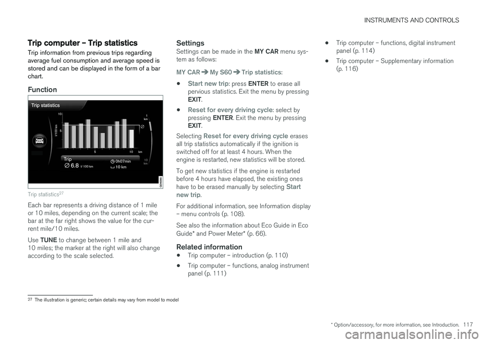
Trip information from previous trips regarding average fuel consumption and average speed isstored and can be displayed in the form of a barchart.
Function
Trip statistics 27
Each bar represents a driving distance of 1 mile or 10 miles, depending on the current scale; thebar at the far right shows the value for the cur-rent mile/10 miles. Use
TUNE to change between 1 mile and
10 miles; the marker at the right will also change according to the scale selected.
SettingsSettings can be made in the MY CAR menu sys-
tem as follows:
MY CARMy S60Trip statistics:
•
Start new trip: press ENTER to erase all
pervious statistics. Exit the menu by pressing EXIT .
•
Reset for every driving cycle: select by
pressing ENTER. Exit the menu by pressing
EXIT .
Selecting
Reset for every driving cycle erases
all trip statistics automatically if the ignition is switched off for at least 4 hours. When theengine is restarted, new statistics will be stored. To get new statistics if the engine is restarted before 4 hours have elapsed, the existing ones have to be erased manually by selecting
Start
new trip.
For additional information, see Information display – menu controls (p. 108). See also the information about Eco Guide in Eco Guide * and Power Meter * (p. 66).
Related information
• Trip computer – introduction (p. 110)
• Trip computer – functions, analog instrument panel (p. 111) •
Trip computer – functions, digital instrumentpanel (p. 114)
• Trip computer – Supplementary information(p. 116)
27
The illustration is generic; certain details may vary from model to model
Page 128 of 398
CLIMATE
* Option/accessory, for more information, see Introduction.
126
Heated seats
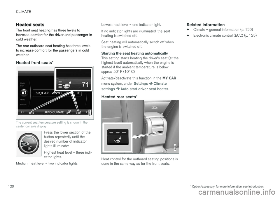
The front seat heating has three levels to increase comfort for the driver and passenger incold weather. The rear outboard seat heating has three levels to increase comfort for the passengers in coldweather.
Heated front seats *
The current seat temperature setting is shown in the center console display
Press the lower section of the button repeatedly until thedesired number of indicatorlights illuminate: Highest heat level – three indi- cator lights.
Medium heat level – two indicator lights.
Lowest heat level – one indicator light. If no indicator lights are illuminated, the seat heating is switched off. Seat heating will automatically switch off when the engine is switched off.
Starting the seat heating automatically
This setting starts heating the driver's seat (at the highest level) automatically when the engine isstarted if the ambient temperature is belowapprox. 50° F (10° C). Activate/deactivate this function in the MY CAR
menu system, under
SettingsClimate
settings
Auto start driver seat heater.
Heated rear seats *
Heat control for the outboard seating positions is done in the same way as for the front seats.
Related information
•Climate – general information (p. 120)
• Electronic climate control (ECC) (p. 125)
Page 139 of 398
LOADING AND STORAGE
* Option/accessory, for more information, see Introduction.137
Glove compartment
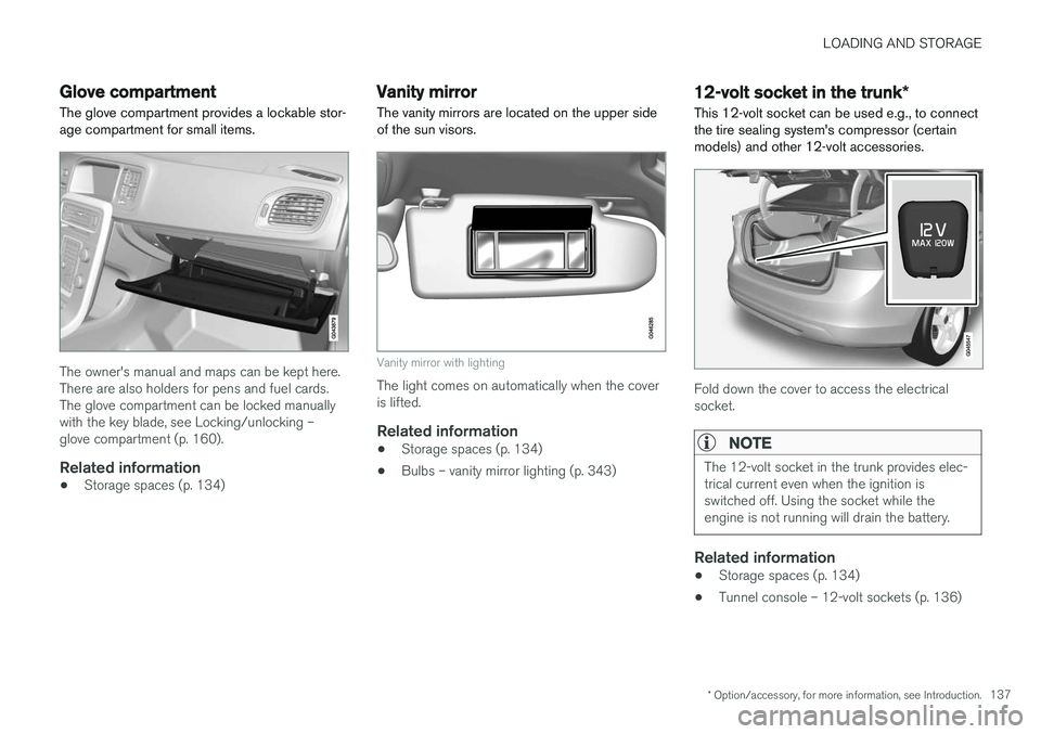
The glove compartment provides a lockable stor- age compartment for small items.
The owner's manual and maps can be kept here. There are also holders for pens and fuel cards.The glove compartment can be locked manuallywith the key blade, see Locking/unlocking –glove compartment (p. 160).
Related information
• Storage spaces (p. 134)
Vanity mirror
The vanity mirrors are located on the upper side of the sun visors.
Vanity mirror with lighting
The light comes on automatically when the cover is lifted.
Related information
• Storage spaces (p. 134)
• Bulbs – vanity mirror lighting (p. 343)
12-volt socket in the trunk
*
This 12-volt socket can be used e.g., to connect the tire sealing system's compressor (certainmodels) and other 12-volt accessories.
Fold down the cover to access the electrical socket.
NOTE
The 12-volt socket in the trunk provides elec- trical current even when the ignition isswitched off. Using the socket while theengine is not running will drain the battery.
Related information
• Storage spaces (p. 134)
• Tunnel console – 12-volt sockets (p. 136)
Page 140 of 398
LOADING AND STORAGE
138
Loading – general
The load carrying capacity of your vehicle is determined by factors such as the number ofpassengers, the amount of cargo, the weight ofany accessories that may be installed, etc.
To increase loading space, the rear seat back- rests can be folded down, see Rear seats – fold-
ing backrest (p. 81).
When loading the trunk, keep the following in
mind:
The trunk lid can be unlocked an pop-ped open slightly via the button locatedon the lighting panel, see Locking/
unlocking – trunk (p. 160).
• Load objects in the trunk against the back- rest whenever possible.
• Unstable loads can be secured to the loadanchoring eyelets with straps or web lash-ings to help keep them from shifting.
• Stop the engine and apply the parking brakewhen loading or unloading long objects. Thegear selector can be knocked out of positionby long loads, which could set the vehicle inmotion.
WARNING
• Stop the engine, put the gear selector in P
, and apply the parking brake when
loading or unloading long objects.
• The vehicle's driving characteristics may change depending on the weight and dis-tribution of the load.
• A 44-pound (20 kg) object produces aforce of 2,200 pounds (1,000 kg) in ahead-on collision at 30 mph (50 km/h).
• The rear seat should not be loaded to alevel higher than 2 in. (5 cm) below theupper edge of the rear side windows.Objects placed higher than this levelcould impede the function of the VolvoInflatable Curtain.
Related information
• Load anchoring eyelets (p. 140)
• Loading – roof load carriers (p. 139)
Ski hatch
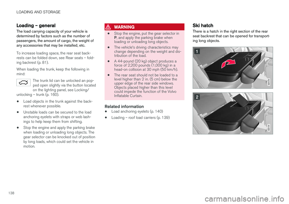
There is a hatch in the right section of the rear seat backrest that can be opened for transport-ing long objects.
Page 141 of 398
LOADING AND STORAGE
}}
139
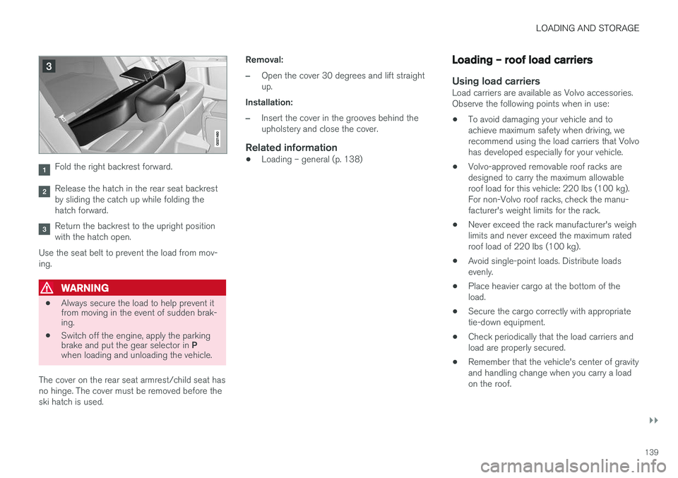
Fold the right backrest forward.
Release the hatch in the rear seat backrest by sliding the catch up while folding thehatch forward.
Return the backrest to the upright position with the hatch open.
Use the seat belt to prevent the load from mov-ing.
WARNING
• Always secure the load to help prevent it from moving in the event of sudden brak-ing.
• Switch off the engine, apply the parking brake and put the gear selector in
P
when loading and unloading the vehicle.
The cover on the rear seat armrest/child seat has no hinge. The cover must be removed before theski hatch is used. Removal:
–Open the cover 30 degrees and lift straight up.
Installation:
–Insert the cover in the grooves behind the upholstery and close the cover.
Related information
• Loading – general (p. 138)
Loading – roof load carriers
Using load carriersLoad carriers are available as Volvo accessories. Observe the following points when in use:
• To avoid damaging your vehicle and toachieve maximum safety when driving, werecommend using the load carriers that Volvohas developed especially for your vehicle.
• Volvo-approved removable roof racks aredesigned to carry the maximum allowableroof load for this vehicle: 220 lbs (100 kg).For non-Volvo roof racks, check the manu-facturer's weight limits for the rack.
• Never exceed the rack manufacturer's weighlimits and never exceed the maximum ratedroof load of 220 lbs (100 kg).
• Avoid single-point loads. Distribute loadsevenly.
• Place heavier cargo at the bottom of theload.
• Secure the cargo correctly with appropriatetie-down equipment.
• Check periodically that the load carriers andload are properly secured.
• Remember that the vehicle's center of gravityand handling change when you carry a loadon the roof.
Page 142 of 398
||
LOADING AND STORAGE
140•
The vehicle's wind resistance and fuel con- sumption will increase with the size of theload.
• Drive smoothly. Avoid rapid starts, fast cor-nering and hard braking.
Related information
• Loading – general (p. 138)
• Load anchoring eyelets (p. 140)
Load anchoring eyelets
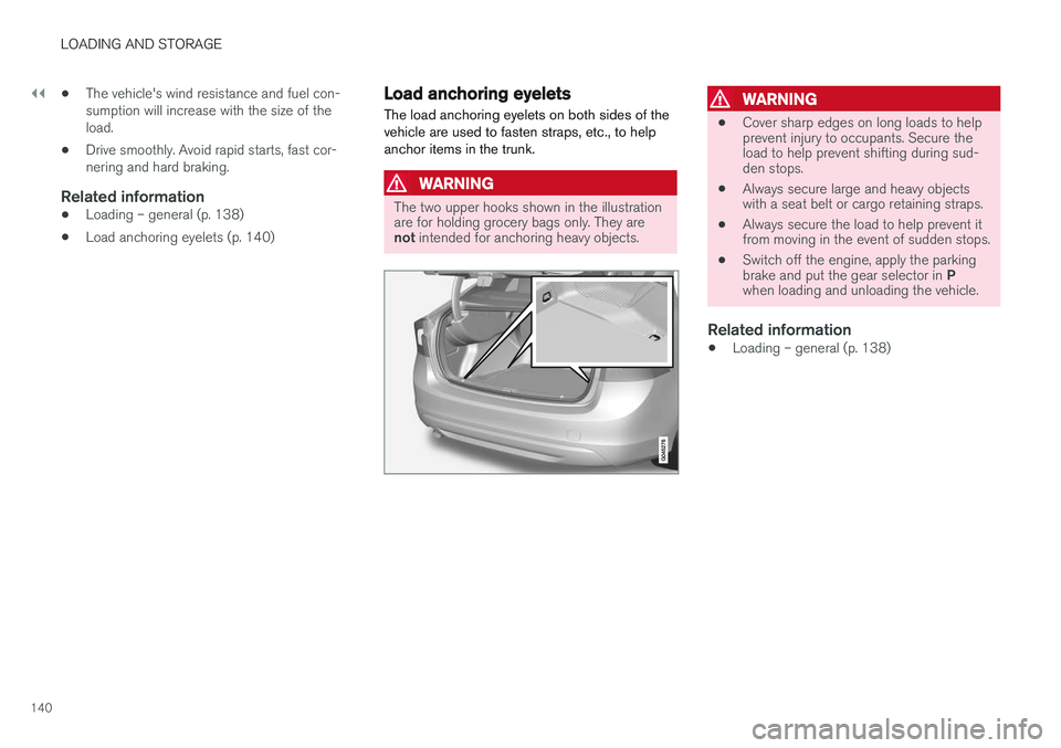
The load anchoring eyelets on both sides of the vehicle are used to fasten straps, etc., to helpanchor items in the trunk.
WARNING
The two upper hooks shown in the illustration are for holding grocery bags only. They are not intended for anchoring heavy objects.
WARNING
• Cover sharp edges on long loads to help prevent injury to occupants. Secure theload to help prevent shifting during sud-den stops.
• Always secure large and heavy objectswith a seat belt or cargo retaining straps.
• Always secure the load to help prevent itfrom moving in the event of sudden stops.
• Switch off the engine, apply the parking brake and put the gear selector in
P
when loading and unloading the vehicle.
Related information
• Loading – general (p. 138)
Page 148 of 398
LOCKS AND ALARM
* Option/accessory, for more information, see Introduction.
146
Locking/unlocking confirmation Settings can be made in the menu system for audible and visual confirmation when the vehiclehas been locked or unlocked. With these func-tions activated, the following will occur when thevehicle is locked/unlocked:
Locking confirmation
• The turn signals flash once, an audible signal sounds and the door mirrors will fold
* in.
Confirmation will only be given when all doors and the trunk are properly closed and locked.
NOTE
If you do not receive confirmation when lock- ing the vehicle, check whether a door or thetrunk is ajar, or if this feature has been turnedoff in the menu.
Unlocking confirmation
• The turn signals will flash twice and the door mirrors will fold
* out.
Making a setting
Different alternatives for locking/unlocking con- firmation can be selected in the menus by press- ing MY CAR on the center console control panel.
• To activate visual confirmation: go to
SettingsCar settingsLight settingsand select Door lock confirmation light
and/or Unlock confirmation light by
pressing OK/MENU .
• To activate audible confirmation: go to
SettingsCar settingsLock settingsand select Audible confirmation by press-
ing OK/MENU .
For a description of the menu system, see My Car – introduction (p. 71).
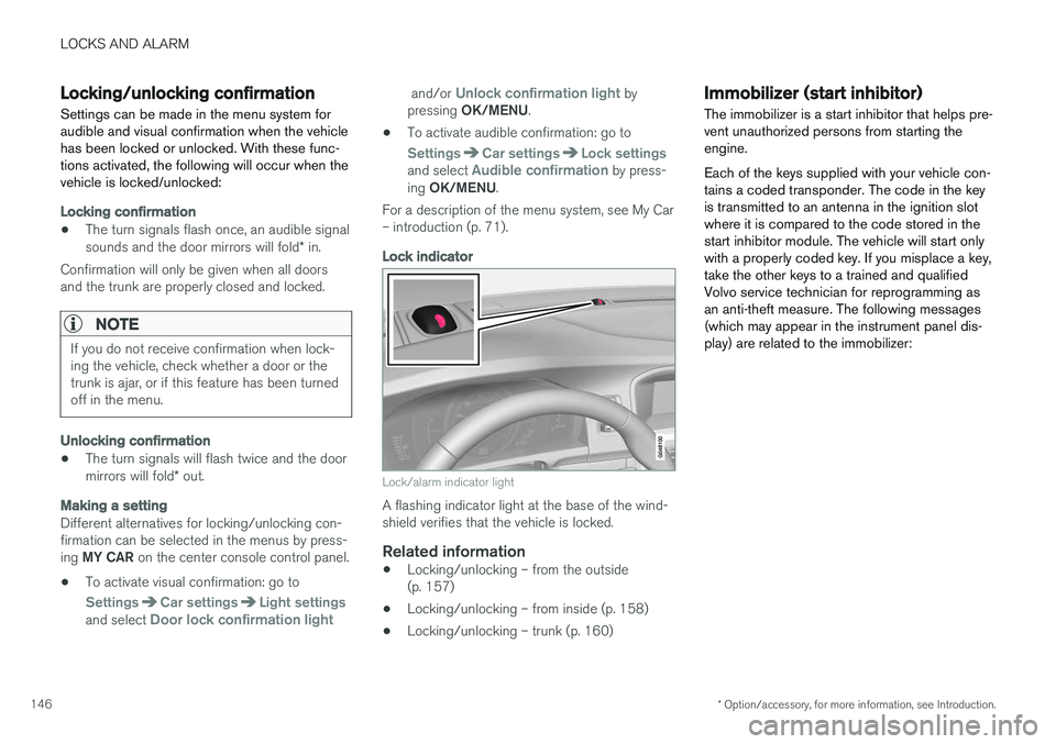
Lock indicator
Lock/alarm indicator light
A flashing indicator light at the base of the wind- shield verifies that the vehicle is locked.
Related information
• Locking/unlocking – from the outside(p. 157)
• Locking/unlocking – from inside (p. 158)
• Locking/unlocking – trunk (p. 160)
Immobilizer (start inhibitor)
The immobilizer is a start inhibitor that helps pre- vent unauthorized persons from starting theengine. Each of the keys supplied with your vehicle con- tains a coded transponder. The code in the keyis transmitted to an antenna in the ignition slotwhere it is compared to the code stored in thestart inhibitor module. The vehicle will start onlywith a properly coded key. If you misplace a key,take the other keys to a trained and qualifiedVolvo service technician for reprogramming asan anti-theft measure. The following messages(which may appear in the instrument panel dis-play) are related to the immobilizer:
Page 149 of 398
LOCKS AND ALARM
}}
* Option/accessory, for more information, see Introduction.147
MessageMeaning
Insert car keyRemote key not recognized dur- ing start. Try to start the vehicleagain.
Car key not foundVehicles with keyless drive*
only. Remote key not recog- nized during start. Try to startthe vehicle again. If the problem continues, insert the remote key into the ignitionslot and try to start the vehicleagain.
Immobil- izer Trystart againRemote key fault during start. Contact an authorized Volvoworkshop.
CAUTION
Never use force when inserting the remote key in the ignition slot. The vehicle cannot bestarted if the transponder is damaged.
USA–FCC ID: LTQWFS 125VO This device complies with part 15 of the FCC rules. Operation is subject to the following condi-tion: (1) This device may not cause harmful inter-ference, and (2) this device must accept anyinterference received, including interference thatmay cause undesired operation. Canada–IC: 3659A-WFS125VO Operation is subject to the following conditions: (1) this device may not cause interference, and(2) this device must accept any interference,including interference that may cause undesiredoperation of the device. For information on starting the vehicle, see Star- ting the engine (p. 252).
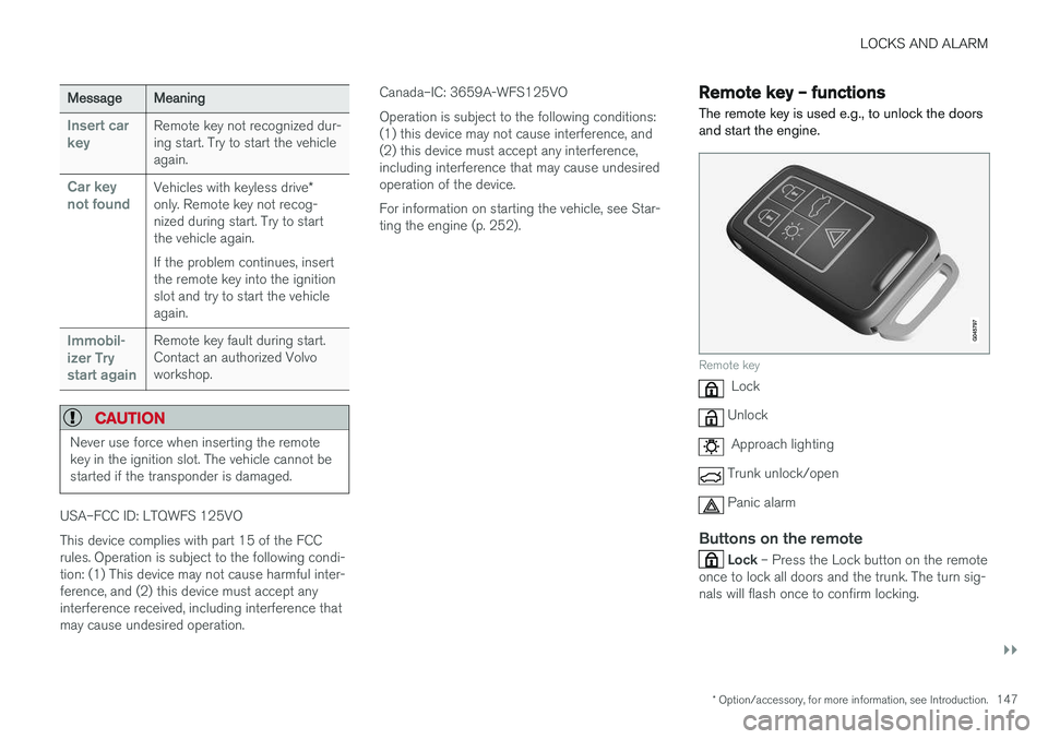
Remote key – functions
The remote key is used e.g., to unlock the doors and start the engine.
Remote key
Lock
Unlock
Approach lighting
Trunk unlock/open
Panic alarm
Buttons on the remote
Lock – Press the Lock button on the remote
once to lock all doors and the trunk. The turn sig- nals will flash once to confirm locking.