key VOLVO S60 CROSS COUNTRY 2018 Owner´s Manual
[x] Cancel search | Manufacturer: VOLVO, Model Year: 2018, Model line: S60 CROSS COUNTRY, Model: VOLVO S60 CROSS COUNTRY 2018Pages: 394, PDF Size: 9.41 MB
Page 254 of 394
STARTING AND DRIVING
* Option/accessory.
252
Switching off the engine Switch off the engine by pressing the START/
STOP ENGINE button.
If the gear selector is not in the P position or if
the vehicle is moving, press the START/STOP
ENGINE button twice or press and hold it in until
the engine switches off.
Related information
• Ignition modes (p. 74)
Engine Remote Start (ERS)
* –
introduction
ERS is a feature that makes it possible to remotely start the engine using the remote key tocool or heat the passenger compartment beforedriving.
The climate system will start using automatic set- tings. When the engine is started using ERS, it will run for a maximum of 15 minutes before automati-cally switching off again. After 2 ERS starts, theengine must be started in the normal way beforeERS can be used again.
NOTE
• Always adhere to applicable State, Prov- ince and/or Local laws regarding engineidling when using ERS.
• The service life of the remote key's bat-tery is affected by ERS use. If this featureis used frequently, the battery should bereplaced once a year, see Remote key –replacing the battery (p. 151).
WARNING
Keep the following in mind before using ERS:
• The vehicle should be in view.
• The vehicle should be unoccupied.
• The vehicle must not be parked indoors or in an enclosed area. Exhaust fumes areharmful to the health.
Related information
•
Engine Remote Start (ERS)
* – starting the
engine (p. 253)
• Engine Remote Start (ERS)
* – switching off
the engine (p. 253)
Page 255 of 394
STARTING AND DRIVING
* Option/accessory.253
Engine Remote Start (ERS) * –
starting the engine
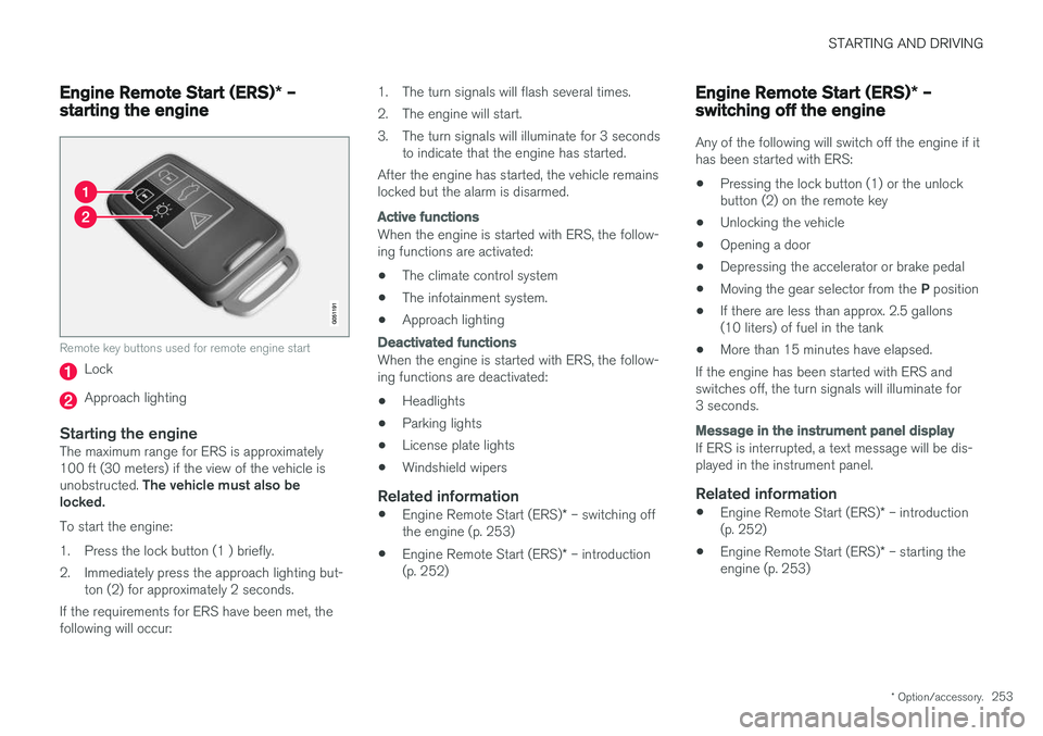
Remote key buttons used for remote engine start
Lock
Approach lighting
Starting the engineThe maximum range for ERS is approximately 100 ft (30 meters) if the view of the vehicle is unobstructed. The vehicle must also be
locked. To start the engine:
1. Press the lock button (1 ) briefly.
2. Immediately press the approach lighting but- ton (2) for approximately 2 seconds.
If the requirements for ERS have been met, the following will occur: 1. The turn signals will flash several times.
2. The engine will start.
3. The turn signals will illuminate for 3 seconds
to indicate that the engine has started.
After the engine has started, the vehicle remains locked but the alarm is disarmed.
Active functions
When the engine is started with ERS, the follow- ing functions are activated: • The climate control system
• The infotainment system.
• Approach lighting
Deactivated functions
When the engine is started with ERS, the follow- ing functions are deactivated: •
Headlights
• Parking lights
• License plate lights
• Windshield wipers
Related information
•
Engine Remote Start (ERS)
* – switching off
the engine (p. 253)
• Engine Remote Start (ERS)
* – introduction
(p. 252)
Engine Remote Start (ERS) * –
switching off the engine
Any of the following will switch off the engine if it has been started with ERS: • Pressing the lock button (1) or the unlock button (2) on the remote key
• Unlocking the vehicle
• Opening a door
• Depressing the accelerator or brake pedal
• Moving the gear selector from the
P position
• If there are less than approx. 2.5 gallons(10 liters) of fuel in the tank
• More than 15 minutes have elapsed.
If the engine has been started with ERS andswitches off, the turn signals will illuminate for3 seconds.
Message in the instrument panel display
If ERS is interrupted, a text message will be dis- played in the instrument panel.
Related information
• Engine Remote Start (ERS)
* – introduction
(p. 252)
• Engine Remote Start (ERS)
* – starting the
engine (p. 253)
Page 262 of 394
||
STARTING AND DRIVING
260
Move the gear selector from the P position.
For information on the key blade, see Detachable key blade – general information(p. 149).
Related information
• Transmission – general information (p. 255)
• Transmission – positions (p. 255)
• Transmission – Geartronic (p. 257)
• Fuel tank volume – specification and volume(p. 376)
Start/Stop – Hill Start Assist (HSA)
When starting on steep hills, HSA (see Transmis- sion – general information (p. 255)) retains pres-sure on the brake pedal for several seconds afterthe pedal has been released in order to keep thevehicle at a standstill. The brakes will be releasedafter several seconds or when the driver pressesthe accelerator pedal. The pedal will return to itsnormal position somewhat slower than normal.
Related information
•
Start/Stop – introduction (p. 260)
• Start/Stop – function (p. 261)
• Start/Stop – settings (p. 263)
• Start/Stop – Auto-stop exceptions (p. 262)
• Start/Stop – Auto-start exceptions (p. 262)
• Start/Stop – symbols and messages(p. 264)
Start/Stop – introduction
Start/Stop is a function that temporarily switches off the engine when the vehicle is not moving,for instance in heavy traffic or at a traffic light tohelp reduce fuel consumption.
Start/Stop is available with certain engines/ transmissions.
Related information
• Start/Stop – function (p. 261)
• Start/Stop – settings (p. 263)
• Start/Stop – Auto-stop exceptions (p. 262)
• Start/Stop – Auto-start exceptions (p. 262)
• Start/Stop – Hill Start Assist (HSA) (p. 260)
• Start/Stop – symbols and messages(p. 264)
Page 274 of 394
||
STARTING AND DRIVING
272
NOTE
•In an emergency the parking brake can be applied when the vehicle is moving byholding in the control. Braking will beinterrupted when the accelerator pedal isdepressed or the control is released.
• An audible signal will sound during thisprocedure if the vehicle is moving atspeeds above 6 mph (10 km/h).
Related information
•Parking brake – general information (p. 271)
• Parking brake – releasing (p. 272)
• Parking brake – symbols and messages (p. 274)
• Brakes – general (p. 267)
Parking brake – releasing
Releasing the electric parking brake
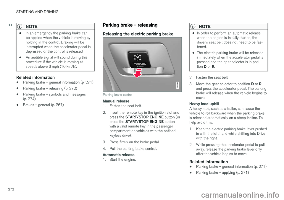
Parking brake control
Manual release
1. Fasten the seat belt.
2. Insert the remote key in the ignition slot and
press the START/STOP ENGINE button (or
press the START/STOP ENGINE button
with a valid remote key in the passenger compartment on vehicles with the optionalkeyless drive).
3. Press firmly on the brake pedal.
4. Pull the parking brake control.
Automatic release
1. Start the engine.
NOTE
• In order to perform an automatic release when the engine is initially started, thedriver
Page 288 of 394
STARTING AND DRIVING
286
Towing the vehicle Always check with state and local authorities before attempting to tow another vehiclebecause this type of towing is subject to regula-tions regarding maximum towing speed, lengthand type of towing device, lighting, etc.
1. With the remote key fully pressed into theignition slot 14
, press START/STOP ENGINE
for approximately 2 seconds to activate igni- tion mode II.
2. The remote key must remain in the ignition slot15
for the entire time that the vehicle is
being towed.
3. Keep the tow rope taut when the towing vehicle slows down by applying light pressure on the brake pedal. This will help prevent jar-ring movements of the vehicle being towed.
4. Be prepared to apply the brakes to stop the vehicle being towed.
CAUTION
General towing precautions:
• Please check with state and local author- ities before attempting this type of tow-ing, as vehicles being towed are subjectto regulations regarding maximum towingspeed, length and type of towing device,lighting, etc.
• If the vehicle's battery is dead, see Jumpstarting (p. 254) to provide current forreleasing the electric parking brake and to move the gear selector from the
P
position to N. If this is not possible, see
Transmission – shiftlock override (p. 259) for information about manually overridingthe shiftlock system to move the gear selector from P to N.
• Maximum speed: 50 mph (80 km/h). Do not exceed the maximum allowable tow-ing speed.
• Maximum distance with front wheels onground: 50 miles (80 km).
• The vehicle should only be towed in theforward direction.
Related information
• Towing eyelet (p. 286)
• Remote key – functions (p. 147)
Towing eyelet
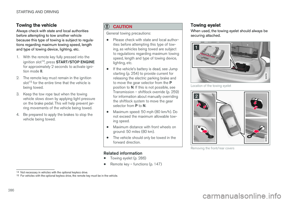
When used, the towing eyelet should always be securing attached.
Location of the towing eyelet
Removing the front/rear covers
14 Not necessary in vehicles with the optional keyless drive.
15 For vehicles with the optional keyless drive, the remote key must be in the vehicle.
Page 289 of 394
STARTING AND DRIVING
}}
287
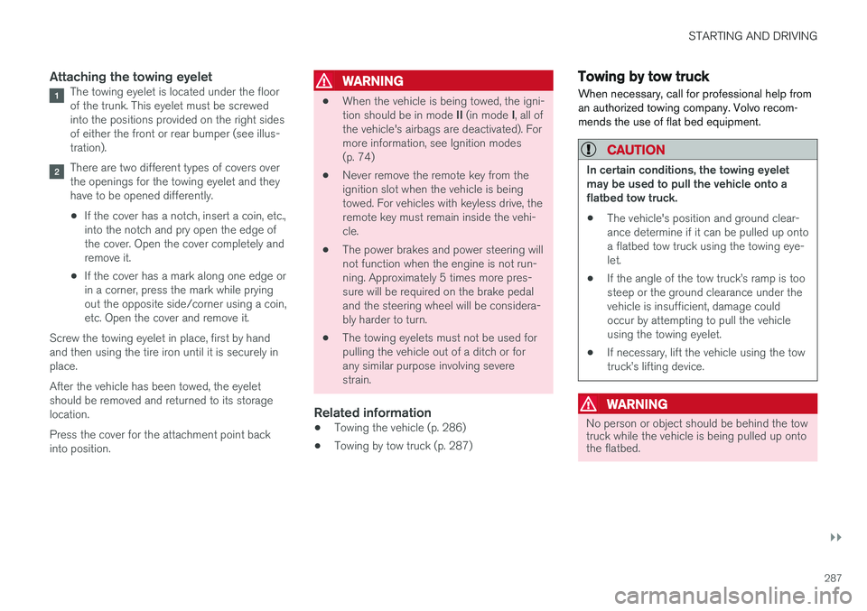
Attaching the towing eyeletThe towing eyelet is located under the floor of the trunk. This eyelet must be screwedinto the positions provided on the right sidesof either the front or rear bumper (see illus-tration).
There are two different types of covers over the openings for the towing eyelet and theyhave to be opened differently.
• If the cover has a notch, insert a coin, etc.,into the notch and pry open the edge ofthe cover. Open the cover completely andremove it.
• If the cover has a mark along one edge orin a corner, press the mark while pryingout the opposite side/corner using a coin,etc. Open the cover and remove it.
Screw the towing eyelet in place, first by handand then using the tire iron until it is securely inplace. After the vehicle has been towed, the eyelet should be removed and returned to its storagelocation. Press the cover for the attachment point back into position.
WARNING
• When the vehicle is being towed, the igni- tion should be in mode
II (in mode I, all of
the vehicle's airbags are deactivated). For more information, see Ignition modes(p. 74)
• Never remove the remote key from theignition slot when the vehicle is beingtowed. For vehicles with keyless drive, theremote key must remain inside the vehi-cle.
• The power brakes and power steering willnot function when the engine is not run-ning. Approximately 5 times more pres-sure will be required on the brake pedaland the steering wheel will be considera-bly harder to turn.
• The towing eyelets must not be used forpulling the vehicle out of a ditch or forany similar purpose involving severestrain.
Related information
•Towing the vehicle (p. 286)
• Towing by tow truck (p. 287)
Towing by tow truck
When necessary, call for professional help from an authorized towing company. Volvo recom-mends the use of flat bed equipment.
CAUTION
In certain conditions, the towing eyelet may be used to pull the vehicle onto aflatbed tow truck.
• The vehicle's position and ground clear-ance determine if it can be pulled up ontoa flatbed tow truck using the towing eye-let.
• If the angle of the tow truck
Page 314 of 394
WHEELS AND TIRES
* Option/accessory.
312
Tire Pressure Monitoring System (TPMS) – recalibrating
The Tire Pressure Monitoring System (TPMS) uses a reference value in order to determine iftire pressure is too low.
Recalibrating TPMS (Canadian models
only) *
In certain cases, it may be necessary to recali- brate TPMS to conform to Volvo's recommendedtire inflation pressures (see the tire inflation decalon the driver's door opening), for example, ifhigher inflation pressure is necessary whentransporting heavy loads. Always inflate the tires to Volvo's recommended tire pressure before recalibrating TPMS. Recalibrating TPMS is done in the vehicle's menu system. To do so:
1. Switch off the engine.
2. Inflate the tires to the desired pressure and
put the ignition in mode I or II (see Ignition
modes (p. 74) for additional information).
3. Press the MY CAR key in the center console
control panel and select
SettingsCar
settings
Tire pressure.
4. Press OK/MENU , select
Calibrate tire
pressure and press OK/MENU again. 5. Drive the vehicle at a speed above 20 mph
(30 km/h) continuously for at least 10 minutes.
> Calibration is done automatically once ini-tiated by the driver and the system does not provide confirmation when calibrationis completed.
After adjusting inflation pressure, repeat steps1-5 above.
Related information
• Tire Pressure Monitoring System (TPMS) –general information (p. 310)
• Tire Pressure Monitoring System (TPMS) –messages (p. 313)
• Tire Pressure Monitoring System (TPMS) –activating/deactivating (p. 312)
• Tire Pressure Monitoring System (TPMS) –changing wheels (p. 311)
• My Car – introduction (p. 71)
Tire Pressure Monitoring System (TPMS) – activating/deactivating
Activating/deactivating TPMS
(Canadian models only)
1. Switch off the engine. 2. Put the ignition in mode I or II (see Ignition
modes (p. 74) for additional information).
3. Press the MY CAR key in the center console
control panel and select
SettingsCar
settings
Tire pressure
4. Select Tire monitoring and press OK/
MENU to turn the system on or off.
Related information
•Tire Pressure Monitoring System (TPMS) – general information (p. 310)
Page 330 of 394
MAINTENANCE AND SERVICING
328
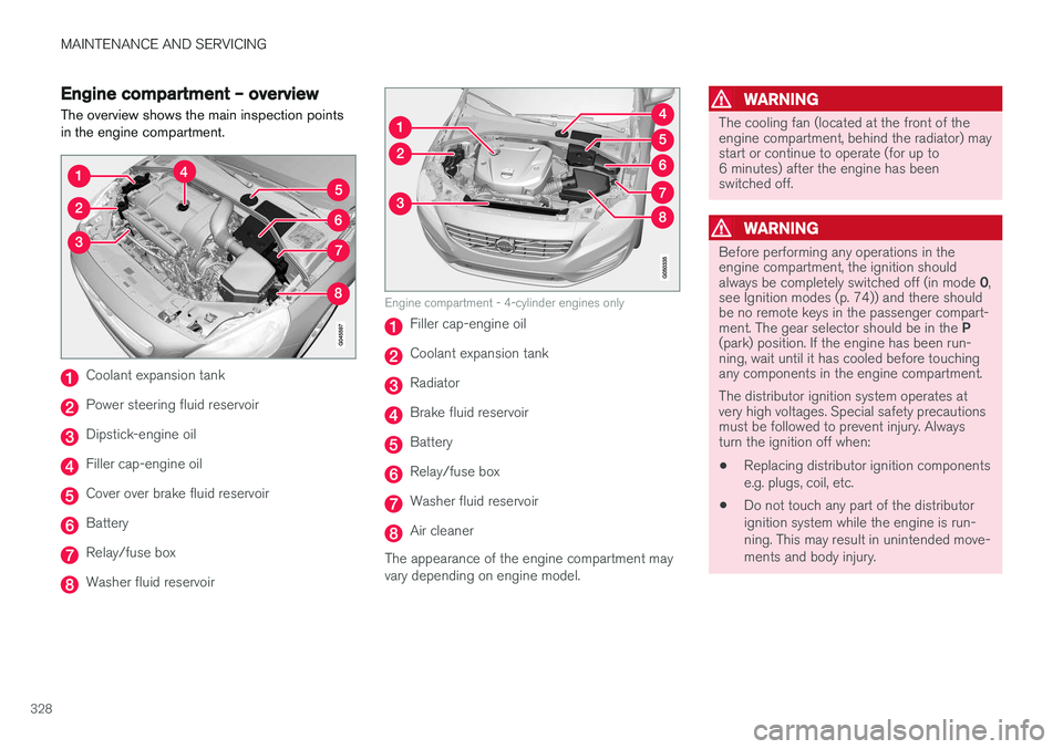
Engine compartment – overviewThe overview shows the main inspection points in the engine compartment.
Coolant expansion tank
Power steering fluid reservoir
Dipstick-engine oil
Filler cap-engine oil
Cover over brake fluid reservoir
Battery
Relay/fuse box
Washer fluid reservoir
Engine compartment - 4-cylinder engines only
Filler cap-engine oil
Coolant expansion tank
Radiator
Brake fluid reservoir
Battery
Relay/fuse box
Washer fluid reservoir
Air cleaner
The appearance of the engine compartment may vary depending on engine model.
WARNING
The cooling fan (located at the front of the engine compartment, behind the radiator) maystart or continue to operate (for up to6 minutes) after the engine has beenswitched off.
WARNING
Before performing any operations in the engine compartment, the ignition should always be completely switched off (in mode 0,
see Ignition modes (p. 74)) and there should be no remote keys in the passenger compart- ment. The gear selector should be in the P
(park) position. If the engine has been run- ning, wait until it has cooled before touchingany components in the engine compartment. The distributor ignition system operates at very high voltages. Special safety precautionsmust be followed to prevent injury. Alwaysturn the ignition off when:
• Replacing distributor ignition components e.g. plugs, coil, etc.
• Do not touch any part of the distributorignition system while the engine is run-ning. This may result in unintended move-ments and body injury.
Page 337 of 394
MAINTENANCE AND SERVICING
}}
* Option/accessory.335
WARNING
•The engine should not be running when changing bulbs.
• If the engine has been running just priorto replacing bulbs in the headlight hous-ing, please keep in mind that componentsin the engine compartment will be hot.
WARNING
•
Active Bending Lights
* – due to the high
voltage used by these headlights, these bulbs should only be replaced by atrained and qualified Volvo service techni-cian.
• Turn off the lights and remove the remotekey from the ignition before changing anybulbs.
Related information
•Bulbs – headlight housing (p. 335)
• Bulbs – taillight housing (p. 340)
• Bulbs – vanity mirror lighting (p. 341)
• Bulbs – license plate lighting (p. 340)
Bulbs – headlight housing
The entire headlight housing must be lifted out when replacing all front bulbs.
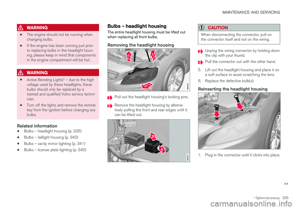
Removing the headlight housing
Pull out the headlight housing's locking pins.
Remove the headlight housing by alterna- tively pulling the front and rear edges until itcan be lifted out.
CAUTION
When disconnecting the connector, pull on the connector itself and not on the wiring.
Unplug the wiring connector by holding down the clip with your thumb.
Pull the connector out with the other hand.
5. Lift out the headlight housing and place it on a soft surface to avoid scratching the lens.
6. Replace the defective bulb(s).
Reinserting the headlight housing
1. Plug in the connector until it clicks into place.
Page 338 of 394
||
MAINTENANCE AND SERVICING
3362. Reinstall the headlight housing and locking
pins. The short locking pin should be closest to the grille. Check that they are correctlyinserted. The headlight housing must be properly in place and the wiring connector correctlyreconnected before the lighting is switchedon or the remote key is inserted into the igni-tion slot.
3. Check that the lights function properly.
Related information
• Bulbs – introduction (p. 334)
• Bulbs – cover (p. 336)
• Bulbs – specifications (p. 341)
Bulbs – cover The larger cover has to be removed in order to change the high/low beam headlight bulbs.
Removing the cover to access the
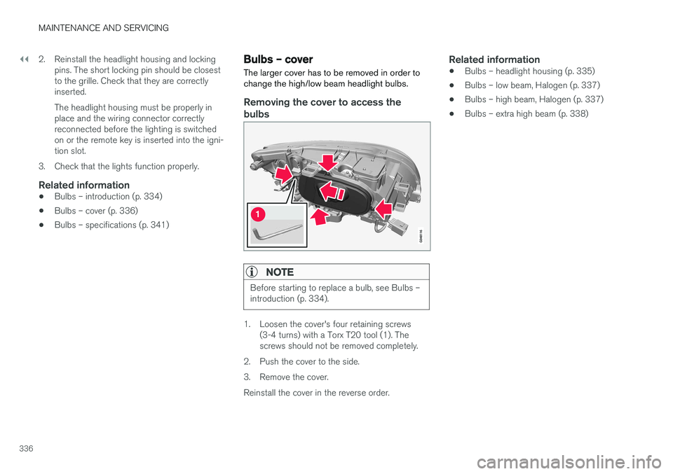
bulbs
NOTE
Before starting to replace a bulb, see Bulbs – introduction (p. 334).
1. Loosen the cover's four retaining screws (3-4 turns) with a Torx T20 tool (1). The screws should not be removed completely.
2. Push the cover to the side.
3. Remove the cover.Reinstall the cover in the reverse order.
Related information
• Bulbs – headlight housing (p. 335)
• Bulbs – low beam, Halogen (p. 337)
• Bulbs – high beam, Halogen (p. 337)
• Bulbs – extra high beam (p. 338)