change wheel VOLVO S60 CROSS COUNTRY 2018 Owner´s Manual
[x] Cancel search | Manufacturer: VOLVO, Model Year: 2018, Model line: S60 CROSS COUNTRY, Model: VOLVO S60 CROSS COUNTRY 2018Pages: 394, PDF Size: 9.41 MB
Page 4 of 394
2
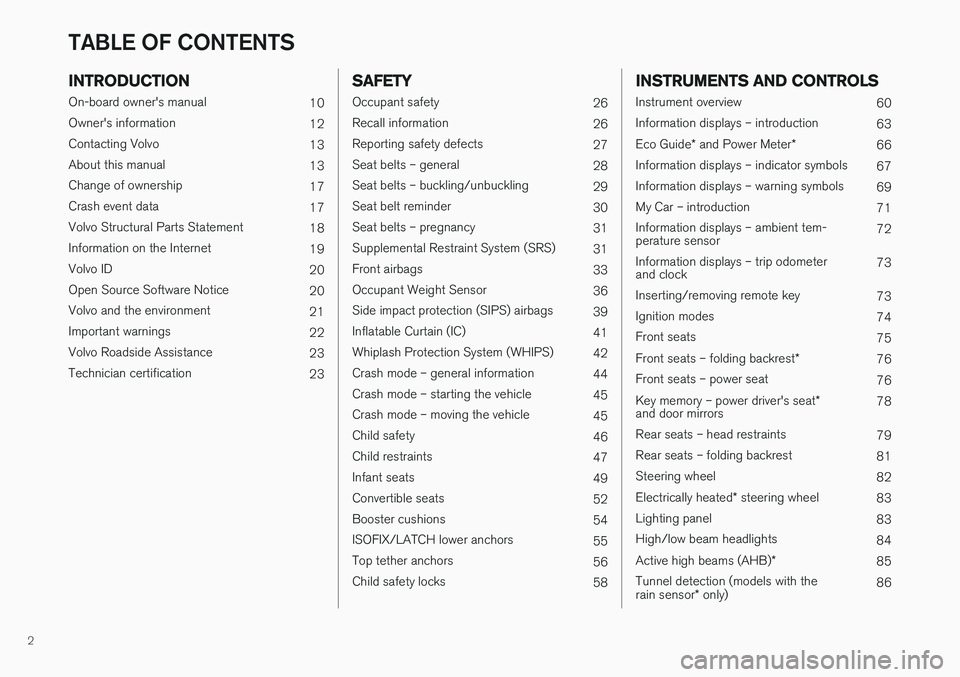
INTRODUCTION
On-board owner's manual10
Owner's information 12
Contacting Volvo 13
About this manual 13
Change of ownership 17
Crash event data 17
Volvo Structural Parts Statement 18
Information on the Internet 19
Volvo ID 20
Open Source Software Notice 20
Volvo and the environment 21
Important warnings 22
Volvo Roadside Assistance 23
Technician certification 23
SAFETY
Occupant safety26
Recall information 26
Reporting safety defects 27
Seat belts – general 28
Seat belts – buckling/unbuckling 29
Seat belt reminder 30
Seat belts – pregnancy 31
Supplemental Restraint System (SRS) 31
Front airbags 33
Occupant Weight Sensor 36
Side impact protection (SIPS) airbags 39
Inflatable Curtain (IC) 41
Whiplash Protection System (WHIPS) 42
Crash mode – general information 44
Crash mode – starting the vehicle 45
Crash mode – moving the vehicle 45
Child safety 46
Child restraints 47
Infant seats 49
Convertible seats 52
Booster cushions 54
ISOFIX/LATCH lower anchors 55
Top tether anchors 56
Child safety locks 58
INSTRUMENTS AND CONTROLS
Instrument overview 60
Information displays – introduction 63
Eco Guide * and Power Meter *
66
Information displays – indicator symbols 67
Information displays – warning symbols 69
My Car – introduction 71
Information displays – ambient tem- perature sensor 72
Information displays – trip odometerand clock 73
Inserting/removing remote key 73
Ignition modes 74
Front seats 75
Front seats – folding backrest *
76
Front seats – power seat 76
Key memory – power driver's seat *
and door mirrors 78
Rear seats – head restraints 79
Rear seats – folding backrest 81
Steering wheel 82
Electrically heated * steering wheel
83
Lighting panel 83
High/low beam headlights 84
Active high beams (AHB) *
85
Tunnel detection (models with the rain sensor * only) 86
TABLE OF CONTENTS
Page 66 of 394
||
INSTRUMENTS AND CONTROLS
* Option/accessory.
64
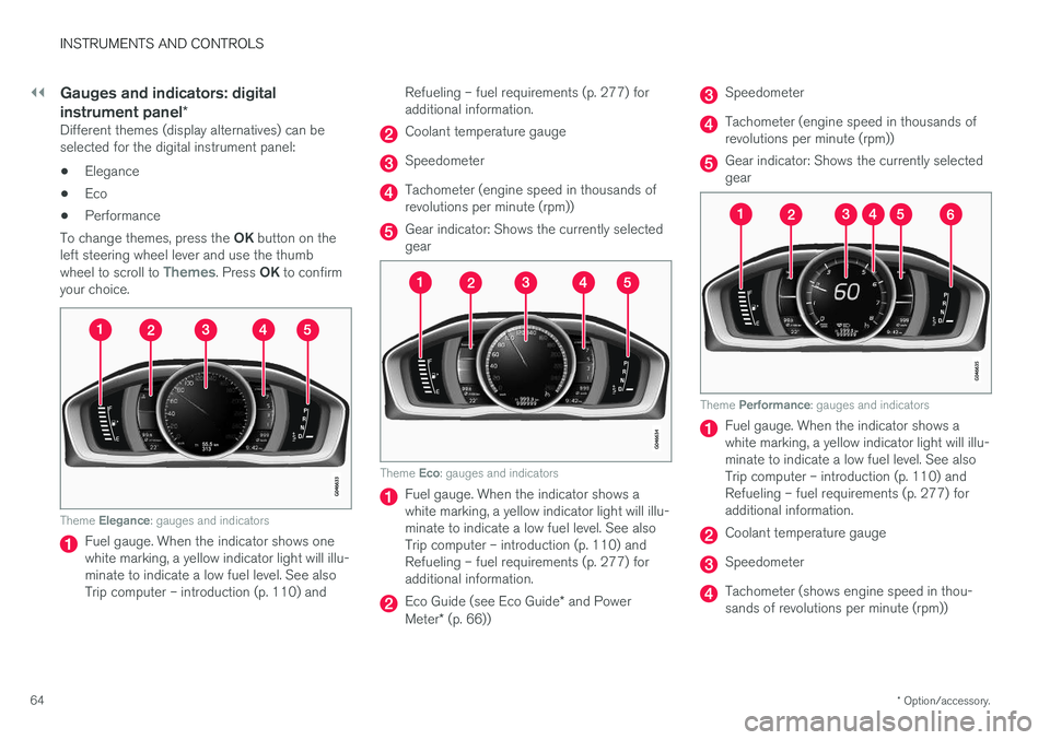
Gauges and indicators: digital instrument panel *
Different themes (display alternatives) can be selected for the digital instrument panel:
• Elegance
• Eco
• Performance
To change themes, press the OK button on the
left steering wheel lever and use the thumb wheel to scroll to
Themes. Press OK to confirm
your choice.
Theme Elegance : gauges and indicators
Fuel gauge. When the indicator shows one white marking, a yellow indicator light will illu-minate to indicate a low fuel level. See alsoTrip computer – introduction (p. 110) and Refueling – fuel requirements (p. 277) foradditional information.
Coolant temperature gauge
Speedometer
Tachometer (engine speed in thousands of revolutions per minute (rpm))
Gear indicator: Shows the currently selected gear
Theme
Eco: gauges and indicators
Fuel gauge. When the indicator shows a white marking, a yellow indicator light will illu-minate to indicate a low fuel level. See alsoTrip computer – introduction (p. 110) andRefueling – fuel requirements (p. 277) foradditional information.
Eco Guide (see Eco Guide * and Power
Meter * (p. 66))
Speedometer
Tachometer (engine speed in thousands of revolutions per minute (rpm))
Gear indicator: Shows the currently selected gear
Theme Performance : gauges and indicators
Fuel gauge. When the indicator shows a white marking, a yellow indicator light will illu-minate to indicate a low fuel level. See alsoTrip computer – introduction (p. 110) andRefueling – fuel requirements (p. 277) foradditional information.
Coolant temperature gauge
Speedometer
Tachometer (shows engine speed in thou- sands of revolutions per minute (rpm))
Page 87 of 394

INSTRUMENTS AND CONTROLS
}}}}
* Option/accessory.85
Active high beams (AHB) *
AHB uses a camera at the upper edge of the windshield to detect the headlights of oncomingvehicles or the taillights of a vehicle directlyahead. When this happens, the headlights willautomatically switch from high beams to lowbeams. When the camera no longer detects theheadlights/taillights of other vehicles, your head-lights will switch back to high beams after sev-eral seconds.
To activate AHB:
• Turn the headlight control to the
posi-
tion.
The feature will begin functioning if the engine has been running for at least 20 seconds and thevehicle's speed is at least 12 mph (20 km/h).
Headlight switch in the AUTO position
Switch AHB on or off by pulling the left steering wheel lever rearward (toward the steering wheel)as far as possible and releasing it. If AHB isswitched off while the high beams are on, theheadlights will change to low beams.
Models with an analog instrument panel
When AHB is activated, the symbol will
illuminate in the instrument panel. The high beam indicator (
) in the instrument panel will also
illuminate when the high beams are on.
Models with a digital instrument panel
When AHB is activated, will illuminate as a
white symbol in the instrument panel. When the
high beams are on, the symbol will change to blue.
NOTE
• Keep the windshield in front of the cam- era free of ice, snow, dirt, etc.
• Do not mount or in any way attach any-thing on the windshield that couldobstruct the camera.
If Active high beam Temporary unavailable
Switch manually is displayed in the instrument
panel, switching between high and low beams will have to be done manually. However, the light switch can remain in the
position. The
same applies if Windscreen Sensors blocked
is displayed and the symbol is displayed.
The
symbol will go out when these mes-
sages are displayed. AHB may be temporarily unavailable (e.g., in heavy fog or rain). When AHB becomes activeagain or if the sensors in the windshield are nolonger obscured, the messages will disappear and the
symbol will illuminate.
CAUTION
In the following situations, it may be neces- sary to switch between high and low beamsmanually:
• In heavy fog or rain
• In blowing snow or slush
Page 114 of 394
||
INSTRUMENTS AND CONTROLS
112
FunctionDescription
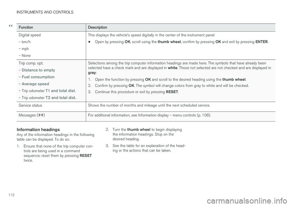
Digital speed – km/h – mph– None This displays the vehicle's speed digitally in the center of the instrument panel •
Open by pressing
OK, scroll using the thumb wheel, confirm by pressing OK and exit by pressing ENTER.
Trip comp. opt. –
Distance to empty
– Fuel consumption
– Average speed
– Trip odometer T1 and total dist.
– Trip odometer T2 and total dist.
Selections among the trip computer information headings are made here. The symbols that have already been selected have a check mark and are displayed in white. Those not selected are not checked and are displayed in
gray :
1. Open the function by pressing OK and scroll to the desired heading using the thumb wheel.
2. Confirm by pressing OK. The symbol will change colors from gray to white and will be checked.
3. Continue this procedure or exit by pressing RESET.
Service status Shows the number of months and mileage until the next scheduled service.
Messages (##) For additional information, see Information display – menu controls (p. 108).
Information headingsAny of the information headings in the following table can be displayed. To do so:
1. Ensure that none of the trip computer con-
trols are being used in a command sequence; reset them by pressing RESET
twice. 2.
Turn the thumb wheel to begin displaying
the information headings. Stop on the desired heading.
3. See the table for an explanation of the head- ing or the actions that can be taken.
Page 117 of 394
INSTRUMENTS AND CONTROLS
115
FunctionDescription
Contrast mode /Color mode Adjust the instrument panel's contrast and color.
Service status Shows the number of months and mileage until the next scheduled service.
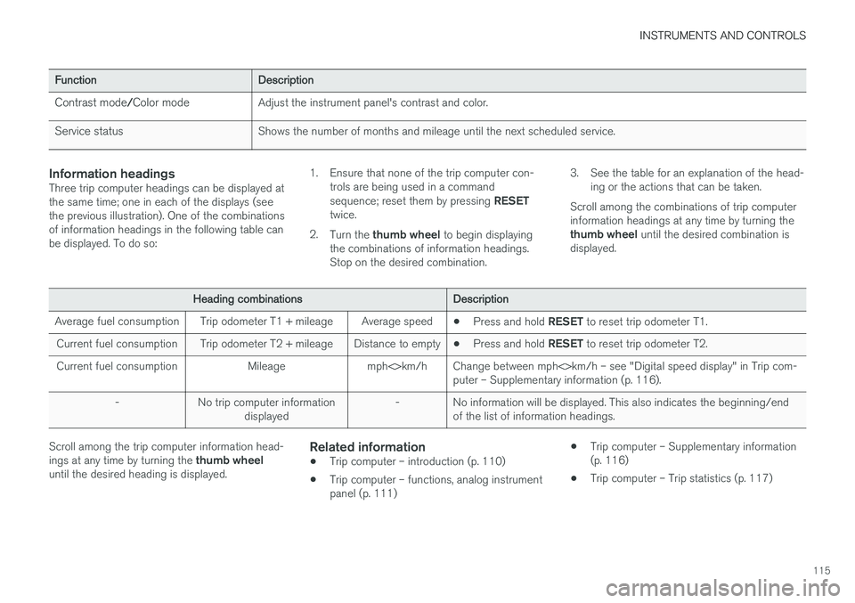
Information headingsThree trip computer headings can be displayed at the same time; one in each of the displays (seethe previous illustration). One of the combinationsof information headings in the following table canbe displayed. To do so: 1. Ensure that none of the trip computer con-
trols are being used in a command sequence; reset them by pressing RESET
twice.
2. Turn the thumb wheel to begin displaying
the combinations of information headings. Stop on the desired combination. 3. See the table for an explanation of the head-
ing or the actions that can be taken.
Scroll among the combinations of trip computerinformation headings at any time by turning the thumb wheel until the desired combination is
displayed.
Heading combinations Description
Average fuel consumption Trip odometer T1 + mileage Average speed •Press and hold
RESET to reset trip odometer T1.
Current fuel consumption Trip odometer T2 + mileage Distance to empty •Press and hold
RESET to reset trip odometer T2.
Current fuel consumption Mileage mph<>km/h Change between mph<>km/h – see "Digital speed display" in Trip com- puter – Supplementary information (p. 116).
- No trip computer information displayed - No information will be displayed. This also indicates the beginning/end
of the list of information headings.
Scroll among the trip computer information head- ings at any time by turning the thumb wheel
until the desired heading is displayed.Related information
• Trip computer – introduction (p. 110)
• Trip computer – functions, analog instrument panel (p. 111) •
Trip computer – Supplementary information(p. 116)
• Trip computer – Trip statistics (p. 117)
Page 118 of 394

INSTRUMENTS AND CONTROLS
* Option/accessory.
116
Trip computer – Supplementary information
General information for both Analog and Digital trip computer functions.
Average fuel consumptionFuel consumption since the last time this func- tion was reset.
Average speedThe vehicle's average speed since the last timethis function was reset.
Current fuel consumptionCurrent fuel consumption is calculated approxi-mately once a second. When the vehicle is mov-ing at low speed, fuel consumption is displayedper unit of time. At higher speeds, it is displayedin terms of distance. Miles or kilometers can be displayed, see the heading "Changing units".
Distance to emptyThis function shows the approximate distancethat can be driven on the fuel remaining in the tank. When
Distance to empty shows "----",
there is very little useable fuel remaining in that tank; refuel as soon as possible. The calculationis based on average fuel consumption during thelast 20 miles (30 km) of driving and the amountof fuel remaining in the tank (the accuracy of thisfigure may vary if your driving style changes). An economical driving style will generally increasethis distance. See Economical driving (p. 282) for information about driving economically.
Digital speed display
*Speed is expressed in the unit not used by theinstrument panel's speedometer e.g., if the nor-mal speedometer is in mph, the trip computer willdisplay in the speed in km/h and vice versa.
Resetting an analog instrument panel
Trip odometer(s) and average speed
1. Display trip odometer T1 or T1, or Average
speed.
2. Press and hold RESET until selected func-
tion is reset.
Each trip computer heading must be reset indi- vidually.
Resetting a digital instrument panel
Trip odometer
1. Turn the thumb wheel to select the combi-
nation of headings containing the trip odom- eter to be reset.
2. Press and hold RESET until selected trip
odometer is reset.
Average speed and fuel consumption
1. Select Trip computer reset and press OK. 2. Select one of the following alternatives using
the thumb wheel and press OK:
• mpg
• mph
• Reset both
3. Finish by pressing RESET.
Changing unitsTo change the unit (miles/km) used to measure distance and speed, go to
MY CARSettings
System optionsDistance and fuel units.
NOTE
In addition to changing units in the trip com- puter, this also changes the units used in the Volvo Navigation System (VNS) *.
Related information
• Trip computer – introduction (p. 110)
• Trip computer – functions, analog instrument panel (p. 111)
• Trip computer – functions, digital instrumentpanel (p. 114)
• Trip computer – Trip statistics (p. 117)
Page 150 of 394
||
LOCKS AND ALARM
* Option/accessory.
148
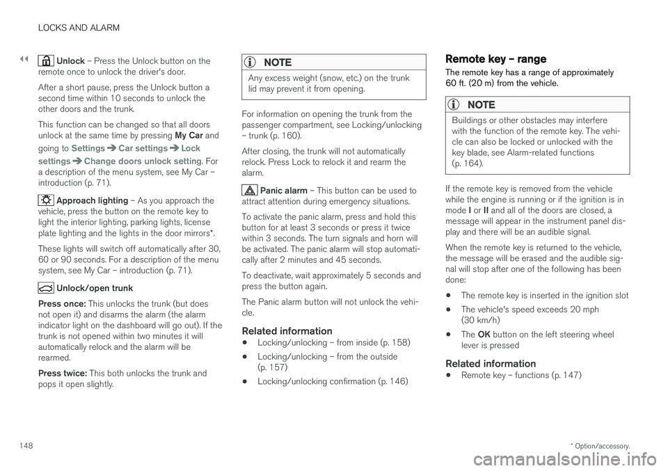
Unlock – Press the Unlock button on the
remote once to unlock the driver's door. After a short pause, press the Unlock button a second time within 10 seconds to unlock theother doors and the trunk. This function can be changed so that all doors unlock at the same time by pressing My Car and
going to
SettingsCar settingsLock
settings
Change doors unlock setting. For
a description of the menu system, see My Car – introduction (p. 71).
Approach lighting – As you approach the
vehicle, press the button on the remote key to light the interior lighting, parking lights, license plate lighting and the lights in the door mirrors *.
These lights will switch off automatically after 30, 60 or 90 seconds. For a description of the menusystem, see My Car – introduction (p. 71).
Unlock/open trunk
Press once: This unlocks the trunk (but does
not open it) and disarms the alarm (the alarm indicator light on the dashboard will go out). If thetrunk is not opened within two minutes it willautomatically relock and the alarm will berearmed. Press twice: This both unlocks the trunk and
pops it open slightly.
NOTE
Any excess weight (snow, etc.) on the trunk lid may prevent it from opening.
For information on opening the trunk from the passenger compartment, see Locking/unlocking– trunk (p. 160). After closing, the trunk will not automatically relock. Press Lock to relock it and rearm thealarm.
Panic alarm – This button can be used to
attract attention during emergency situations. To activate the panic alarm, press and hold this button for at least 3 seconds or press it twicewithin 3 seconds. The turn signals and horn willbe activated. The panic alarm will stop automati-cally after 2 minutes and 45 seconds. To deactivate, wait approximately 5 seconds and press the button again. The Panic alarm button will not unlock the vehi- cle.
Related information
• Locking/unlocking – from inside (p. 158)
• Locking/unlocking – from the outside(p. 157)
• Locking/unlocking confirmation (p. 146)
Remote key – range The remote key has a range of approximately 60 ft. (20 m) from the vehicle.
NOTE
Buildings or other obstacles may interfere with the function of the remote key. The vehi-cle can also be locked or unlocked with thekey blade, see Alarm-related functions(p. 164).
If the remote key is removed from the vehicle while the engine is running or if the ignition is in mode
I or II and all of the doors are closed, a
message will appear in the instrument panel dis- play and there will be an audible signal. When the remote key is returned to the vehicle, the message will be erased and the audible sig-nal will stop after one of the following has beendone:
• The remote key is inserted in the ignition slot
• The vehicle's speed exceeds 20 mph(30 km/h)
• The
OK button on the left steering wheel
lever is pressed
Related information
• Remote key – functions (p. 147)
Page 172 of 394
DRIVER SUPPORT
* Option/accessory.
170
Adjustable steering force *
Steering force increases with the speed of the vehicle to give the driver enhanced sense ofcontrol and stability. At low speed the vehicle iseasy to steer in order to facilitate parking, etc.
Adjustable steering force *Steering force can be changed under MY CAR
Car settingsSteering wheel force.
Select Low, Medium or High. For a description
of the menu system, My Car – introduction (p. 71).
NOTE
This steering force level menu function can- not be accessed when the vehicle is inmotion.
NOTE
In certain situations, the power steering may become too warm and will have to be tempo-rarily cooled down. While this is happening,the power steering effect will be reducedslightly and somewhat more effort may berequired to turn the steering wheel. If this occurs, a message will be displayed in the instrument panel.
Road Sign Information (RSI) * –
introduction
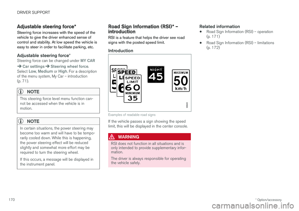
RSI is a feature that helps the driver see road signs with the posted speed limit.
Introduction
Examples of readable road signs
If the vehicle passes a sign showing the speed limit, this will be displayed in the center console.
WARNING
RSI does not function in all situations and is only intended to provide supplementary infor-mation. The driver is always responsible for operating the vehicle safely.
Related information
• Road Sign Information (RSI) – operation (p. 171)
• Road Sign Information (RSI) – limitations(p. 172)
Page 243 of 394
DRIVER SUPPORT
}}
241
DeactivationMove the gear selector from R to another gear.
The camera remains active for approx. 5 seconds after the gear selector has been moved from R or
until the vehicle's forward speed exceeds 6 mph/10 km/h (21 mph/35 km/h in reverse).The screen will then revert to the view that was displayed before R was selected.
NOTE
If any button on the center console control panel is pressed, the camera image will disap- pear from the display. Pressing CAM will
return the camera image to the display.
SettingsBy default, PAC is set to activate when the gear selector is moved to R
To change PAC settings when a camera view is displayed: 1. Press OK/MENU when a camera view is on
the screen. A menu will be displayed.
2. Turn TUNE to scroll to the desired setting.
3. Press OK/MENU to make the setting and
exit the menu by pressing EXIT.
Summary
•Pressing
CAM will activate the camera even
if the gear selector is not in Reverse.
• Toggle between normal view and zoom by pressing
CAM or by turning TUNE.
Related information
•Park assist – introduction (p. 230)
• Park assist – function (p. 230)
• Park assist – troubleshooting (p. 238)
• Park assist – limitations (p. 233)
• Rear Park Assist Camera (PAC) – introduc- tion (p. 239)
Rear Park Assist Camera (PAC) – guiding and marker lines
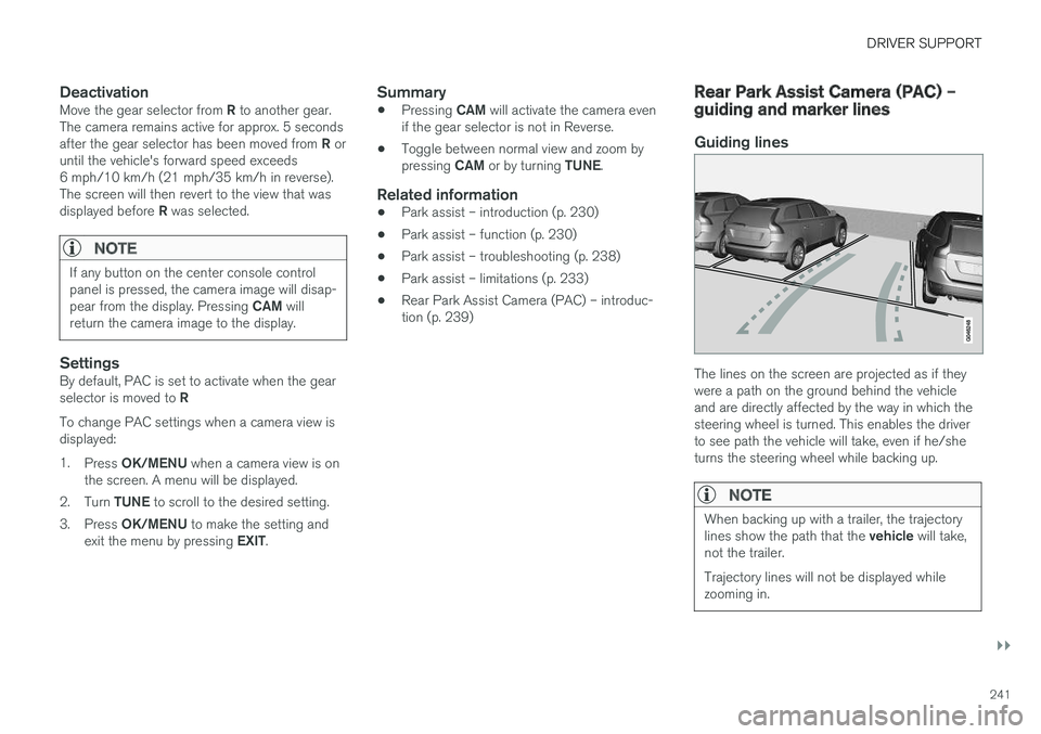
Guiding lines
The lines on the screen are projected as if they were a path on the ground behind the vehicleand are directly affected by the way in which thesteering wheel is turned. This enables the driverto see path the vehicle will take, even if he/sheturns the steering wheel while backing up.
NOTE
When backing up with a trailer, the trajectory lines show the path that the
vehicle will take,
not the trailer. Trajectory lines will not be displayed while zooming in.
Page 260 of 394
||
STARTING AND DRIVING
* Option/accessory.
258
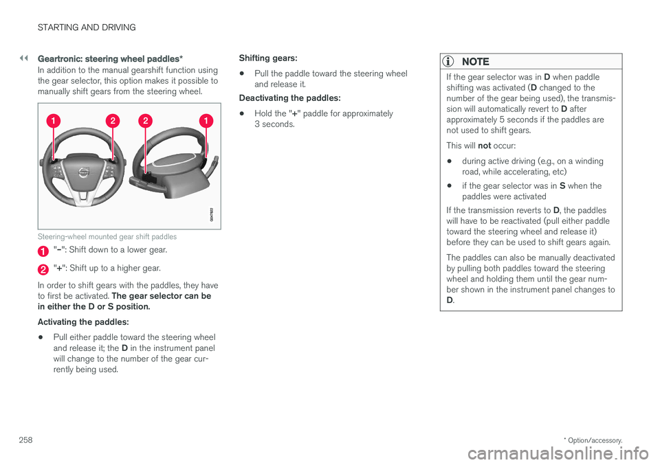
Geartronic : steering wheel paddles *
In addition to the manual gearshift function using the gear selector, this option makes it possible tomanually shift gears from the steering wheel.
Steering-wheel mounted gear shift paddles
"– ": Shift down to a lower gear.
"+ ": Shift up to a higher gear.
In order to shift gears with the paddles, they have to first be activated. The gear selector can be
in either the D or S position. Activating the paddles:
• Pull either paddle toward the steering wheel and release it; the
D in the instrument panel
will change to the number of the gear cur- rently being used. Shifting gears:
• Pull the paddle toward the steering wheeland release it.
Deactivating the paddles:
• Hold the "
+" paddle for approximately
3 seconds.
NOTE
If the gear selector was in D when paddle
shifting was activated ( D changed to the
number of the gear being used), the transmis- sion will automatically revert to D after
approximately 5 seconds if the paddles are not used to shift gears. This will not occur:
• during active driving (e.g., on a winding road, while accelerating, etc)
• if the gear selector was in
S when the
paddles were activated
If the transmission reverts to D, the paddles
will have to be reactivated (pull either paddletoward the steering wheel and release it)before they can be used to shift gears again. The paddles can also be manually deactivated by pulling both paddles toward the steeringwheel and holding them until the gear num-ber shown in the instrument panel changes to D .