coolant VOLVO S60 INSCRIPTION 2016 Owner´s Manual
[x] Cancel search | Manufacturer: VOLVO, Model Year: 2016, Model line: S60 INSCRIPTION, Model: VOLVO S60 INSCRIPTION 2016Pages: 344, PDF Size: 7.24 MB
Page 10 of 344
Contents
8
10
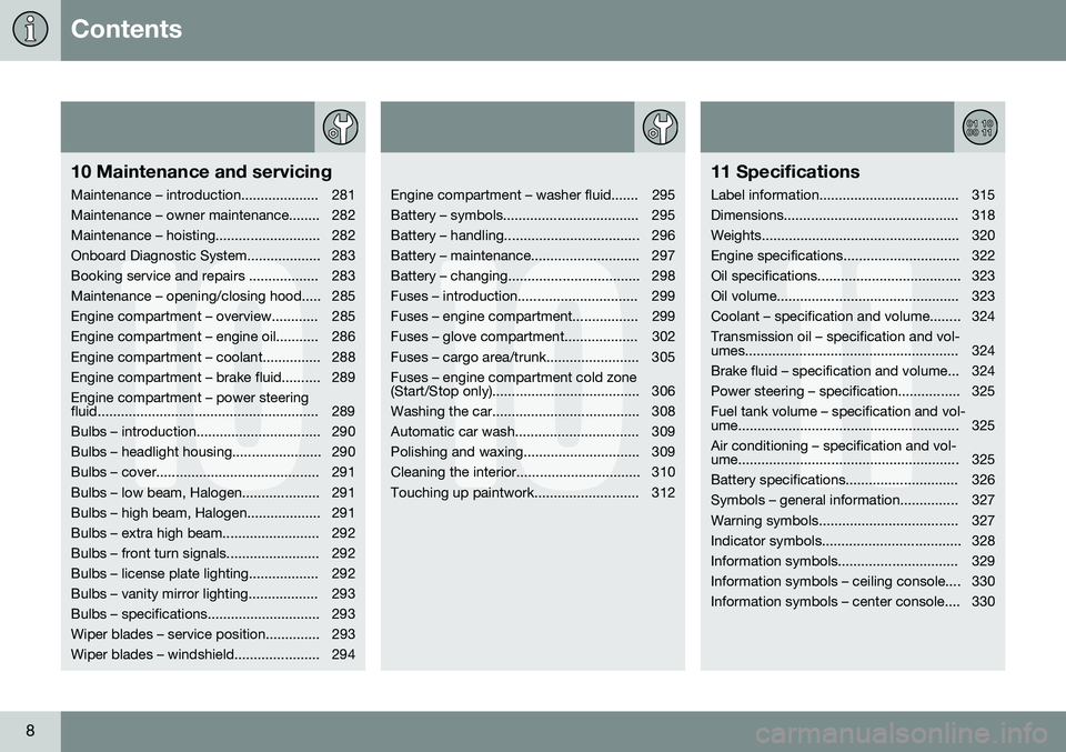
10 Maintenance and servicing
Maintenance – introduction.................... 281
Maintenance – owner maintenance........ 282
Maintenance – hoisting........................... 282
Onboard Diagnostic System................... 283
Booking service and repairs .................. 283
Maintenance – opening/closing hood..... 285
Engine compartment – overview............ 285
Engine compartment – engine oil........... 286
Engine compartment – coolant............... 288
Engine compartment – brake fluid.......... 289Engine compartment – power steering
fluid......................................................... 289
Bulbs – introduction................................ 290
Bulbs – headlight housing....................... 290
Bulbs – cover.......................................... 291
Bulbs – low beam, Halogen.................... 291
Bulbs – high beam, Halogen................... 291
Bulbs – extra high beam......................... 292
Bulbs – front turn signals........................ 292
Bulbs – license plate lighting.................. 292
Bulbs – vanity mirror lighting.................. 293
Bulbs – specifications............................. 293
Wiper blades – service position.............. 293
Wiper blades – windshield...................... 294
10
Engine compartment – washer fluid....... 295
Battery – symbols................................... 295
Battery – handling................................... 296
Battery – maintenance............................ 297
Battery – changing.................................. 298
Fuses – introduction............................... 299
Fuses – engine compartment................. 299
Fuses – glove compartment................... 302
Fuses – cargo area/trunk........................ 305Fuses – engine compartment cold zone
(Start/Stop only)...................................... 306
Washing the car...................................... 308
Automatic car wash................................ 309
Polishing and waxing.............................. 309
Cleaning the interior................................ 310
Touching up paintwork........................... 312
11
11 Specifications
Label information.................................... 315
Dimensions............................................. 318
Weights................................................... 320
Engine specifications.............................. 322
Oil specifications..................................... 323
Oil volume............................................... 323
Coolant – specification and volume........ 324Transmission oil – specification and vol-
umes....................................................... 324
Brake fluid – specification and volume... 324
Power steering – specification................ 325Fuel tank volume – specification and vol-
ume......................................................... 325 Air conditioning – specification and vol-
ume......................................................... 325
Battery specifications............................. 326
Symbols – general information............... 327
Warning symbols.................................... 327
Indicator symbols.................................... 328
Information symbols............................... 329
Information symbols – ceiling console.... 330
Information symbols – center console.... 330
Page 18 of 344
||
01 Introduction
01
16
Types of lists used in the owner'sinformation
ProceduresProcedures (step-by-step instructions), or actions that must be carried out in a certainorder, are arranged in numbered lists in thismanual.
If there is a series of illustrations associ- ated with step-by-step instructions, eachstep in the procedure is numbered in thesame way as the corresponding illustra-tion.
Lists in which letters are used can be found with series of illustrations in caseswhere the order in which the instructionsare carried out is not important.
Arrows with or without numbers are used to indicate the direction of a movement.
Arrows containing letters are used to indi- cate movement.
If there are no illustrations associated with astep-by-step list, the steps in the procedureare indicated by ordinary numbers.
Position listsRed circles containing a number are used in general overview illustrations in whichcertain components are pointed out. Thecorresponding number is also used in theposition list's description of the variouscomponents.
Bullet listsBullets are used to differentiate a number of components/functions/points of informationthat can be listed in random order. For example:
• Coolant
• Engine oil
Continues on next page
}
}This symbol can be found at the lower
right corner to indicate that the current topic continues on the following page.
Continuation from previous page
| | This symbol can be found at the upper left
corner to indicate that the current topic is a continuation from the previous page.
Options and accessoriesOptional or accessory equipment describedin this manual is indicated by an asterisk. Optional or accessory equipment may not be available in all countries or markets. Pleasenote that some vehicles may be equipped dif-ferently, depending on special legal require-ments. Contact your Volvo retailer for additional information.
NOTE
• Do not export your Volvo to another country before investigating that coun-try's applicable safety and exhaustemission requirements. In some casesit may be difficult or impossible tocomply with these requirements. Mod-ifications to the emission control sys-tem(s) may render your Volvo not certi-fiable for legal operation in the U.S.,Canada and other countries.
• All information, illustrations and speci-fications contained in this manual arebased on the latest product informa-tion available at the time of publica-tion. Please note that some vehiclesmay be equipped differently, depend-ing on special legal requirements.Optional equipment described in thismanual may not be available in all mar-kets.
• Some of the illustrations shown aregeneric and may not depict the exactmodel for which this manual isintended.
• Volvo reserves the right to make modelchanges at any time, or to changespecifications or design without noticeand without incurring obligation.
Page 61 of 344
03 Instruments and controls
03
}}
* Option/accessory, for more information, see Introduction.59
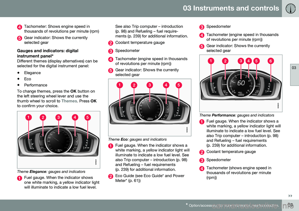
Tachometer: Shows engine speed in thousands of revolutions per minute (rpm)
Gear indicator: Shows the currently selected gear
Gauges and indicators: digital instrument panel*
Different themes (display alternatives) can be selected for the digital instrument panel: • Elegance
• Eco
• Performance
To change themes, press the OK button on
the left steering wheel lever and use the thumb wheel to scroll to
Themes. Press OK
to confirm your choice.
Theme Elegance : gauges and indicators
Fuel gauge. When the indicator shows one white marking, a yellow indicator lightwill illuminate to indicate a low fuel level. See also Trip computer – introduction(p. 98) and Refueling – fuel require-ments (p. 239) for additional information.
Coolant temperature gauge
Speedometer
Tachometer (engine speed in thousands of revolutions per minute (rpm))
Gear indicator: Shows the currently selected gear
Theme
Eco: gauges and indicators
Fuel gauge. When the indicator shows a white marking, a yellow indicator light willilluminate to indicate a low fuel level. Seealso Trip computer – introduction (p. 98)and Refueling – fuel requirements(p. 239) for additional information.
Eco Guide (see Eco Guide* and Power Meter* (p. 61))
Speedometer
Tachometer (engine speed in thousands of revolutions per minute (rpm))
Gear indicator: Shows the currently selected gear
Theme Performance : gauges and indicators
Fuel gauge. When the indicator shows a white marking, a yellow indicator light willilluminate to indicate a low fuel level. Seealso Trip computer – introduction (p. 98)and Refueling – fuel requirements(p. 239) for additional information.
Coolant temperature gauge
Speedometer
Tachometer (shows engine speed in thousands of revolutions per minute(rpm))
Page 67 of 344
03 Instruments and controls
03
}}
65
Generator not chargingThis symbol comes on during driving if a fault has occurred in the electrical system. Contactan authorized Volvo workshop.
Engine temperatureEngine overheating can result from low oil or coolant levels, towing or hard driving at highheat and altitude, or mechanical malfunction.Engine overheating will be signaled with textand a red warning triangle in the middle of theinstrument display. The exact text will dependon the degree of overheating. It may range from
High engine temp Reduce speed toHigh engine temp Stop engine. If appropri-
ate, other messages, such as Coolant level
low, Stop safely will also be displayed. If
your engine does overheat so that you must stop the engine, always allow the engine tocool before attempting to check oil and cool-ant levels. See Engine compartment – coolant (p. 288) for more information.
Fault in brake systemIf this symbol lights, the brake fluid level may be too low. Stop the vehicle in a safe placeand check the level in the brake fluid reser-voir, see Engine compartment – brake fluid(p. 289). If the level in the reservoir is belowMIN , the vehicle should be transported to an
authorized Volvo workshop to have the brakesystem checked. If the
and symbols come on
at the same time, there may be a fault in the brake force distribution system.
1. Stop the vehicle in a safe place and turn off the engine.
2. Restart the engine.
• If both symbols extinguish, continue driv- ing.
• If the symbols remain on, check the levelin the brake fluid reservoir, see Enginecompartment – brake fluid (p. 289). If thebrake fluid level is normal but the sym-bols are still lit, the vehicle can be driven,with great care, to an authorized Volvoworkshop to have the brake systemchecked.
• If the level in the reservoir is below
MIN,
the vehicle should be transported to anauthorized Volvo workshop to have thebrake system checked.WARNING
• If the fluid level is below the
MIN mark
in the reservoir or if a warning mes- sage is displayed in the text window:DO NOT DRIVE . Have the vehicle
towed to a trained and qualified Volvoservice technician and have the brakesystem inspected.
• If the
and symbols
are on at the same time, there is a risk of reduced vehicle stability.
Warning symbolThe red warning symbol lights up to indicate a problem related to safety and/or drivability.A message will also appear in the instrumentpanel. The symbol remains visible until thefault has been rectified but the text messagecan be cleared with the OK button, see Infor-
mation display – menu controls (p. 96). Thewarning symbol can also come on in conjunc-tion with other symbols. Action:
1. Stop in a safe place. Do not drive the vehicle further.
2. Read the information on the display. Implement the action in accordance with the message in the display. Clear themessage using OK.
Page 284 of 344
10 Maintenance and servicing
10
282
Maintenance – owner maintenance
Periodic maintenance requirements and inter- vals are described in your vehicle's Warrantyand Service Records Information booklet. The following points can be carried out between the normally scheduled maintenanceservices.
Owner maintenance
Each time the car is refueled:
•Check the engine oil level.
• Clean the windshield, windshield wipers, headlights, and taillights.
Monthly:
• Check cold tire pressure in all tires. Inspect the tires for wear.
• Check that engine coolant and other fluidlevels are between the indicated "min"and "max" markings.
• Clean interior glass surfaces with a glasscleaner and soft paper towels.
• Wipe driver information displays with asoft cloth.
• Visually inspect battery terminals for cor-rosion. Corrosion may indicate a looseterminal connector, or a battery near theend of its useful service life. Consult yourVolvo retailer for additional information.
As needed:Wash the car, including the undercarriage, to reduce wear that can be caused by a buildup of dirt, and corrosion that can be caused bysalt residues. Clean leaves and twigs from air intake vents at the base of the windshield, and from otherplaces where they may collect.
NOTE
Complete service information for qualified technicians is available online for purchaseor subscription at www.volvotechinfo.com.
Related information
•
Maintenance – opening/closing hood (p. 285)
• Engine compartment – overview (p. 285)
• Engine compartment – coolant (p. 288)
• Engine compartment – engine oil (p. 286)
• Engine compartment – power steeringfluid (p. 289)
• Engine compartment – washer fluid(p. 295)
• Cleaning the interior (p. 310)
• Washing the car (p. 308)
• Tire inflation – checking pressure (p. 256)
• Tires – tread wear indicator (p. 251)
Maintenance – hoisting
When the vehicle is hoisted, the jack or garage lift must be positioned in the correctlifting points.
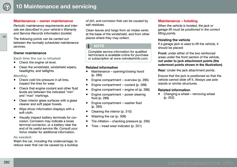
Hoisting the vehicleIf a garage jack is used to lift the vehicle, itshould be placed: Front:
under either of the two reinforced
areas under the front section of the vehicle, not under to jack attachment points (the outermost points shown in the illustration) .
Rear : Under the jack attachment points.
Ensure that the jack is positioned so that the vehicle cannot slide off it. Always use axlestands or similar structures.
Related information
• Changing a wheel – removing wheel (p. 252)
Page 290 of 344
||
10 Maintenance and servicing
10
288
WARNING
Do not allow oil to spill onto or come into contact with hot exhaust pipe surfaces.
Electronically checking the oil levelThe oil level should be checked at regular intervals, particularly during the period up tothe first scheduled maintenance service. To check the oil level:
1. Activate ignition mode II, see Ignition
modes (p. 69).
2. Turn the thumb wheel on the left steering wheel lever until
Oil level is displayed.
> The oil level will be displayed.
NOTE
• The system cannot detect changes in the oil level immediately. The vehiclemust be driven approximately 20 miles(30 km) or have been parked on levelground with the engine off for5 minutes before the oil level readingwill be correct.
• If the necessary conditions are not metfor checking the oil level electronically(time interval after the engine wasswitched off, if the vehicle is parked on an incline, etc.),
No values availablewill be displayed. This does
not indi-
cate a problem with the oil level sen- sor.
Engine compartment – coolant
Normally, the coolant does not need to be changed. If the system must be drained, con-sult a trained and qualified Volvo service tech-nician.
Level check and fillingSee Fuel tank volume – specification and vol-ume (p. 325) for information on cooling sys-tem capacities.
CAUTION
• If necessary, top up the cooling sys- tem with Volvo Genuine Coolant/Anti-freeze only (a 50/50 mix of water andantifreeze).
• Different types of antifreeze/coolantmay not be mixed.
• If the cooling system is drained, itshould be flushed with clean water orpremixed anti-freeze before it is refilledwith the correct mixture of water/anti-freeze.
• The cooling system must always bekept filled to the correct level, and thelevel must be between the
MIN and
MAX marks. If it is not kept filled, there
can be high local temperatures in theengine which could result in damage.Check coolant regularly!
• Do not top up with water only. Thisreduces the rust-protective and anti-freeze qualities of the coolant and hasa lower boiling point. It can also causedamage to the cooling system if itshould freeze.
• Do not use chlorinated tap water in thevehicle's cooling system.
Page 291 of 344
10 Maintenance and servicing
10
289
WARNING
•Never remove the expansion tank cap while the engine is warm. Wait until theengine cools.
• If it is necessary to top off the coolantwhen the engine is warm, unscrew theexpansion tank cap slowly so that theoverpressure dissipates.
Engine compartment – brake fluid
The brake fluid should always be between the MIN
and MAX marks on the inside of the res-
ervoir.
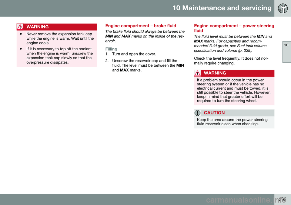
Filling1. Turn and open the cover.
2. Unscrew the reservoir cap and fill the fluid. The level must be between the MIN
and MAX marks.
Engine compartment – power steering fluid
The fluid level must be between the MIN and
MAX marks. For capacities and recom-
mended fluid grade, see Fuel tank volume – specification and volume (p. 325). Check the level frequently. It does not nor- mally require changing.
WARNING
If a problem should occur in the power steering system or if the vehicle has noelectrical current and must be towed, it isstill possible to steer the vehicle. However,keep in mind that greater effort will berequired to turn the steering wheel.
CAUTION
Keep the area around the power steering fluid reservoir clean when checking.
Page 303 of 344
10 Maintenance and servicing
10
301
PosFunctionA
4-cyl. engines: mass air meter, thermostat,EVAP valve10
5-/6-cyl. engines: Injection system, massair meter (6-cyl.engines only), enginecontrol module15
A/C compressor (5-/6- cyl. engines), enginevalves, engine controlmodule (6-cyl.engines), solenoids (6-cyl. non-turbo only),mass air meter (6-cyl.only), oil level sensor(5-cyl. only)10
Engine valves/oil pump/center heatedoxygen sensor (4-cyl.engines)15
Front/rear heated oxy- gen sensors (4-cyl.engines), EVAP valve(5-/6-cyl. engines),heated oxygen sensors(5-/6-cyl. engines)15
PosFunctionA
Oil pump/crankcase ventilation heater/cool-ant pump (5-cyl.engines)10
Ignition coils (4-cyl. engines)15
Fuel leakage detection (5-/6-cyl. engines),control module forradiator shutter (5-cyl.engines)5
Fuel leakage detection, A/C solenoid (4-cyl.engines)7.5
Coolant pump (4-cyl. engines)50
Cooling fan60 (4/5- cyl.engines)
80 (6-cyl. engines)
Power steering100
AThis position is not used on vehicles with the optional Start/Stop function, refer to the table "Engine compart-ment cold zone" in Fuses – engine compartment cold zone(Start/Stop only) (p. 306).
Related information
• Fuses – glove compartment (p. 302)
• Fuses – cargo area/trunk (p. 305)
Page 324 of 344
11 Specifications
11
322
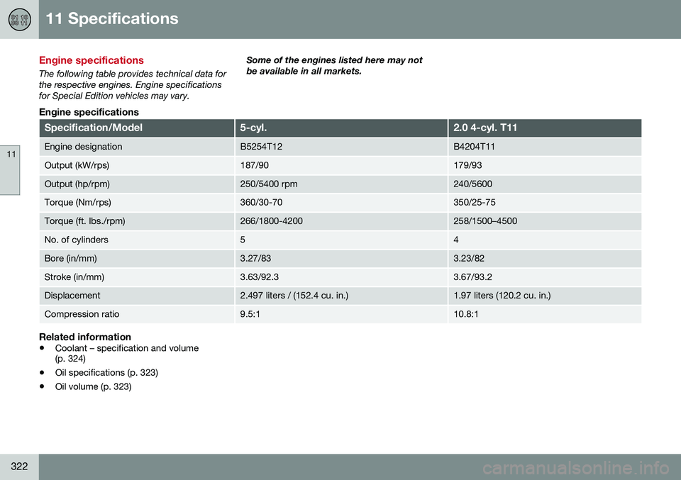
Engine specifications
The following table provides technical data for the respective engines. Engine specificationsfor Special Edition vehicles may vary.Some of the engines listed here may notbe available in all markets.
Engine specifications
Specification/Model5-cyl.2.0 4-cyl. T11
Engine designationB5254T12B4204T11
Output (kW/rps)187/90179/93
Output (hp/rpm)250/5400 rpm240/5600
Torque (Nm/rps)360/30-70350/25-75
Torque (ft. lbs./rpm)266/1800-4200258/1500–4500
No. of cylinders54
Bore (in/mm)3.27/833.23/82
Stroke (in/mm)3.63/92.33.67/93.2
Displacement2.497 liters / (152.4 cu. in.)1.97 liters (120.2 cu. in.)
Compression ratio9.5:110.8:1
Related information
•
Coolant – specification and volume (p. 324)
• Oil specifications (p. 323)
• Oil volume (p. 323)
Page 326 of 344
11 Specifications
11
324
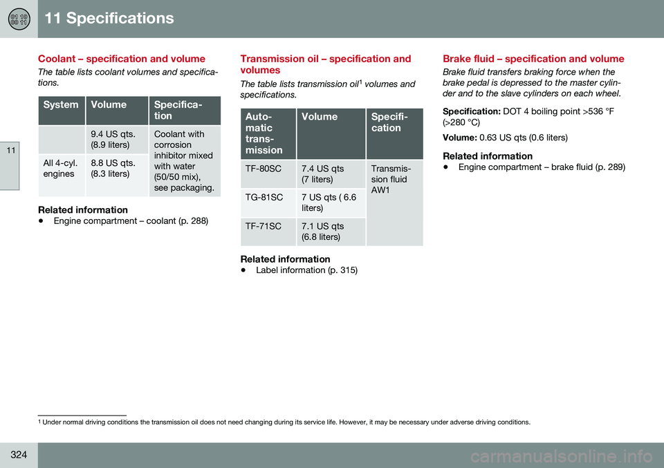
Coolant – specification and volume
The table lists coolant volumes and specifica- tions.
SystemVolumeSpecifica- tion
9.4 US qts. (8.9 liters)Coolant with corrosioninhibitor mixedwith water(50/50 mix),see packaging.
All 4-cyl. engines8.8 US qts. (8.3 liters)
Related information
•Engine compartment – coolant (p. 288)
Transmission oil – specification and volumes
The table lists transmission oil 1
volumes and
specifications.
Auto- matictrans-missionVolumeSpecifi- cation
TF-80SC7.4 US qts (7 liters)Transmis- sion fluidAW1
TG-81SC7 US qts ( 6.6 liters)
TF-71SC7.1 US qts (6.8 liters)
Related information
• Label information (p. 315)
Brake fluid – specification and volume
Brake fluid transfers braking force when the brake pedal is depressed to the master cylin-der and to the slave cylinders on each wheel. Specification:
DOT 4 boiling point >536 °F
(>280 °C) Volume: 0.63 US qts (0.6 liters)
Related information
•Engine compartment – brake fluid (p. 289)
1
Under normal driving conditions the transmission oil does not need changing during its service life. However, it may be necessary under adverse driving conditions.