sport mode VOLVO S60 INSCRIPTION 2016 Owner´s Manual
[x] Cancel search | Manufacturer: VOLVO, Model Year: 2016, Model line: S60 INSCRIPTION, Model: VOLVO S60 INSCRIPTION 2016Pages: 344, PDF Size: 7.24 MB
Page 47 of 344
02 Safety
02
}}
45
Crash mode – moving the vehicle
If the message Normal mode appears after
an attempt has been made to start the engine, Starting the vehicle after a crash (p. 44), thevehicle may be moved carefully from its pres-ent position, if for example, it is blocking traf-fic. It should, however, not be moved fartherthan is absolutely necessary.
WARNING
Even if the vehicle appears to be drivable after Crash mode has been set, it shouldnot be driven or towed (pulled by anothervehicle). There may be concealed damagethat could make it difficult or impossible tocontrol. The vehicle should be transportedon a flatbed tow truck to a trained andqualified Volvo service technician forinspection/repairs.
Related information
• Crash mode – general information (p. 43)
Child safety
Children should always be seated safely when traveling in the vehicle.
General informationVolvo recommends the proper use of restraintsystems (p. 47) for all occupants includingchildren. Remember that, regardless of ageand size, a child should always be properlyrestrained in a vehicle. Your vehicle is also equipped with ISOFIX/ LATCH attachments (p. 54), which make itmore convenient to install child seats. Some restraint systems for children are designed to be secured in the vehicle by lapbelts or the lap portion of a lap-shoulder belt.Such child restraint systems can help protectchildren in vehicles in the event of an acci-dent only if they are used properly. However,children could be endangered in a crash if thechild restraints are not properly secured in thevehicle. Failure to follow the installationinstructions for your child restraint can resultin your child striking the vehicle's interior in asudden stop. Holding a child in your arms is NOT a suitable substitute for a child restraint system. In anaccident, a child held in a person's arms canbe crushed between the vehicle's interior andan unrestrained person. The child could alsobe injured by striking the interior, or by beingejected from the vehicle during a suddenmaneuver or impact. The same can also hap- pen if the infant or child rides unrestrained onthe seat. Other occupants should also beproperly restrained to help reduce the chanceof injuring or increasing the injury of a child. All states and provinces have legislation gov- erning how and where children should be car-ried in a vehicle. Find out the regulationsexisting in your state or province. Recentaccident statistics have shown that childrenare safer in rear seating positions than frontseating positions when properly restrained. Achild restraint system can help protect a childin a vehicle. Here's what to look for whenselecting a child restraint system: It should have a label certifying that it meets applicable Federal Motor Vehicle SafetyStandards (FMVSS 213) – or in Canada,CMVSS 213. Make sure the child restraint system is approved for the child's height, weight anddevelopment – the label required by thestandard or regulation, or instructions forinfant restraints, typically provide this infor-mation. In using any child restraint system, we urge you to carefully look over the instructions thatare provided with the restraint. Be sure youunderstand them and can use the deviceproperly and safely in this vehicle. A misusedchild restraint system can result in increasedinjuries for both the infant or child and otheroccupants in the vehicle.
Page 64 of 344
||
03 Instruments and controls
03
62* Option/accessory, for more information, see Introduction.
Available powerThe smaller, upper indicator shows the engine's available power 2
. The higher the
reading on the scale, the greater the amount of power remaining in the current gear.
Utilized powerThe larger, lower indicator shows the amount of engine power that has been utilized 2
. The
higher the reading on the scale, the greater the amount of power that is being utilized. The larger the gap between the two indica- tors, the greater the amount of power remain-ing.
Information displays – indicator symbols
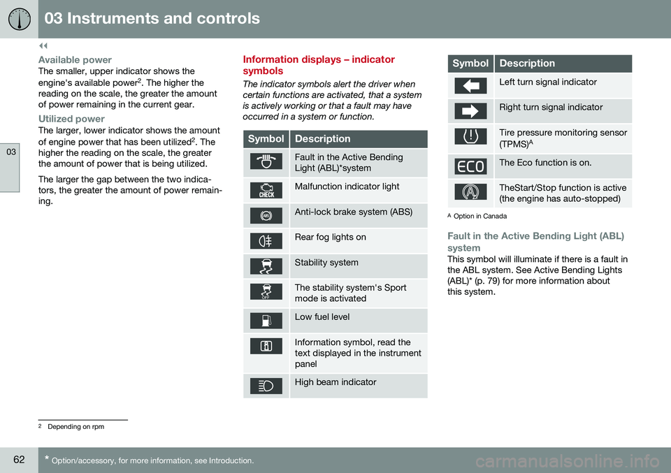
The indicator symbols alert the driver when certain functions are activated, that a systemis actively working or that a fault may haveoccurred in a system or function.
SymbolDescription
Fault in the Active Bending Light (ABL)*system
Malfunction indicator light
Anti-lock brake system (ABS)
Rear fog lights on
Stability system
The stability system's Sport mode is activated
Low fuel level
Information symbol, read the text displayed in the instrumentpanel
High beam indicator
SymbolDescription
Left turn signal indicator
Right turn signal indicator
Tire pressure monitoring sensor (TPMS) A
The Eco function is on.
TheStart/Stop function is active (the engine has auto-stopped)
A
Option in Canada
Fault in the Active Bending Light (ABL)
system
This symbol will illuminate if there is a fault in the ABL system. See Active Bending Lights(ABL)* (p. 79) for more information aboutthis system.
2 Depending on rpm
Page 65 of 344
03 Instruments and controls
03
}}
* Option/accessory, for more information, see Introduction.63
Malfunction Indicator LightAs you drive, a computer called On-Board Diagnostics II (OBDII) monitors your vehicle'sengine, transmission, electrical and emissionsystems. The malfunction indicator light will illuminate if the computer senses a condition that poten-tially may need correcting. When this hap-pens, please have your vehicle checked by atrained and qualified Volvo service technicianas soon as possible. A malfunction indicator light may have many causes. Sometimes, you may not notice achange in your car's behavior. Even so, anuncorrected condition could hurt fuel econ-omy, emission controls, and drivability.Extended driving without correcting the causecould even damage other components inyour vehicle. This light may illuminate if the fuel filler cap is not closed tightly or if the engine was runningwhile the vehicle was refueled.
Anti-lock Brake System (ABS)If the warning light comes on, there may be a malfunction in the ABS system (the standardbraking system will still function). Check thesystem by:
1. Stopping in a safe place and switching off
the ignition.
2. Restart the engine. 3. If the warning light goes off, no further
action is required.
If the indicator light remains on, the vehicle should be driven to a trained and qualifiedVolvo service technician for inspection, seeBrakes – general (p. 228) for additional infor-mation.
Rear fog lightsThis symbol indicates that the rear fog lights are on.
Stability systemThis indicator symbol flashes when the stabil- ity system is actively working to stabilize thevehicle, see Stability system – introduction(p. 141) for more detailed information.
Stability system - Sport modeThis symbol illuminates to indicate that the stability system's Sport mode has been acti-
vated to help provide maximum tractive force,for example when driving with snow chains,or driving in deep snow or loose sand.
Low fuel levelWhen this light comes on, the vehicle should be refueled as soon as possible. See Refuel-ing – fuel requirements (p. 239) for informa-tion about fuel and refueling.
Information symbolThe information symbol lights up and a text message is displayed to provide the driverwith necessary information about one of thevehicle's systems. The message can beerased and the symbol can be turned off by pressing the
OK button (see Information dis-
play – menu controls (p. 96) for information)or this will take place automatically after ashort time (the length of time varies, depend-ing on the function affected). The information symbol may also illuminate together with other symbols.
High beam indicatorThis symbol illuminates when the high beam headlights are on, or if the high beam flashfunction is used.
Left turn signal indicator
Right turn signal indicator
NOTE
• Both turn signal indicators will flash when the hazard warning flashers areused.
• If either of these indicators flash fasterthan normal, the direction indicatorsare not functioning properly.
Tire pressure monitoring system (TPMS)*
This symbol illuminates to indicate that tire pressure in one or more tires is low, see TirePressure Monitoring System (TPMS) – generalinformation (p. 266) for detailed information.
Eco* function onThe symbol will illuminate when the Eco func- tion is activated.
Page 72 of 344
||
03 Instruments and controls
03
70* Option/accessory, for more information, see Introduction.
Ignition mode II–With the remote key fully pressed into the ignition slot 8
, press START/STOP
ENGINE for approximately 2 seconds.
Returning to mode 0To return to mode 0 from mode II or I, press
START/STOP ENGINE briefly.
Starting and stopping the engineSee Starting the engine (p. 211) and Switch- ing off the engine (p. 213) for information onstarting the engine and switching it off.
Emergency towingSee Towing the vehicle (p. 245) for importantinformation about the remote key when thevehicle is being towed.
Related information
•Inserting/removing remote key (p. 68)
Front seats
The front seats can be adjusted in a number of ways to help provide the most comfortableseating position.
WARNING
•Do not adjust the seat while driving. The seat should be adjusted so thatthe brake pedal can be depressedfully. In addition, position the seat asfar rearward as comfort and controlallow.
• Check that the seat is securely lockedinto position after adjusting.
Related information
•
Front seats – power seat (p. 71)
• Rear seats – folding backrest (p. 74)
• Rear seats – head restraints (p. 74)
Front seats – folding backrest*
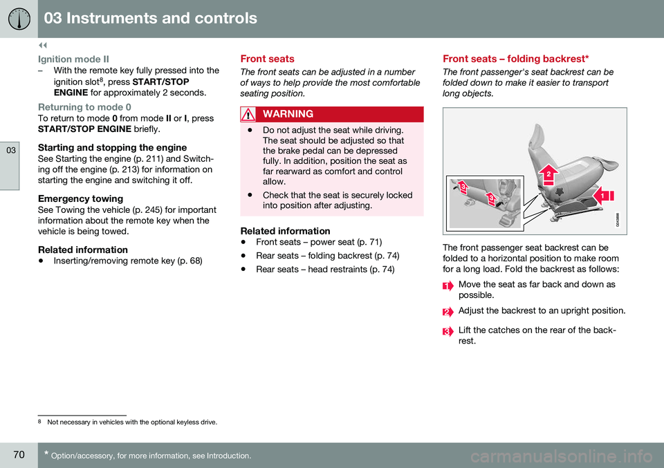
The front passenger's seat backrest can be folded down to make it easier to transportlong objects.
The front passenger seat backrest can be folded to a horizontal position to make roomfor a long load. Fold the backrest as follows:
Move the seat as far back and down as possible.
Adjust the backrest to an upright position.
Lift the catches on the rear of the back- rest.
8
Not necessary in vehicles with the optional keyless drive.
Page 73 of 344
03 Instruments and controls
03
}}
* Option/accessory, for more information, see Introduction.71
Without releasing the catches, push the backrest forward. Move the seat as far forward as possible so that the head restraint slides under theglove compartment.
Return the seat to its upright position in thereverse order.
WARNING
• When transporting long objects, cover sharp edges on the load to help pre-vent injury to occupants. Secure theload to help prevent shifting duringsudden stops.
• When the seat's backrest is returnedto the upright position, push and pull itto be sure that it is securely locked inthis position.
Related information
•
Front seats (p. 70)
• Front seats – power seat (p. 71)
• Rear seats – folding backrest (p. 74)
• Rear seats – head restraints (p. 74)
Front seats – power seat 11
The power seat(s) can be adjusted for a short period after unlocking the door with theremote control without the key in the ignitionslot. Seat adjustment is normally made whenthe ignition is on and can always be madewhen the engine is running.
Power seat
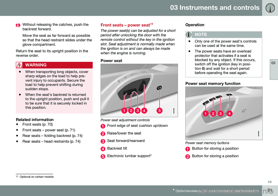
Power seat adjustment controls
Front edge of seat cushion up/down
Raise/lower the seat
Seat forward/rearward
Backrest tilt
Electronic lumbar support*
Operation
NOTE
•
Only one of the power seat's controls can be used at the same time.
• The power seats have an overloadprotector that activates if a seat isblocked by any object. If this occurs,switch off the ignition (key in posi-tion
0) and wait for a short period
before operating the seat again.
Power seat memory function
Power seat memory buttons
Button for storing a position
Button for storing a position
11 Optional on certain models
Page 143 of 344
07 Driver support
07
}}
* Option/accessory, for more information, see Introduction.141
Active chassis* (Four C)
Active chassis, Four-C (Continuously Controlled Chassis Concept), regulates thecharacteristics of the shock absorbers so thatthe vehicle's driving characteristics can beadjusted. There are three settings: Comfort,Sport and Advanced.
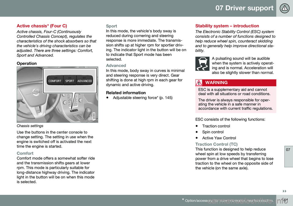
Operation
Chassis settings
Use the buttons in the center console to change setting. The setting in use when theengine is switched off is activated the nexttime the engine is started.
ComfortComfort mode offers a somewhat softer ride and the transmission shifts gears at lowerrpm. This mode is particularly suitable forlong-distance highway driving. The indicatorlight in the button will be on when this modeis selected.
SportIn this mode, the vehicle's body sway is reduced during cornering and steeringresponse is more immediate. The transmis-sion shifts up at higher rpm for sportier driv-ing. The indicator light in the button will be onto indicate that Sport mode has beenselected.
AdvancedIn this mode, body sway in curves is minimal and steering response is very direct. Gearshifting is done at high rpm in each gear fordynamic and active driving.
Related information
• Adjustable steering force* (p. 145)
Stability system – introduction
The Electronic Stability Control (ESC) system consists of a number of functions designed tohelp reduce wheel spin, counteract skiddingand to generally help improve directional sta-bility.
A pulsating sound will be audiblewhen the system is actively operat-ing and is normal. Acceleration willalso be slightly slower than normal.
WARNING
ESC is a supplementary aid and cannot deal with all situations or road conditions. The driver is always responsible for oper- ating the vehicle in a safe manner inaccordance with current traffic regulations.
ESC consists of the following functions:
• Traction control
• Spin control
• Active Yaw Control
Traction Control (TC)This function is designed to help reduce wheel spin at low speeds by transferringpower from a drive wheel that begins to losetraction to the wheel on the opposite side ofthe vehicle (on the same axle).
Page 144 of 344
||
07 Driver support
07
142
Spin Control (SC)The SC function is designed to help prevent the drive wheels from spinning while the vehi-cle is accelerating.
Active Yaw Control (AYC)This function helps maintain directional stabil- ity, for example when cornering, by brakingone or more of the wheels if the vehicleshows a tendency to skid or slide laterally.
Trailer Stability Assist (TSA)The TSA helps stabilize a vehicle that is tow- ing a trailer when the vehicle and trailer havebegun to sway. See Trailer Stability Assist(TSA) (p. 245) for more information. This system is automatically deactivated if the driver selects Sport mode.
Related information
•Stability system – operation (p. 142)
• Stability system – symbols and messages (p. 143)
• Trailer Stability Assist (TSA) (p. 245)
Stability system – operation
Operation
Sport modeThe stability system is always activated and cannot be switched off.
However, the driver canselect Sport mode, which
offers more active drivingcharacteristics. Sport mode can be selected
in the MY CAR menus, see
My Car – introduction (p. 66).
In Sport mode, the engine management sys-
tem monitors movement of the accelerator pedal and steering wheel for sportier drivingby allowing more lateral movement of the rearwheels before ESC is activated. Under certain circumstances, such as when driving with snow chains, or driving in deepsnow or loose sand, it may be advisable totemporarily use Sport mode for maximum
tractive force. If the driver releases pressure on the acceler- ator pedal, ETC will also activate to help sta-bilize the vehicle. To switch to Sport mode:
Sport mode remains active until the driver
switches it off in the menu or until the engine is switched off. ETC will return to normalmode when the engine is restarted.
Related information
• Stability system – introduction (p. 141)
• Stability system – symbols and messages (p. 143)
Page 146 of 344
||
07 Driver support
07
144
SymbolMessageDescription
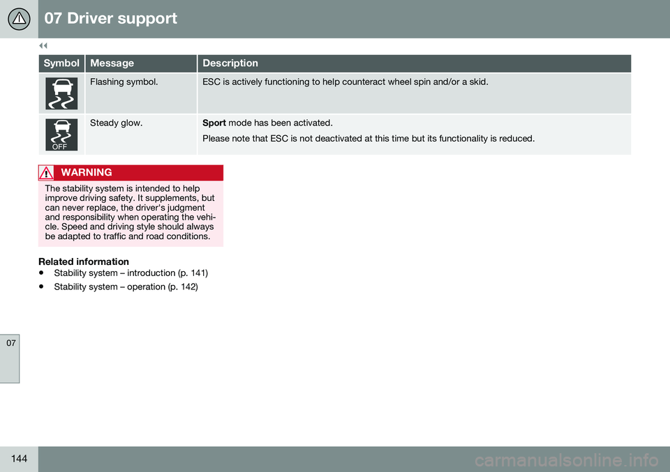
Flashing symbol.ESC is actively functioning to help counteract wheel spin and/or a skid.
Steady glow.Sport mode has been activated.
Please note that ESC is not deactivated at this time but its functionality is reduced.
WARNING
The stability system is intended to help improve driving safety. It supplements, butcan never replace, the driver's judgmentand responsibility when operating the vehi-cle. Speed and driving style should alwaysbe adapted to traffic and road conditions.
Related information
• Stability system – introduction (p. 141)
• Stability system – operation (p. 142)
Page 160 of 344
||
07 Driver support
07
158
The driver will then have to reactivate ACC in one of the following ways:• By pressing
•By accelerating up to at least 3 mph (4 km/h). ACC will then resume followingthe vehicle ahead.
Your vehicle will then resume following the vehicle ahead at the set time interval.
NOTE
ACC can remain active and keep your vehicle at a standstill for up to 4 minutes.After 4 minutes have elapsed, the parkingbrake will be engaged and ACC will go intostandby mode. To reactivate ACC, the driver must release the parking brake (see Parking brake –general information (p. 232)).
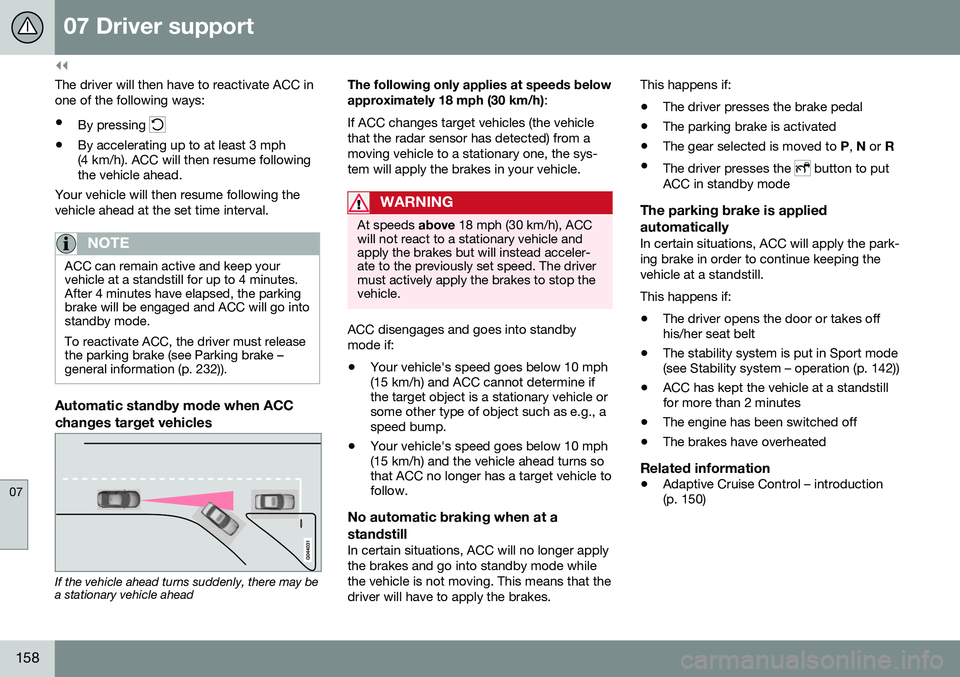
Automatic standby mode when ACC changes target vehicles
If the vehicle ahead turns suddenly, there may be a stationary vehicle ahead The following only applies at speeds below approximately 18 mph (30 km/h)
:
If ACC changes target vehicles (the vehicle that the radar sensor has detected) from amoving vehicle to a stationary one, the sys-tem will apply the brakes in your vehicle.
WARNING
At speeds above 18 mph (30 km/h), ACC
will not react to a stationary vehicle and apply the brakes but will instead acceler-ate to the previously set speed. The drivermust actively apply the brakes to stop thevehicle.
ACC disengages and goes into standby mode if:
• Your vehicle's speed goes below 10 mph (15 km/h) and ACC cannot determine ifthe target object is a stationary vehicle orsome other type of object such as e.g., aspeed bump.
• Your vehicle's speed goes below 10 mph(15 km/h) and the vehicle ahead turns sothat ACC no longer has a target vehicle tofollow.
No automatic braking when at a standstill
In certain situations, ACC will no longer apply the brakes and go into standby mode whilethe vehicle is not moving. This means that thedriver will have to apply the brakes. This happens if:
• The driver presses the brake pedal
• The parking brake is activated
• The gear selected is moved to
P, N or R
• The driver presses the
button to put
ACC in standby mode
The parking brake is applied automatically
In certain situations, ACC will apply the park- ing brake in order to continue keeping thevehicle at a standstill. This happens if:
• The driver opens the door or takes off his/her seat belt
• The stability system is put in Sport mode(see Stability system – operation (p. 142))
• ACC has kept the vehicle at a standstillfor more than 2 minutes
• The engine has been switched off
• The brakes have overheated
Related information
•
Adaptive Cruise Control – introduction(p. 150)
Page 219 of 344
08 Starting and driving
08
217
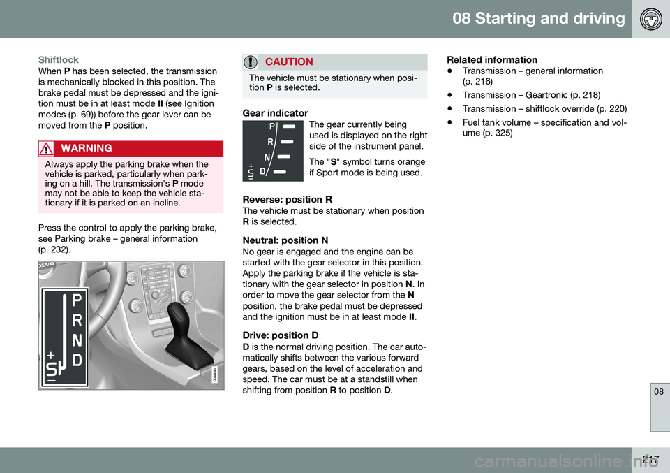
ShiftlockWhen P has been selected, the transmission
is mechanically blocked in this position. The brake pedal must be depressed and the igni-tion must be in at least mode II (see Ignition
modes (p. 69)) before the gear lever can bemoved from the P position.
WARNING
Always apply the parking brake when the vehicle is parked, particularly when park-ing on a hill. The transmission's P mode
may not be able to keep the vehicle sta-tionary if it is parked on an incline.
Press the control to apply the parking brake, see Parking brake – general information(p. 232).
CAUTION
The vehicle must be stationary when posi- tion P is selected.
Gear indicatorThe gear currently being used is displayed on the rightside of the instrument panel. The " S" symbol turns orange
if Sport mode is being used.
Reverse: position RThe vehicle must be stationary when position R is selected.
Neutral: position NNo gear is engaged and the engine can bestarted with the gear selector in this position.Apply the parking brake if the vehicle is sta-tionary with the gear selector in position N. In
order to move the gear selector from the N
position, the brake pedal must be depressedand the ignition must be in at least mode II.
Drive: position DD is the normal driving position. The car auto-
matically shifts between the various forwardgears, based on the level of acceleration andspeed. The car must be at a standstill whenshifting from position R to position D.
Related information
• Transmission – general information (p. 216)
• Transmission – Geartronic (p. 218)
• Transmission – shiftlock override (p. 220)
• Fuel tank volume – specification and vol-ume (p. 325)