ECU VOLVO S60 INSCRIPTION 2017 Owner´s Manual
[x] Cancel search | Manufacturer: VOLVO, Model Year: 2017, Model line: S60 INSCRIPTION, Model: VOLVO S60 INSCRIPTION 2017Pages: 398, PDF Size: 9.45 MB
Page 251 of 398
DRIVER SUPPORT
* Option/accessory, for more information, see Introduction.249
The BLIS/CTA
16
sensors are located on the
inside of the rear fenders/bumper. The surfaces in front of the sensors must be kept clean for the system to function optimally.
CAUTION
Repairs to the BLIS/CTA systems and/or repainting the rear bumper should only bedone by a trained and qualified Volvo servicetechnician.
Related information
• BLIS
* – introduction (p. 244)
• BLIS
* – function (p. 245)
• BLIS
* – operation (p. 246)
• BLIS
* – Cross Traffic Alert (CTA) (p. 247)
• BLIS
* – messages (p. 249)
BLIS * – messages
If BLIS/CTA 17
are not functioning normally, a
symbol will illuminate in the instrument panel and a text message will be displayed. Follow anyinstructions that may be provided. These messages include:
MessageSystem status
CTA OFFCTA has been switched off manually. BLIS remains active.
BLIS and CTA OFFTrailerattachedBLIS and CTA are temporarily deactivated because a trailer'swiring has been connected tothe vehicle's electrical system.
BLIS and CTA ServicerequiredBLIS and CTA are not func- tioning normally.
• If this message recurs,the systems should beinspected by a trainedand qualified Volvo serv-ice technician.
Messages can be erased by pressing the
OK
button on the left steering wheel lever.
Related information
• BLIS
* – introduction (p. 244)
• BLIS
* – function (p. 245)
• BLIS
* – operation (p. 246)
• BLIS
* – Cross Traffic Alert (CTA) (p. 247)
• BLIS
* – limitations (p. 248)
16
Cross Traffic Alert
17 Cross Traffic Alert
Page 254 of 398
STARTING AND DRIVING
* Option/accessory, for more information, see Introduction.
252
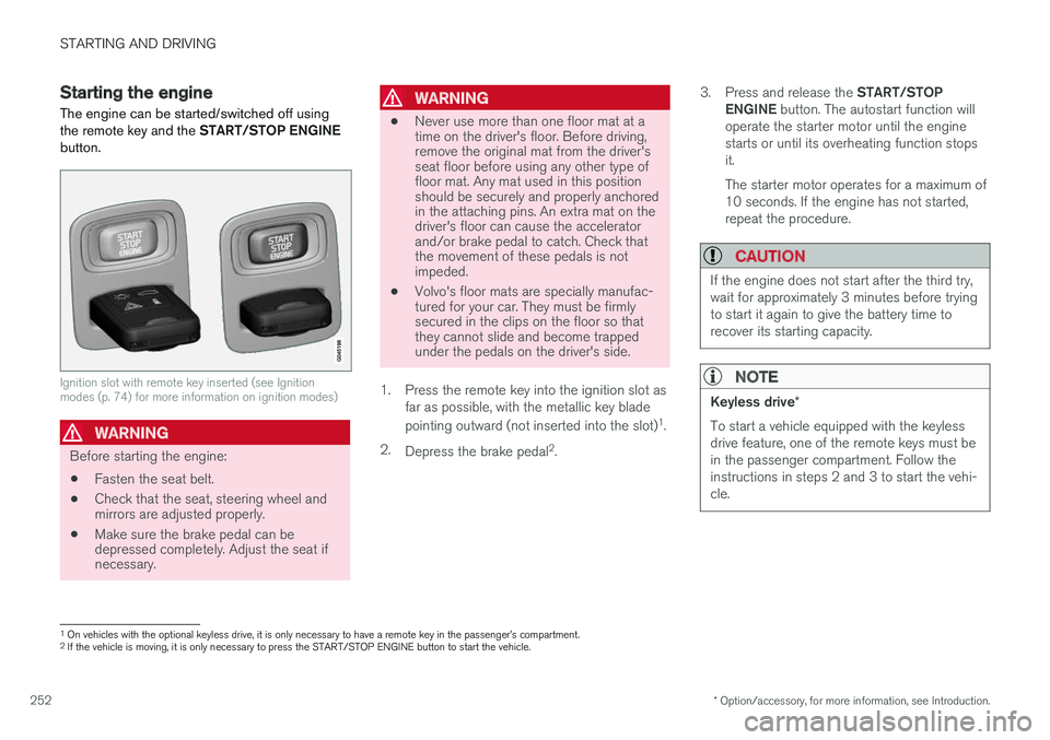
Starting the engine
The engine can be started/switched off using the remote key and the START/STOP ENGINE
button.
Ignition slot with remote key inserted (see Ignition modes (p. 74) for more information on ignition modes)
WARNING
Before starting the engine:
• Fasten the seat belt.
• Check that the seat, steering wheel and mirrors are adjusted properly.
• Make sure the brake pedal can bedepressed completely. Adjust the seat ifnecessary.
WARNING
•Never use more than one floor mat at a time on the driver's floor. Before driving,remove the original mat from the driver'sseat floor before using any other type offloor mat. Any mat used in this positionshould be securely and properly anchoredin the attaching pins. An extra mat on thedriver's floor can cause the acceleratorand/or brake pedal to catch. Check thatthe movement of these pedals is notimpeded.
• Volvo's floor mats are specially manufac-tured for your car. They must be firmlysecured in the clips on the floor so thatthey cannot slide and become trappedunder the pedals on the driver's side.
1. Press the remote key into the ignition slot as far as possible, with the metallic key blade pointing outward (not inserted into the slot) 1
.
2. Depress the brake pedal 2
. 3.
Press and release the START/STOP
ENGINE button. The autostart function will
operate the starter motor until the engine starts or until its overheating function stopsit. The starter motor operates for a maximum of 10 seconds. If the engine has not started,repeat the procedure.
CAUTION
If the engine does not start after the third try, wait for approximately 3 minutes before tryingto start it again to give the battery time torecover its starting capacity.
NOTE
Keyless drive *
To start a vehicle equipped with the keyless drive feature, one of the remote keys must bein the passenger compartment. Follow theinstructions in steps 2 and 3 to start the vehi-cle.
1 On vehicles with the optional keyless drive, it is only necessary to have a remote key in the passenger
Page 275 of 398
STARTING AND DRIVING
}}
273
Parking brake – general information The electric parking brake helps to keep the vehicle stationary when it is parked.
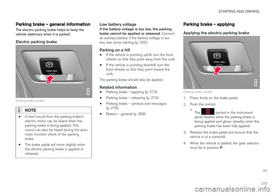
Electric parking brake
Parking brake control
NOTE
•A faint sound from the parking brake's electric motor can be heard when theparking brake is being applied. Thissound can also be heard during the auto-matic function check of the parkingbrake.
• The brake pedal will move slightly whenthe electric parking brake is applied orreleased.
Low battery voltageIf the battery voltage is too low, the parking brake cannot be applied or released.
Connect
an auxiliary battery if the battery voltage is toolow, see Jump starting (p. 255).
Parking on a hill
• If the vehicle is pointing uphill, turn the frontwheels so that they point away from the curb.
• If the vehicle is pointing downhill, turn thefront wheels so that they point toward thecurb.
The parking brake should also be applied.
Related information
• Parking brake – applying (p. 273)
• Parking brake – releasing (p. 274)
• Parking brake – symbols and messages(p. 276)
• Brakes – general (p. 269)
Parking brake – applying
Applying the electric parking brake
Parking brake control
1. Press firmly on the brake pedal. 2.Push the control. >
The
symbol in the instrument
panel flashes while the parking brake is being applied and glows steadily when theparking brake has been fully applied.
3. Release the brake pedal and ensure that the vehicle is at a standstill.
4. When the vehicle is parked, the gear selector must be in position P.
Page 290 of 398
STARTING AND DRIVING
288
Towing the vehicle Always check with state and local authorities before attempting to tow another vehiclebecause this type of towing is subject to regula-tions regarding maximum towing speed, lengthand type of towing device, lighting, etc.
1. With the remote key fully pressed into theignition slot 14
, press START/STOP ENGINE
for approximately 2 seconds to activate igni- tion mode II.
2. The remote key must remain in the ignition slot15
for the entire time that the vehicle is
being towed.
3. Keep the tow rope taut when the towing vehicle slows down by applying light pressure on the brake pedal. This will help prevent jar-ring movements of the vehicle being towed.
4. Be prepared to apply the brakes to stop the vehicle being towed.
CAUTION
General towing precautions:
• Please check with state and local author- ities before attempting this type of tow-ing, as vehicles being towed are subjectto regulations regarding maximum towingspeed, length and type of towing device,lighting, etc.
• If the vehicle's battery is dead, see Jumpstarting (p. 255) to provide current forreleasing the electric parking brake and to move the gear selector from the
P
position to N. If this is not possible, see
Transmission – shiftlock override (p. 261) for information about manually overridingthe shiftlock system to move the gear selector from P to N.
• Maximum speed: 50 mph (80 km/h). Do not exceed the maximum allowable tow-ing speed.
• Maximum distance with front wheels onground: 50 miles (80 km).
• The vehicle should only be towed in theforward direction.
Related information
• Towing eyelet (p. 288)
• Remote key – functions (p. 147)
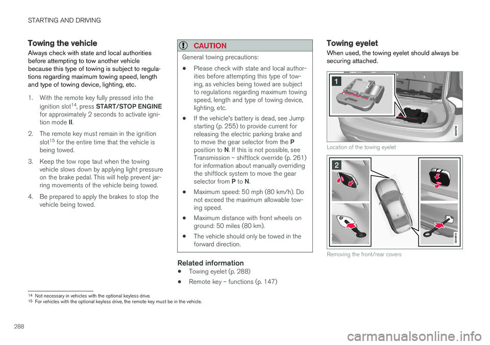
Towing eyelet
When used, the towing eyelet should always be securing attached.
Location of the towing eyelet
Removing the front/rear covers
14 Not necessary in vehicles with the optional keyless drive.
15 For vehicles with the optional keyless drive, the remote key must be in the vehicle.
Page 291 of 398
STARTING AND DRIVING
}}
289
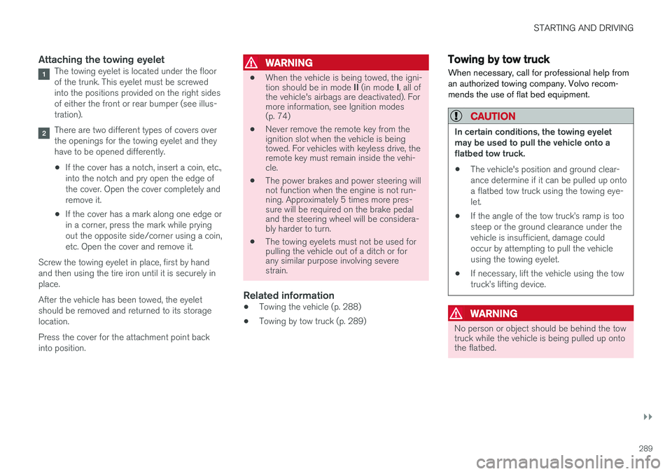
Attaching the towing eyeletThe towing eyelet is located under the floor of the trunk. This eyelet must be screwedinto the positions provided on the right sidesof either the front or rear bumper (see illus-tration).
There are two different types of covers over the openings for the towing eyelet and theyhave to be opened differently.
• If the cover has a notch, insert a coin, etc.,into the notch and pry open the edge ofthe cover. Open the cover completely andremove it.
• If the cover has a mark along one edge orin a corner, press the mark while pryingout the opposite side/corner using a coin,etc. Open the cover and remove it.
Screw the towing eyelet in place, first by handand then using the tire iron until it is securely inplace. After the vehicle has been towed, the eyelet should be removed and returned to its storagelocation. Press the cover for the attachment point back into position.
WARNING
• When the vehicle is being towed, the igni- tion should be in mode
II (in mode I, all of
the vehicle's airbags are deactivated). For more information, see Ignition modes(p. 74)
• Never remove the remote key from theignition slot when the vehicle is beingtowed. For vehicles with keyless drive, theremote key must remain inside the vehi-cle.
• The power brakes and power steering willnot function when the engine is not run-ning. Approximately 5 times more pres-sure will be required on the brake pedaland the steering wheel will be considera-bly harder to turn.
• The towing eyelets must not be used forpulling the vehicle out of a ditch or forany similar purpose involving severestrain.
Related information
•Towing the vehicle (p. 288)
• Towing by tow truck (p. 289)
Towing by tow truck
When necessary, call for professional help from an authorized towing company. Volvo recom-mends the use of flat bed equipment.
CAUTION
In certain conditions, the towing eyelet may be used to pull the vehicle onto aflatbed tow truck.
• The vehicle's position and ground clear-ance determine if it can be pulled up ontoa flatbed tow truck using the towing eye-let.
• If the angle of the tow truck
Page 300 of 398
WHEELS AND TIRES
* Option/accessory, for more information, see Introduction.
298
Changing a wheel – spare wheel Wheel changes should always be carried out correctly.
Spare tireA spare tire can be purchased for your vehicle as an accessory. Follow the instructions includedwith the spare tire regarding use and stowing inthe vehicle. See also Changing a wheel – remov-ing wheel (p. 295) for additional information.
Spare wheelThe following instructions only apply if you have purchased a temporary spare wheel * for your
vehicle. If there is no temporary spare wheel in your vehi- cle, please see Tire sealing system * – general
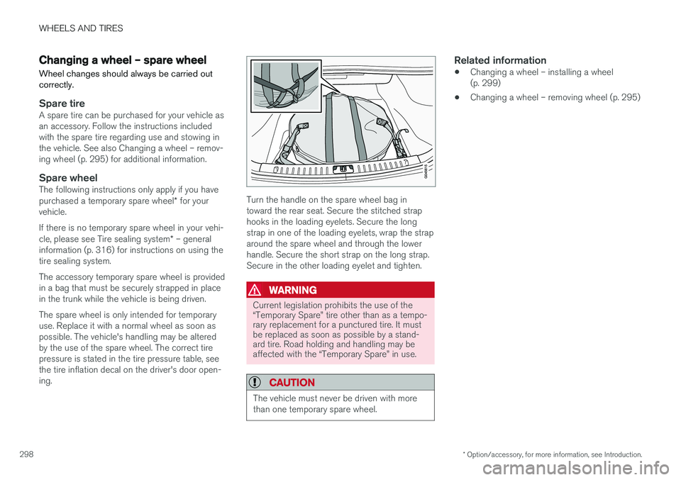
information (p. 316) for instructions on using the tire sealing system. The accessory temporary spare wheel is provided in a bag that must be securely strapped in placein the trunk while the vehicle is being driven. The spare wheel is only intended for temporary use. Replace it with a normal wheel as soon aspossible. The vehicle's handling may be alteredby the use of the spare wheel. The correct tirepressure is stated in the tire pressure table, seethe tire inflation decal on the driver's door open-ing.Turn the handle on the spare wheel bag in toward the rear seat. Secure the stitched straphooks in the loading eyelets. Secure the longstrap in one of the loading eyelets, wrap the straparound the spare wheel and through the lowerhandle. Secure the short strap on the long strap.Secure in the other loading eyelet and tighten.
WARNING
Current legislation prohibits the use of the “Temporary Spare” tire other than as a tempo-rary replacement for a punctured tire. It mustbe replaced as soon as possible by a stand-ard tire. Road holding and handling may beaffected with the “Temporary Spare” in use.
CAUTION
The vehicle must never be driven with more than one temporary spare wheel.
Related information
• Changing a wheel – installing a wheel (p. 299)
• Changing a wheel – removing wheel (p. 295)
Page 301 of 398
WHEELS AND TIRES
}}
* Option/accessory, for more information, see Introduction.299
Changing a wheel – accessing the spare wheel
The following procedure explains how to access the spare wheel (where applicable).
1. Release the bag's retaining straps.
2. Lift the bag out of the vehicle and remove the spare wheel from the bag.
3. Fold up the floor hatch in the trunk.4. Remove the jack * and tools * from the foam
block and change the wheels (see the instructions in the following section "Chang-ing a wheel").
5. After changing wheels, return the jack and tools to the foam block and close the floorhatch.
6. If possible, place the wheel with the punc- tured tire in the bag. 7. If there is a wheel in the bag, strap the bag
securely in place in the trunk.
WARNING
•If there is a wheel in the bag, the bag must be securely restrained using its straps andthe load anchoring eyelets in the trunk.See (p. 298) and carefully follow theinstructions.
• If the wheel with the punctured tire is toobig to fit in the bag, it should be securelyrestrained in the trunk using suitablestraps, a net for anchoring cargo, etc.
Changing a wheel – installing a wheel
It is important to re-install wheels properly.
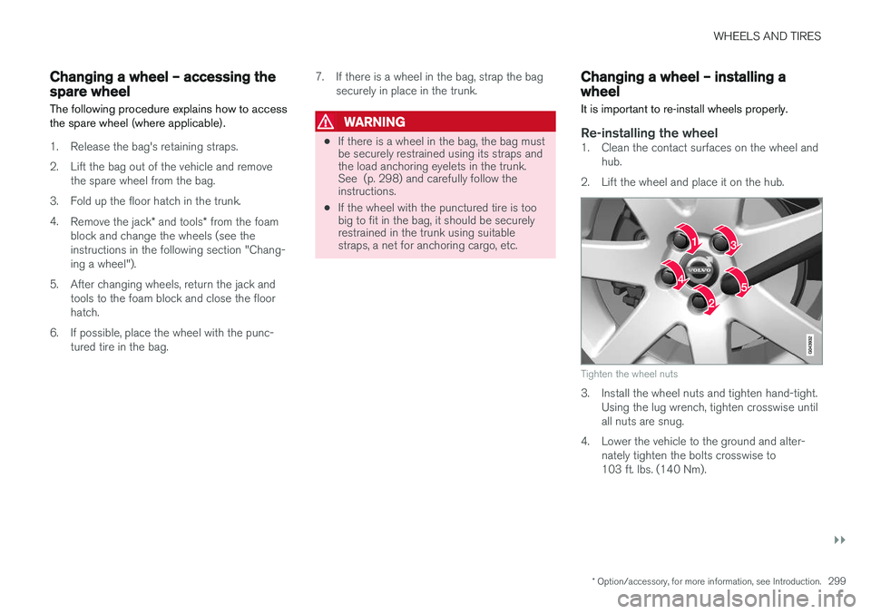
Re-installing the wheel1. Clean the contact surfaces on the wheel and hub.
2. Lift the wheel and place it on the hub.
Tighten the wheel nuts
3. Install the wheel nuts and tighten hand-tight. Using the lug wrench, tighten crosswise until all nuts are snug.
4. Lower the vehicle to the ground and alter- nately tighten the bolts crosswise to103 ft. lbs. (140 Nm).
Page 321 of 398
WHEELS AND TIRES
}}
* Option/accessory, for more information, see Introduction.319
Tire sealing system* – sealing a
hole The tire sealing system can be used to tempo- rarily seal a hole in the tread surface of a tire.
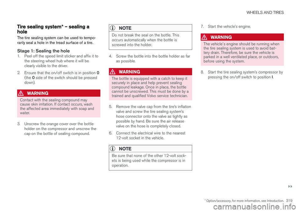
Stage 1: Sealing the hole1. Peel off the speed limit sticker and affix it to the steering wheel hub where it will be clearly visible to the driver.
2. Ensure that the on/off switch is in position 0
(the 0 side of the switch should be pressed
down).
WARNING
Contact with the sealing compound may cause skin irritation. If contact occurs, washthe affected area immediately with soap andwater.
3. Unscrew the orange cover over the bottle holder on the compressor and unscrew the cap on the bottle of sealing compound.
NOTE
Do not break the seal on the bottle. This occurs automatically when the bottle isscrewed into the holder.
4. Screw the bottle into the bottle holder as faras possible.
WARNING
The bottle is equipped with a catch to keep it securely in place and help prevent sealingcompound leakage. Once in place, the bottlecannot be unscrewed. This must be done by atrained and qualified Volvo service technician.
5. Remove the valve cap from the tire
Page 341 of 398
MAINTENANCE AND SERVICING
339
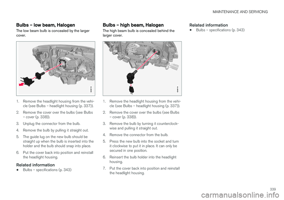
Bulbs – low beam, Halogen The low beam bulb is concealed by the larger cover.
1. Remove the headlight housing from the vehi-cle (see Bulbs – headlight housing (p. 337)).
2. Remove the cover over the bulbs (see Bulbs – cover (p. 338)).
3. Unplug the connector from the bulb.
4. Remove the bulb by pulling it straight out.
5. The guide lug on the new bulb should be straight up when the bulb is inserted into the holder and the bulb should snap into place.
6. Put the cover back into position and reinstall the headlight housing.
Related information
• Bulbs – specifications (p. 343)
Bulbs – high beam, Halogen
The high beam bulb is concealed behind the larger cover.
1. Remove the headlight housing from the vehi- cle (see Bulbs – headlight housing (p. 337)).
2. Remove the cover over the bulbs (see Bulbs – cover (p. 338)).
3. Remove the bulb by turning it counterclock- wise and pulling it straight out.
4. Remove the connector from the bulb.
5. Press the new bulb into the socket and turn it clockwise to put it in place. It can only be secured in one position.
6. Reinsert the bulb holder into the headlight housing.
7. Put the cover back into position and reinstall the headlight housing.
Related information
• Bulbs – specifications (p. 343)
Page 342 of 398
MAINTENANCE AND SERVICING
340
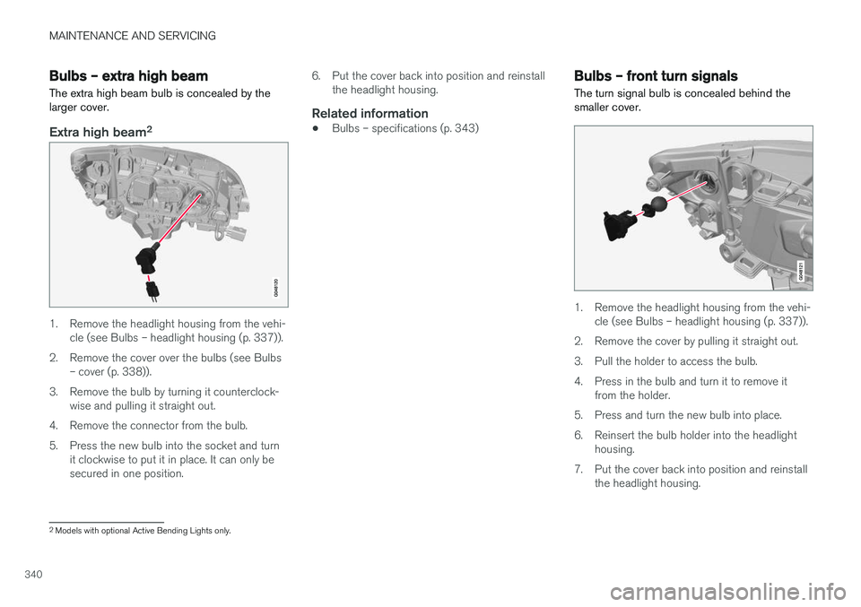
Bulbs – extra high beam The extra high beam bulb is concealed by the larger cover.
Extra high beam2
1. Remove the headlight housing from the vehi-
cle (see Bulbs – headlight housing (p. 337)).
2. Remove the cover over the bulbs (see Bulbs – cover (p. 338)).
3. Remove the bulb by turning it counterclock- wise and pulling it straight out.
4. Remove the connector from the bulb.
5. Press the new bulb into the socket and turn it clockwise to put it in place. It can only be secured in one position. 6. Put the cover back into position and reinstall
the headlight housing.
Related information
• Bulbs – specifications (p. 343)
Bulbs – front turn signals The turn signal bulb is concealed behind the smaller cover.
1. Remove the headlight housing from the vehi-
cle (see Bulbs – headlight housing (p. 337)).
2. Remove the cover by pulling it straight out.
3. Pull the holder to access the bulb.
4. Press in the bulb and turn it to remove it from the holder.
5. Press and turn the new bulb into place.
6. Reinsert the bulb holder into the headlight housing.
7. Put the cover back into position and reinstall the headlight housing.
2Models with optional Active Bending Lights only.