AUX VOLVO S80 2016 Owner´s Manual
[x] Cancel search | Manufacturer: VOLVO, Model Year: 2016, Model line: S80, Model: VOLVO S80 2016Pages: 380, PDF Size: 9.45 MB
Page 5 of 380
Contents
* Option/accessory, for more information, see Introduction.3
03
03 Instruments and controls
Instrument overview ................................. 59
Information displays – introduction........... 62
Eco Guide* and Power Meter*.................. 65
Information displays – indicator symbols. 66
Information displays – warning symbols... 68
My Car – introduction............................... 70Information displays – ambient tempera-
ture sensor................................................ 71 Information displays – trip odometer and
clock......................................................... 72
Inserting/removing remote key................. 72
Ignition modes.......................................... 73
Front seats................................................ 74
Front seats – folding backrest*................. 75
Front seats – power seat.......................... 75Key memory – power driver's seat* and
door mirrors.............................................. 77
Rear seats – head restraints..................... 78
Rear seats – folding backrest................... 80
Steering wheel.......................................... 81
Electrically heated* steering wheel........... 82
Lighting panel........................................... 82
High/low beam headlights........................ 83
Active high beams (AHB)*......................... 84
03
Tunnel detection (models with the rain
sensor* only)............................................. 85
Active Bending Lights (ABL)*.................... 85
Auxiliary lights*.......................................... 86
Instrument and "theater" lighting.............. 86
Parking lights............................................ 87
Rear fog lights........................................... 87
Hazard warning flashers........................... 88
Turn signals............................................... 88
Front interior lighting................................. 89
Rear interior lighting.................................. 90
Home safe lighting.................................... 90
Approach lighting...................................... 91
Windshield wipers..................................... 91
Rain sensor*.............................................. 92
Windshield washer.................................... 92
Tailgate wiper/washer............................... 93
Power windows......................................... 94
Sun shades*.............................................. 95
Power door mirrors................................... 96Power door mirrors – automatic tilting/
retraction................................................... 97 Heated windshield*, rear window and
door mirror defrosters............................... 98
03
Interior rearview mirror.............................. 98
Digital compass*....................................... 99
Power moonroof – introduction.............. 100
Power moonroof – operation.................. 101 HomeLink ®
Wireless Control System* –
introduction............................................. 102HomeLink ®
Wireless Control System* –
programming........................................... 103
Volvo Sensus.......................................... 105
Information display – menu controls....... 106
Information display – menu overview..... 107
Information display – messages............. 107
Trip computer – introduction ................. 109Trip computer – functions, analog instru-
ment panel.............................................. 110 Trip computer – functions, digital instru-
ment panel.............................................. 113 Trip computer – Supplementary informa-
tion.......................................................... 115
Trip computer – Trip statistics................ 116
Page 88 of 380
||
03 Instruments and controls
03
86* Option/accessory, for more information, see Introduction.
NOTE
This function is only active in twilight or dark conditions, and only when the vehicleis in motion.
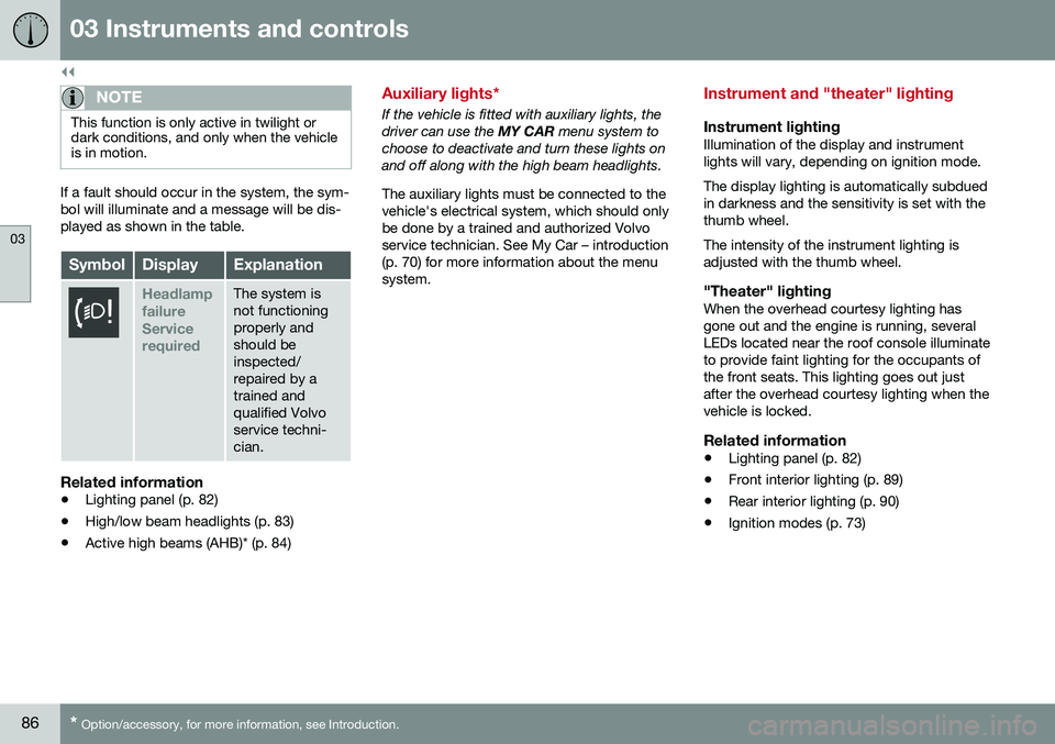
If a fault should occur in the system, the sym- bol will illuminate and a message will be dis-played as shown in the table.
SymbolDisplayExplanation
Headlamp failureServicerequiredThe system is not functioningproperly andshould beinspected/repaired by atrained andqualified Volvoservice techni-cian.
Related information
• Lighting panel (p. 82)
• High/low beam headlights (p. 83)
• Active high beams (AHB)* (p. 84)
Auxiliary lights*
If the vehicle is fitted with auxiliary lights, the driver can use the
MY CAR menu system to
choose to deactivate and turn these lights onand off along with the high beam headlights. The auxiliary lights must be connected to the vehicle's electrical system, which should onlybe done by a trained and authorized Volvoservice technician. See My Car – introduction(p. 70) for more information about the menusystem.
Instrument and "theater" lighting
Instrument lightingIllumination of the display and instrument lights will vary, depending on ignition mode. The display lighting is automatically subdued in darkness and the sensitivity is set with thethumb wheel. The intensity of the instrument lighting is adjusted with the thumb wheel.
"Theater" lightingWhen the overhead courtesy lighting hasgone out and the engine is running, severalLEDs located near the roof console illuminateto provide faint lighting for the occupants ofthe front seats. This lighting goes out justafter the overhead courtesy lighting when thevehicle is locked.
Related information
• Lighting panel (p. 82)
• Front interior lighting (p. 89)
• Rear interior lighting (p. 90)
• Ignition modes (p. 73)
Page 135 of 380
05 Loading and storage
05
* Option/accessory, for more information, see Introduction.133
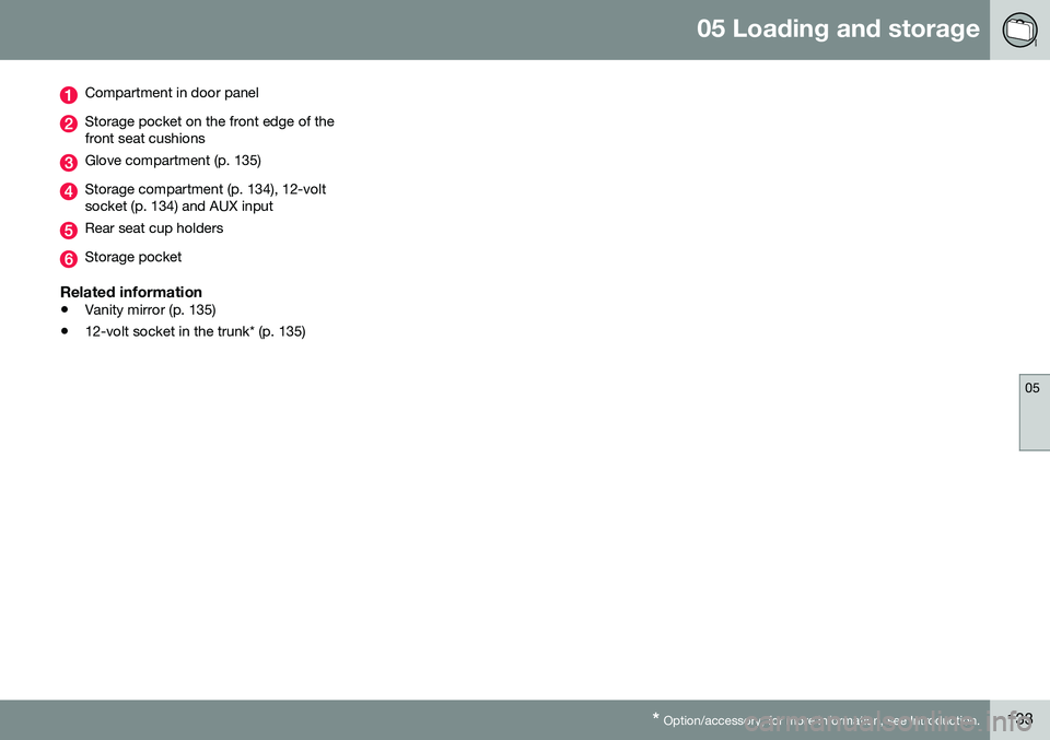
Compartment in door panel
Storage pocket on the front edge of the front seat cushions
Glove compartment (p. 135)
Storage compartment (p. 134), 12-volt socket (p. 134) and AUX input
Rear seat cup holders
Storage pocket
Related information
• Vanity mirror (p. 135)
• 12-volt socket in the trunk* (p. 135)
Page 136 of 380
05 Loading and storage
05
134* Option/accessory, for more information, see Introduction.
Tunnel console
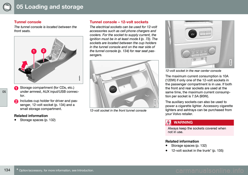
The tunnel console is located between the front seats.
Storage compartment (for CDs, etc.) under armrest, AUX input/USB connec-tor.
Includes cup holder for driver and pas- senger, 12-volt socket (p. 134) and asmall storage compartment.
Related information
• Storage spaces (p. 132)
Tunnel console – 12-volt sockets
The electrical sockets can be used for 12-volt accessories such as cell phone chargers andcoolers. For the socket to supply current, theignition must be in at least mode
I (p. 73). The
sockets are located between the cup holdersin the tunnel console and on the rear side ofthe tunnel console (p. 134) for rear seat pas-sengers.
G021439
12-volt socket in the front tunnel console
G021440
12-volt socket in the rear center console
The maximum current consumption is 10A (120W) if only one of the 12-volt sockets inthe passenger compartment is in use. If boththe front and rear sockets are used at thesame time, the maximum current consump-tion per socket is 7.5A (90W). The auxiliary sockets can also be used to power a cigarette lighter. Accessory cigarettelighters and ashtrays can be purchased fromyour Volvo retailer.
WARNING
Always keep the sockets covered when not in use.
Related information
• Storage spaces (p. 132)
• 12-volt socket in the trunk* (p. 135)
Page 193 of 380
07 Driver support
07
}}
191
City Safety – operation
Using City Safety™
NOTE
The City Safety™ function is activated automatically each time the engine hasbeen switched off and restarted.
On and OffIn certain situations, it may be desirable to switch City Safety™ off, such as when drivingin close quarters where leaves, branches, etc.may obscure the hood and windshield. When the engine is running, City Safety™ can be switched off as follows: Press My Car in the center console control
panel and go to
SettingsCar settings
Driver support systemsCity Safety.
Select
Off.
If the engine is switched off, City Safety™ will reactivate when the engine is restarted.
WARNING
The laser sensor emits light when the igni- tion is in mode II or higher, even if City
Safety™ has been switched off.
To switch City Safety™ on again:
• Follow the same procedure as for switch- ing City Safety™ off but select
On.
Related information
•City Safety – introduction (p. 189)
• City Safety – function (p. 190)
• City Safety – limitations (p. 191)
• City Safety – troubleshooting (p. 192)
• City Safety – symbols and messages (p. 194)
• City Safety – Laser sensor (p. 195)
• My Car – introduction (p. 70)
City Safety – limitations
Limitations
WARNING
The laser sensor has certain limitations and its function may be reduced (or it maynot function at all) in conditions such asheavy rain or snowfall, or by dense fog orthick, blowing dust or snow. Condensa-tion, dirt, ice or snow on the windshieldmay also interfere with the sensor’s func-tion.
The sensor used by City Safety™ is designed to detect cars and other larger motor vehiclesahead of your vehicle in both daylight anddarkness. Objects such as warning flags hanging from long objects on the roof or accessories suchas auxiliary lights or protective arches on thefront of the vehicle that are higher than thehood may also impede the sensor’s function. Braking distance to the vehicle ahead increa- ses on slippery road surfaces, which mayreduce City Safety’s capacity to avoid a colli-sion. In situations like this, the stability sys-tem (see Stability system – introduction(p. 162)) will help provide the best possiblebraking capacity and stability. City Safety™ emits a laser beam and meas- ures the way in which the light is reflected.
Page 223 of 380
07 Driver support
07
}}
221
Front park assist
G021424
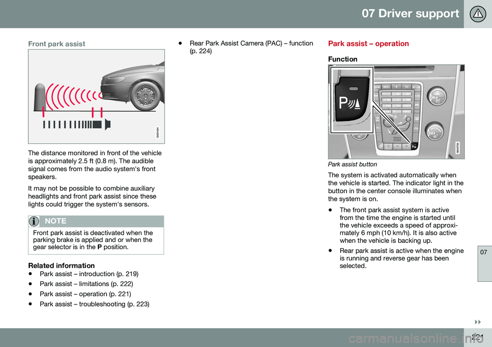
The distance monitored in front of the vehicle is approximately 2.5 ft (0.8 m). The audiblesignal comes from the audio system's frontspeakers. It may not be possible to combine auxiliary headlights and front park assist since theselights could trigger the system's sensors.
NOTE
Front park assist is deactivated when the parking brake is applied and or when thegear selector is in the P position.
Related information
• Park assist – introduction (p. 219)
• Park assist – limitations (p. 222)
• Park assist – operation (p. 221)
• Park assist – troubleshooting (p. 223) •
Rear Park Assist Camera (PAC) – function (p. 224)
Park assist – operation
Function
Park assist button
The system is activated automatically when the vehicle is started. The indicator light in thebutton in the center console illuminates whenthe system is on.
• The front park assist system is active from the time the engine is started untilthe vehicle exceeds a speed of approxi-mately 6 mph (10 km/h). It is also activewhen the vehicle is backing up.
• Rear park assist is active when the engineis running and reverse gear has beenselected.
Page 239 of 380
08 Starting and driving
08
237
Jump starting
Follow these instructions to jump start your vehicle's dead battery or to jump start anothervehicle's dead battery using your vehicle.
G021347
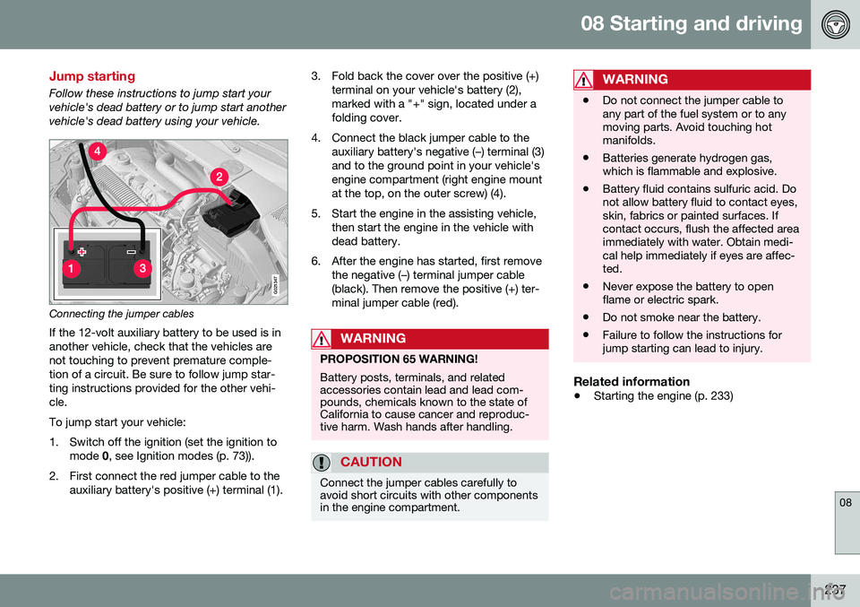
Connecting the jumper cablesIf the 12-volt auxiliary battery to be used is in another vehicle, check that the vehicles arenot touching to prevent premature comple-tion of a circuit. Be sure to follow jump star-ting instructions provided for the other vehi-cle. To jump start your vehicle:
1. Switch off the ignition (set the ignition to mode 0, see Ignition modes (p. 73)).
2. First connect the red jumper cable to the auxiliary battery's positive (+) terminal (1). 3. Fold back the cover over the positive (+)
terminal on your vehicle's battery (2), marked with a "+" sign, located under afolding cover.
4. Connect the black jumper cable to the auxiliary battery's negative (–) terminal (3)and to the ground point in your vehicle'sengine compartment (right engine mountat the top, on the outer screw) (4).
5. Start the engine in the assisting vehicle, then start the engine in the vehicle withdead battery.
6. After the engine has started, first remove the negative (–) terminal jumper cable(black). Then remove the positive (+) ter-minal jumper cable (red).
WARNING
PROPOSITION 65 WARNING! Battery posts, terminals, and related accessories contain lead and lead com-pounds, chemicals known to the state ofCalifornia to cause cancer and reproduc-tive harm. Wash hands after handling.
CAUTION
Connect the jumper cables carefully to avoid short circuits with other componentsin the engine compartment.
WARNING
•Do not connect the jumper cable to any part of the fuel system or to anymoving parts. Avoid touching hotmanifolds.
• Batteries generate hydrogen gas,which is flammable and explosive.
• Battery fluid contains sulfuric acid. Donot allow battery fluid to contact eyes,skin, fabrics or painted surfaces. Ifcontact occurs, flush the affected areaimmediately with water. Obtain medi-cal help immediately if eyes are affec-ted.
• Never expose the battery to openflame or electric spark.
• Do not smoke near the battery.
• Failure to follow the instructions forjump starting can lead to injury.
Related information
•
Starting the engine (p. 233)
Page 244 of 380
||
08 Starting and driving
08
242
Geartronic: starting on slippery
surfaces
Selecting 3rd gear in Geartronic’s manual shifting mode can help provide better tractionwhen starting off on slippery surfaces. To doso:
1. Depress the brake pedal and move the gear selector to the side from D toward
+S– .
2. Press the gear selector forward and release it (this selects 2nd gear). Press the selector forward again and release itto select 3rd gear. The optional steeringwheel paddles can also be used; see theprevious section "Geartronic: steeringwheel paddles."
3. Release the brake pedal and press gently on the accelerator pedal.
Related information
• Transmission – general information (p. 238)
• Transmission – positions (p. 238)
• Transmission – shiftlock override (p. 242)
• Fuel tank volume – specification and vol-ume (p. 362)
Transmission – shiftlock override
If the vehicle cannot be driven, for example because of a dead battery, the gear selectormust be moved from the
P position before the
vehicle can be moved 8
.
Shiftlock override
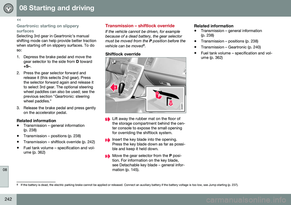
Lift away the rubber mat on the floor of the storage compartment behind the cen-ter console to expose the small openingfor overriding the shiftlock system.
Insert the key blade into the opening. Press the key blade down as far as possi-ble and keep it held down.
Move the gear selector from the P posi-
tion. For information on the key blade, see Detachable key blade – general infor-mation (p. 145).
Related information
• Transmission – general information (p. 238)
• Transmission – positions (p. 238)
• Transmission – Geartronic (p. 240)
• Fuel tank volume – specification and vol-ume (p. 362)
8
If the battery is dead, the electric parking brake cannot be applied or released. Connect an auxiliary battery if the battery voltage is too low, see Jump starting (p. 237).
Page 256 of 380
08 Starting and driving
08
254
Parking brake – general information
The electric parking brake helps to keep the vehicle stationary when it is parked.
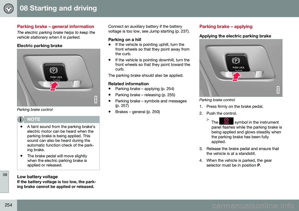
Electric parking brake
Parking brake control
NOTE
•A faint sound from the parking brake's electric motor can be heard when theparking brake is being applied. Thissound can also be heard during theautomatic function check of the park-ing brake.
• The brake pedal will move slightlywhen the electric parking brake isapplied or released.
Low battery voltageIf the battery voltage is too low, the park- ing brake cannot be applied or released. Connect an auxiliary battery if the batteryvoltage is too low, see Jump starting (p. 237).
Parking on a hill
•
If the vehicle is pointing uphill, turn the front wheels so that they point away fromthe curb.
• If the vehicle is pointing downhill, turn thefront wheels so that they point toward thecurb.
The parking brake should also be applied.
Related information
• Parking brake – applying (p. 254)
• Parking brake – releasing (p. 255)
• Parking brake – symbols and messages(p. 257)
• Brakes – general (p. 250)
Parking brake – applying
Applying the electric parking brake
Parking brake control
1. Press firmly on the brake pedal.
2. Push the control. >The
symbol in the instrument
panel flashes while the parking brake is being applied and glows steadily whenthe parking brake has been fullyapplied.
3. Release the brake pedal and ensure that the vehicle is at a standstill.
4. When the vehicle is parked, the gear selector must be in position P.
Page 261 of 380
08 Starting and driving
08
}}
259
Engine and cooling system
Under special conditions, for example when driving in hilly terrain, extreme heat or withheavy loads, there is a risk that the engine andcooling system will overheat. Proceed as follows to avoid overheating the engine. •Maintain a low speed when driving with a trailer up long, steep hills. For informa-tion, see Towing a trailer (p. 267)
• Do not turn the engine off immediatelywhen stopping after a hard drive.
WARNING
The cooling fan may start or continue to operate (for up to 6 minutes) after theengine has been switched off.
•
Remove any auxiliary lights from in front of the grille when driving in hot weatherconditions.
• Do not exceed engine speeds of4500 rpm if driving with a trailer in hillyterrain. The oil temperature could becometoo high.
Conserving electrical current
Keep the following in mind to help minimize battery drain:
• When the engine is not running, avoid using ignition mode
II. Many electrical
systems (the audio system, the optionalnavigation system, power windows, etc)will function in ignition modes 0 and I.
These modes reduce drain on the battery.
• Please keep in mind that using systems,accessories, etc., that consume a greatdeal of current when the engine is notrunning could result in the battery beingcompletely drained. Driving or having theengine running for approximately15 minutes will help keep the batterycharged.
• The optional 12-volt socket in thetrunk (p. 135) area provides electrical cur-rent even with the ignition switched off,which drains the battery.
Before a long distance trip
It is always worthwhile to have your vehicle checked by a trained and qualified Volvo serv-ice technician before driving long distances.Your retailer will also be able to supply youwith bulbs, fuses, spark plugs and wiperblades for your use in the event that problemsoccur. As a minimum, the following items should be checked before any long trip:
• Check that engine runs smoothly and that fuel consumption is normal.
• Check for fuel, oil, and fluid leakage.
• Have the transmission oil level (p. 362)checked.
• Check condition of drive belts.
• Check state of the battery's charge.
• Examine tires carefully (the spare tire aswell), and replace those that areworn (p. 275). Check tire pres-sure (p. 282).
• The brakes, front wheel alignment, andsteering gear should be checked by atrained and qualified Volvo service techni-cian only.
• Check all lights, including high beams.
• Reflective warning triangles are legallyrequired in some states/provinces.
• Have a word with a trained and qualifiedVolvo service technician if you intend to