VOLVO S90 2017 Owner´s Manual
Manufacturer: VOLVO, Model Year: 2017, Model line: S90, Model: VOLVO S90 2017Pages: 548, PDF Size: 11.42 MB
Page 91 of 548
SAFETY
}}
* Option/accessory.89
Raising the integrated booster cushion*
The integrated booster cushions in the rear seat's outboard positions must be correctlyraised before use.
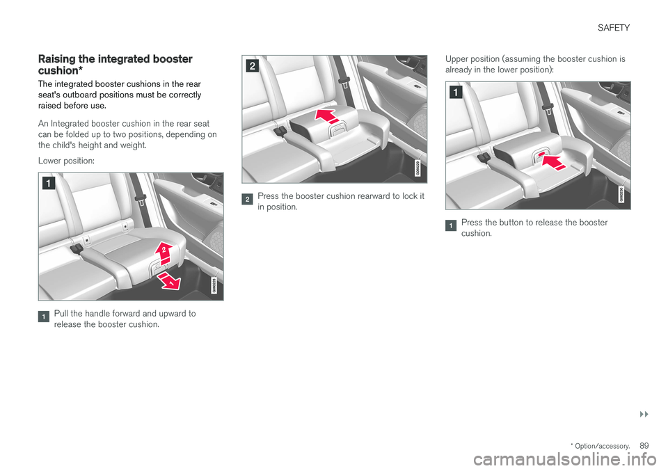
An Integrated booster cushion in the rear seat can be folded up to two positions, depending onthe child's height and weight. Lower position:
Pull the handle forward and upward to release the booster cushion.
Press the booster cushion rearward to lock it in position. Upper position (assuming the booster cushion isalready in the lower position):
Press the button to release the booster cushion.
Page 92 of 548
||
SAFETY
* Option/accessory.
90
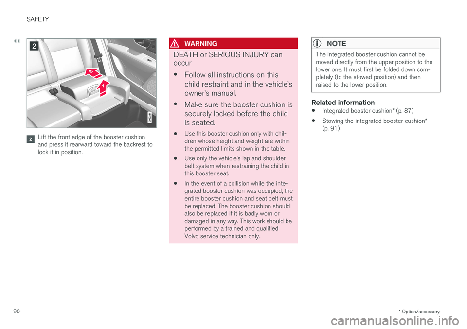
Lift the front edge of the booster cushion and press it rearward toward the backrest tolock it in position.
WARNING
DEATH or SERIOUS INJURY can occur •
Follow all instructions on this child restraint and in the vehicle
Page 93 of 548
SAFETY
}}
* Option/accessory.91
Stowing the integrated booster cushion*
The integrated booster cushions in the rear seat's outboard positions should be stowed(folded down) when not in use.
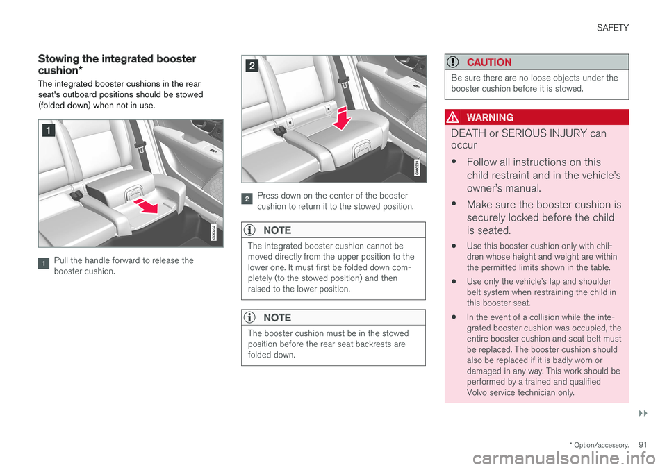
Pull the handle forward to release the booster cushion.
Press down on the center of the booster cushion to return it to the stowed position.
NOTE
The integrated booster cushion cannot be moved directly from the upper position to thelower one. It must first be folded down com-pletely (to the stowed position) and thenraised to the lower position.
NOTE
The booster cushion must be in the stowed position before the rear seat backrests arefolded down.
CAUTION
Be sure there are no loose objects under the booster cushion before it is stowed.
WARNING
DEATH or SERIOUS INJURY can occur • Follow all instructions on this child restraint and in the vehicle
Page 94 of 548
||
SAFETY
* Option/accessory.
92
Related information
• Integrated booster cushion
* (p. 87)
• Raising the integrated booster cushion
*
(p. 89)
Page 95 of 548
I N S T R U M E N T S A N D C O N T R O L S
Page 96 of 548
INSTRUMENTS AND CONTROLS
* Option/accessory.
94
Instruments and controls
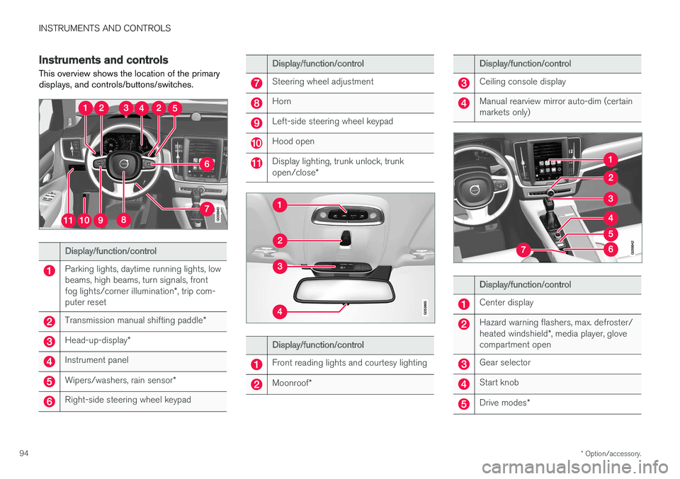
This overview shows the location of the primary displays, and controls/buttons/switches.
Display/function/control
Parking lights, daytime running lights, low beams, high beams, turn signals, front fog lights/corner illumination *, trip com-
puter reset
Transmission manual shifting paddle *
Head-up-display*
Instrument panel
Wipers/washers, rain sensor *
Right-side steering wheel keypad
Display/function/control
Steering wheel adjustment
Horn
Left-side steering wheel keypad
Hood open
Display lighting, trunk unlock, trunk open/close*
Display/function/control
Front reading lights and courtesy lighting
Moonroof*
Display/function/control
Ceiling console display
Manual rearview mirror auto-dim (certain markets only)
Display/function/control
Center display
Hazard warning flashers, max. defroster/ heated windshield *, media player, glove
compartment open
Gear selector
Start knob
Drive modes *
Page 97 of 548
INSTRUMENTS AND CONTROLS
}}
* Option/accessory.95
Display/function/control
Parking brake
Auto-hold brakes
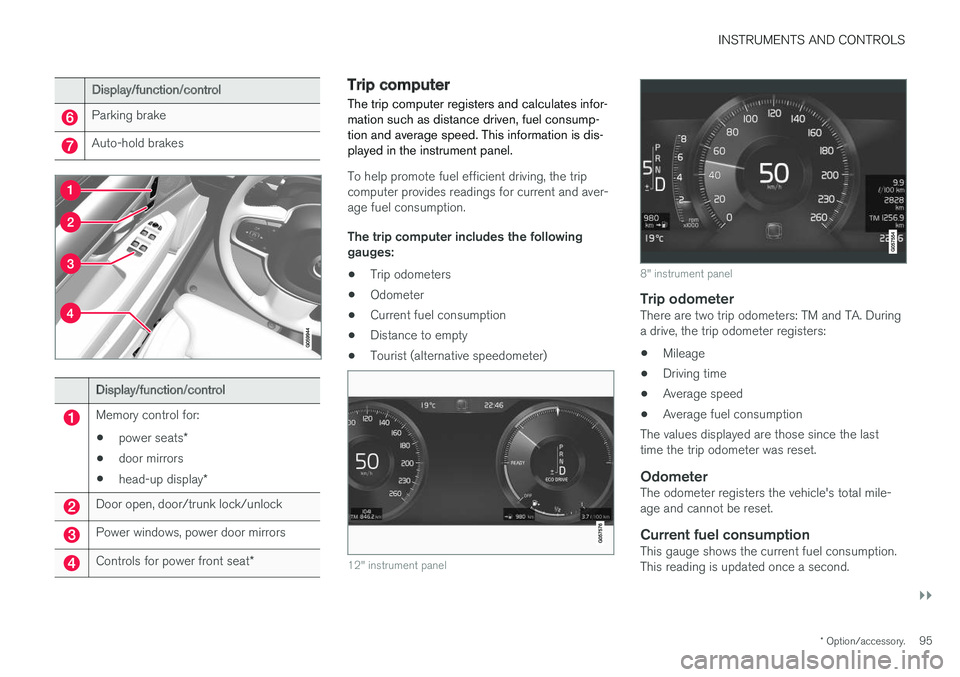
Display/function/control
Memory control for:
• power seats
*
• door mirrors
• head-up display
*
Door open, door/trunk lock/unlock
Power windows, power door mirrors
Controls for power front seat *
Trip computer The trip computer registers and calculates infor- mation such as distance driven, fuel consump-tion and average speed. This information is dis-played in the instrument panel.
To help promote fuel efficient driving, the trip computer provides readings for current and aver-age fuel consumption. The trip computer includes the following gauges:
• Trip odometers
• Odometer
• Current fuel consumption
• Distance to empty
• Tourist (alternative speedometer)
12" instrument panel
8" instrument panel
Trip odometerThere are two trip odometers: TM and TA. During a drive, the trip odometer registers:
• Mileage
• Driving time
• Average speed
• Average fuel consumption
The values displayed are those since the lasttime the trip odometer was reset.
OdometerThe odometer registers the vehicle's total mile-age and cannot be reset.
Current fuel consumptionThis gauge shows the current fuel consumption.This reading is updated once a second.
Page 98 of 548
||
INSTRUMENTS AND CONTROLS
96
Distance to emptyThis function shows the approximate distance that can be driven on the fuel remaining in thetank. The calculation is based on average fuel con- sumption during the last 20 miles (30 km) ofdriving and the amount of fuel remaining in thetank. When the gauge displays "----", there is very little useable fuel remaining in the tank; refuel as soonas possible. The accuracy of this figure may vary if your driv- ing style changes. An economical driving style willgenerally increase this distance.
Tourist (alternative speedometer)This is an alternative digital speedometer can beused when driving in areas in which the speedlimit is listed in a different unit of measure. If the speedometer is in mph, this gauge will show the
vehicle's speed in km/h and vice versa.
Related information
•Displaying trip computer information (p. 96)
• Displaying trip statistics (p. 97)
Displaying trip computer information
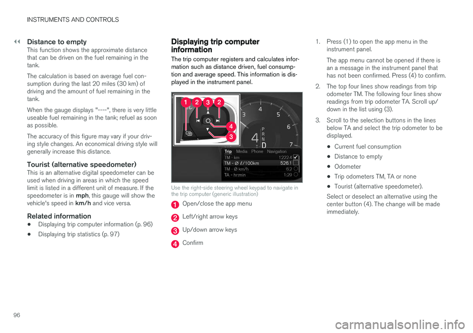
The trip computer registers and calculates infor- mation such as distance driven, fuel consump-tion and average speed. This information is dis-played in the instrument panel.
Use the right-side steering wheel keypad to navigate in the trip computer (generic illustration)
Open/close the app menu
Left/right arrow keys
Up/down arrow keys
Confirm 1. Press (1) to open the app menu in the
instrument panel. The app menu cannot be opened if there is an a message in the instrument panel thathas not been confirmed. Press (4) to confirm.
2. The top four lines show readings from trip odometer TM. The following four lines showreadings from trip odometer TA. Scroll up/down in the list using (3).
3. Scroll to the selection buttons in the lines below TA and select the trip odometer to bedisplayed.
• Current fuel consumption
• Distance to empty
• Odometer
• Trip odometers TM, TA or none
• Tourist (alternative speedometer).
Select or deselect an alternative using thecenter button (4). The change will be madeimmediately.
Page 99 of 548
INSTRUMENTS AND CONTROLS
}}
* Option/accessory.97
Resetting a trip odometer
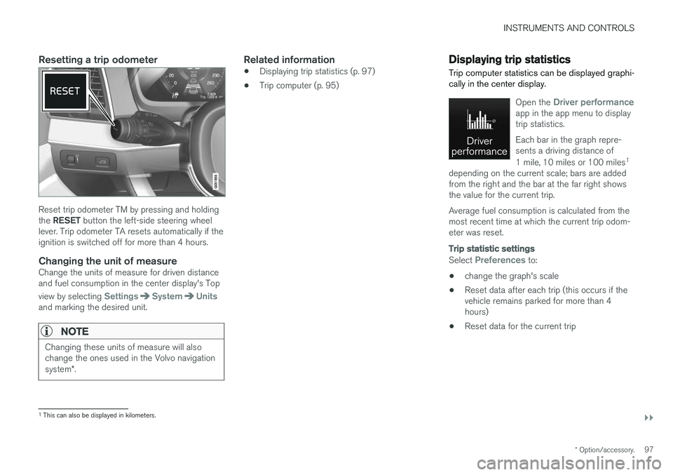
Reset trip odometer TM by pressing and holding the RESET button the left-side steering wheel
lever. Trip odometer TA resets automatically if the ignition is switched off for more than 4 hours.
Changing the unit of measureChange the units of measure for driven distanceand fuel consumption in the center display's Top view by selecting
SettingsSystemUnitsand marking the desired unit.
NOTE
Changing these units of measure will also change the ones used in the Volvo navigation system *.
Related information
• Displaying trip statistics (p. 97)
• Trip computer (p. 95)
Displaying trip statistics Trip computer statistics can be displayed graphi- cally in the center display.
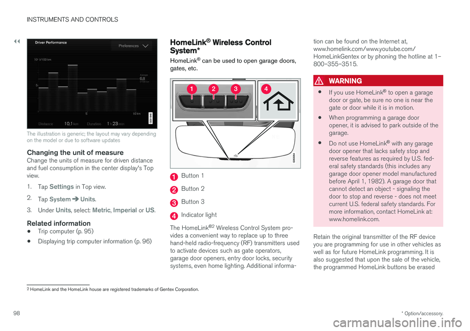
Open the Driver performanceapp in the app menu to display trip statistics. Each bar in the graph repre- sents a driving distance of 1 mile, 10 miles or 100 miles 1
depending on the current scale; bars are added from the right and the bar at the far right showsthe value for the current trip. Average fuel consumption is calculated from the most recent time at which the current trip odom-eter was reset.
Trip statistic settings
Select Preferences to:
• change the graph's scale
• Reset data after each trip (this occurs if the vehicle remains parked for more than 4hours)
• Reset data for the current trip
1
This can also be displayed in kilometers.
Page 100 of 548
||
INSTRUMENTS AND CONTROLS
* Option/accessory.
98
The illustration is generic; the layout may vary depending on the model or due to software updates
Changing the unit of measureChange the units of measure for driven distance and fuel consumption in the center display's Topview. 1.
Tap
Settings in Top view.
2. Tap
SystemUnits.
3. Under
Units, select: Metric, Imperial or US.
Related information
• Trip computer (p. 95)
• Displaying trip computer information (p. 96)
HomeLink ®
Wireless Control
System *
HomeLink ®
can be used to open garage doors,
gates, etc.
Button 1
Button 2
Button 3
Indicator light
The HomeLink ®
2
Wireless Control System pro-
vides a convenient way to replace up to three hand-held radio-frequency (RF) transmitters usedto activate devices such as gate operators,garage door openers, entry door locks, securitysystems, even home lighting. Additional informa- tion can be found on the Internet at,www.homelink.com/www.youtube.com/HomeLinkGentex or by phoning the hotline at 1–800–355–3515.
WARNING
•
If you use HomeLink ®
to open a garage
door or gate, be sure no one is near the gate or door while it is in motion.
• When programming a garage dooropener, it is advised to park outside of thegarage.
• Do not use HomeLink ®
with any garage
door opener that lacks safety stop andreverse features as required by U.S. fed-eral safety standards (this includes anygarage door opener model manufacturedbefore April 1, 1982). A garage door thatcannot detect an object - signaling thedoor to stop and reverse - does not meetcurrent U.S. federal safety standards. Formore information, contact HomeLink at:www.homelink.com.
Retain the original transmitter of the RF deviceyou are programming for use in other vehicles aswell as for future HomeLink programming. It isalso suggested that upon the sale of the vehicle,the programmed HomeLink buttons be erased
2 HomeLink and the HomeLink house are registered trademarks of Gentex Corporation.