VOLVO S90 2017 Owner´s Manual
Manufacturer: VOLVO, Model Year: 2017, Model line: S90, Model: VOLVO S90 2017Pages: 548, PDF Size: 11.42 MB
Page 211 of 548
LOADING AND STORAGE
}}}}
* Option/accessory.209
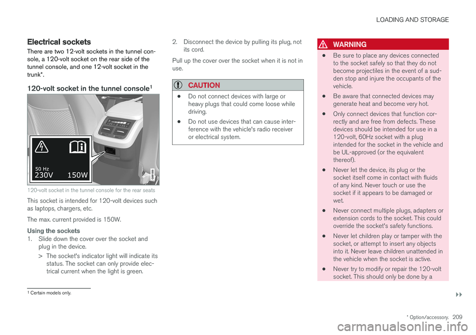
Electrical sockets There are two 12-volt sockets in the tunnel con- sole, a 120-volt socket on the rear side of thetunnel console, and one 12-volt socket in the trunk*.
120-volt socket in the tunnel console 1
120-volt socket in the tunnel console for the rear seats
This socket is intended for 120-volt devices such as laptops, chargers, etc. The max. current provided is 150W.
Using the sockets
1. Slide down the cover over the socket and
plug in the device.
> The socket's indicator light will indicate itsstatus. The socket can only provide elec- trical current when the light is green. 2. Disconnect the device by pulling its plug, not
its cord.
Pull up the cover over the socket when it is not inuse.
CAUTION
• Do not connect devices with large or heavy plugs that could come loose whiledriving.
• Do not use devices that can cause inter-ference with the vehicle's radio receiveror electrical system.
WARNING
•
Be sure to place any devices connected to the socket safely so that they do notbecome projectiles in the event of a sud-den stop and injure the occupants of thevehicle.
• Be aware that connected devices maygenerate heat and become very hot.
• Only connect devices that function cor-rectly and are free from defects. Thesedevices should be intended for use in a120-volt, 60Hz socket with a plugintended for the socket in the vehicle andbe UL-approved (or the equivalentthereof).
• Never let the device, its plug or thesocket itself come in contact with fluidsof any kind. Never touch or use thesocket if it appears to be damaged orwet.
• Never connect multiple plugs, adapters orextension cords to the socket. This couldoverride the socket's safety functions.
• Never let children play or tamper with thesocket, or attempt to insert any objectsinto it. Never leave children unattended inthe vehicle when the socket is active.
• Never try to modify or repair the 120-voltsocket. This should only be done by a
1
Certain models only.
Page 212 of 548
||
LOADING AND STORAGE
210
trained and qualified Volvo service techni- cian.
Failure to follow the points above could result in electrical shock and/or serious injury.Status indication
An LED (Light Emitting Diode) on the socket indicates its status:
Status indicator light Socket status Action
Steady green light The socket is providing current to a connected device. None.
Flashing orange light The socket's voltage converter is too hot (the connected device draws too much current, etc. or the temperature in the passenger compartment is very high). Unplug the device, let the converter cool down and plug in the device again.
The connected device draws too much current (constantly or currently) or is notfunctioning properly. None. The device should not be plugged into thesocket.
Indicator light off The socket has not detected a plugged in device. Be sure the device is correctly plugged into the socket.
The socket is not active. Put the vehicle's ignition in at least mode I.
The socket has been active but has been deactivated. Start the engine and/or charge the start battery.
If a problem persists, have the socket checked by a trained and qualified Volvo service technician.
Page 213 of 548
LOADING AND STORAGE
211
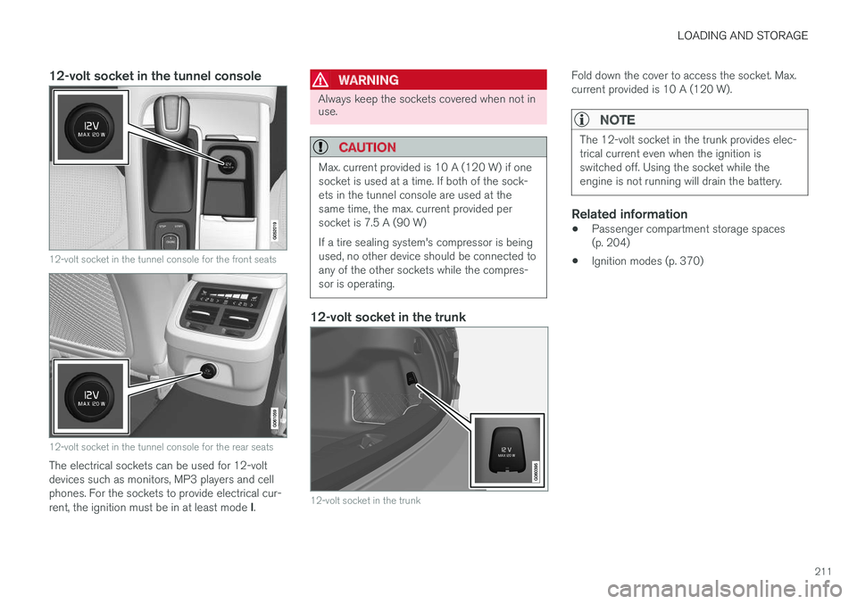
12-volt socket in the tunnel console
12-volt socket in the tunnel console for the front seats
12-volt socket in the tunnel console for the rear seats
The electrical sockets can be used for 12-volt devices such as monitors, MP3 players and cellphones. For the sockets to provide electrical cur- rent, the ignition must be in at least mode I.
WARNING
Always keep the sockets covered when not in use.
CAUTION
Max. current provided is 10 A (120 W) if one socket is used at a time. If both of the sock-ets in the tunnel console are used at thesame time, the max. current provided persocket is 7.5 A (90 W) If a tire sealing system's compressor is being used, no other device should be connected toany of the other sockets while the compres-sor is operating.
12-volt socket in the trunk
12-volt socket in the trunk
Fold down the cover to access the socket. Max. current provided is 10 A (120 W).
NOTE
The 12-volt socket in the trunk provides elec- trical current even when the ignition isswitched off. Using the socket while theengine is not running will drain the battery.
Related information
• Passenger compartment storage spaces (p. 204)
• Ignition modes (p. 370)
Page 214 of 548

Page 215 of 548

L O C K S A N D A L A R M
Page 216 of 548
LOCKS AND ALARM
* Option/accessory.
214
Locks and remote keys
The vehicle can be locked and unlocked in vari- ous ways and there are several types of remotekeys that can be used.
Locking/unlocking/opening/closingThe vehicle can be locked/unlocked from the passenger compartment, using the buttons onthe remote key or by using the optional PassiveEntry system where it is only necessary to have akey in your possession to lock or unlock thedoors. On models equipped with a power trunk *, it can
also be opened/closed by moving your foot under a sensor * beneath the rear bumper.
If for any reason a remote key does not function properly, it may be necessary to replace its bat-teries but the vehicle can always be locked orunlocked manually using the remote key'sdetachable key blade.
Remote keyThe remote key does not have to be physicallyhandled in order to start the engine because thevehicle is equipped with the standard PassiveStart system (the key only needs to be in thefront part of the passenger compartment). If thevehicle is equipped with the optional PassiveEntry system that enables keyless entry and start,the key can be anywhere in the vehicle when theengine is started. Models with Passive Entry
* also have an extra,
smaller key without buttons called a Key Tag. Additional keys can be ordered from a Volvo retailer.
Related information
• Immobilizer (p. 214)
• Alarm (p. 236)
• Child safety locks (p. 238)
• Remote key (p. 217)
• Foot movement trunk operation
* (p. 232)
• Locking/unlocking from inside the vehicle(p. 224)
• Locking/unlocking from outside the vehicle(p. 223)
• Locking/unlocking the trunk (p. 228)
• Starting the engine (p. 372)
Immobilizer
The immobilizer is a start inhibitor that helps pre- vent unauthorized persons from starting theengine.
Each of the keys supplied with your vehicle con- tains a unique coded transponder. The vehiclecode in the key is transmitted to the vehicle'signition system where it is compared to the codestored in the start inhibitor module. The following message (which may appear in the instrument panel) is related to the immobilizer:
Symbol Message Explanation
Vehicle key not found See Owner'smanualRemote key not recognized duringstart. Place theremote key on thekey symbol in thetunnel console cupholder and try tostart the vehicleagain.
Related information
•Remote key's range (p. 219)
• Remote key (p. 217)
Page 217 of 548
LOCKS AND ALARM
}}
215
Changing the remote key's battery The remote key can be opened if the battery needs to be replaced.
The battery should be replaced if:The information symbol illuminates and
Vehicle key bat. low See Owner's
manual is displayed in the instrument
panel.
and/or if the locks do not react after several attempts to unlock or lock the vehicle with the remote keywithin approx. 65 feet (20 meters) of the vehicle.
NOTE
If the locks do not react, move closer to the vehicle and try to unlock it again.
The battery in the smaller extra key without but- tons (Key Tag) provided with models with theoptional Passive Entry system cannot bereplaced. A new Key Tag can be ordered from aVolvo retailer.
NOTE
A Key Tag with a depleted battery should be returned to an authorized Volvo retailer. Thekey should also be erased from the vehicle'selectrical system because it could still beused to start the vehicle from the back-upstart system.
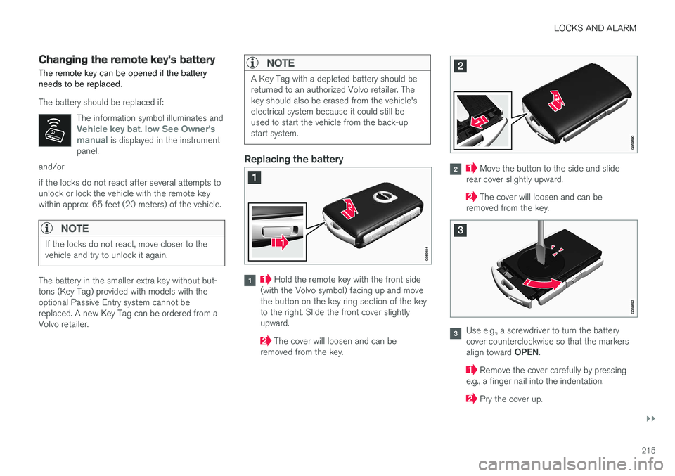
Replacing the battery
Hold the remote key with the front side
(with the Volvo symbol) facing up and move the button on the key ring section of the keyto the right. Slide the front cover slightlyupward.
The cover will loosen and can be
removed from the key.
Move the button to the side and slide
rear cover slightly upward.
The cover will loosen and can be
removed from the key.
Use e.g., a screwdriver to turn the battery cover counterclockwise so that the markers align toward OPEN.
Remove the cover carefully by pressing
e.g., a finger nail into the indentation.
Pry the cover up.
Page 218 of 548
||
LOCKS AND ALARM
216
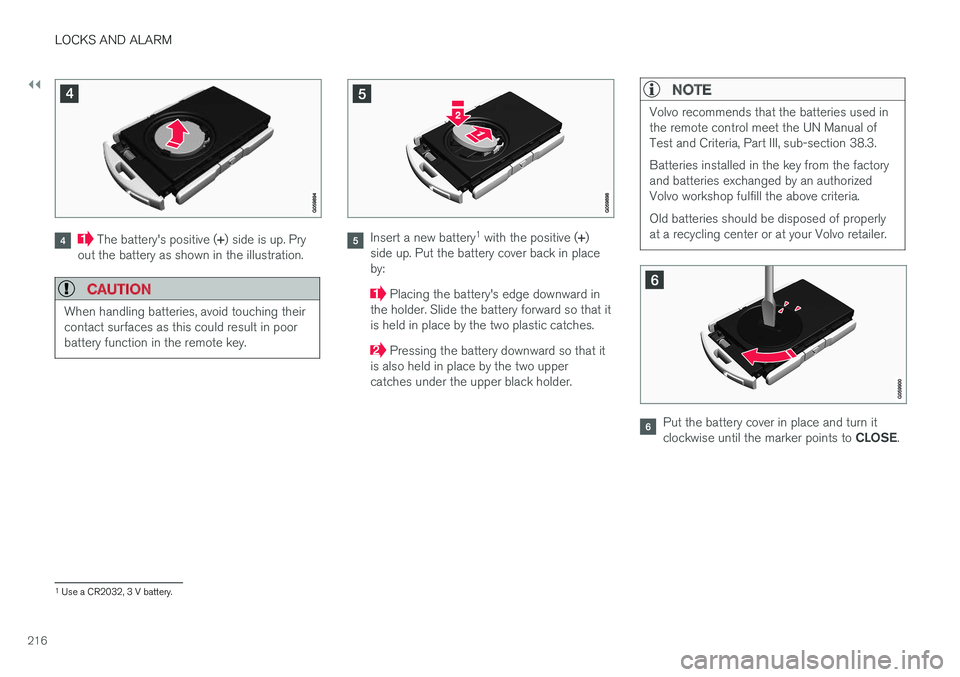
The battery's positive (+) side is up. Pry
out the battery as shown in the illustration.
CAUTION
When handling batteries, avoid touching their contact surfaces as this could result in poorbattery function in the remote key.
Insert a new battery 1
with the positive ( +)
side up. Put the battery cover back in place by:
Placing the battery's edge downward in
the holder. Slide the battery forward so that it is held in place by the two plastic catches.
Pressing the battery downward so that it
is also held in place by the two upper catches under the upper black holder.
NOTE
Volvo recommends that the batteries used in the remote control meet the UN Manual ofTest and Criteria, Part III, sub-section 38.3. Batteries installed in the key from the factory and batteries exchanged by an authorizedVolvo workshop fulfill the above criteria. Old batteries should be disposed of properly at a recycling center or at your Volvo retailer.
Put the battery cover in place and turn it clockwise until the marker points to CLOSE.
1
Use a CR2032, 3 V battery.
Page 219 of 548
LOCKS AND ALARM
}}
217
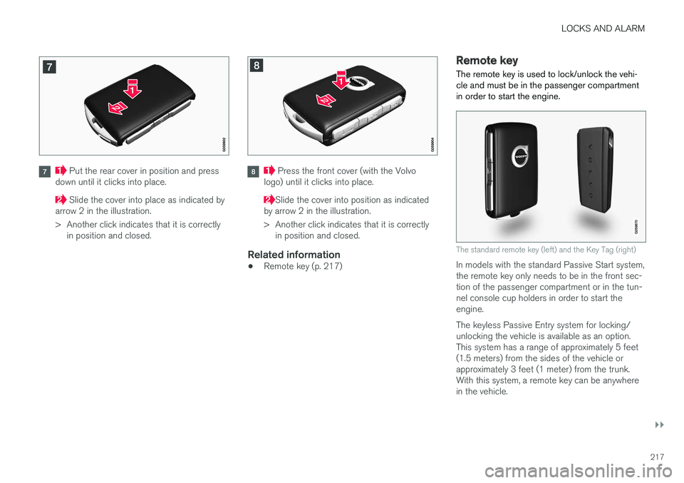
Put the rear cover in position and press
down until it clicks into place.
Slide the cover into place as indicated by
arrow 2 in the illustration.
> Another click indicates that it is correctly in position and closed.
Press the front cover (with the Volvo
logo) until it clicks into place.
Slide the cover into position as indicated
by arrow 2 in the illustration.
> Another click indicates that it is correctly in position and closed.
Related information
• Remote key (p. 217)
Remote key
The remote key is used to lock/unlock the vehi- cle and must be in the passenger compartmentin order to start the engine.
The standard remote key (left) and the Key Tag (right)
In models with the standard Passive Start system, the remote key only needs to be in the front sec-tion of the passenger compartment or in the tun-nel console cup holders in order to start theengine. The keyless Passive Entry system for locking/ unlocking the vehicle is available as an option.This system has a range of approximately 5 feet(1.5 meters) from the sides of the vehicle orapproximately 3 feet (1 meter) from the trunk.With this system, a remote key can be anywherein the vehicle.
Page 220 of 548
||
LOCKS AND ALARM
* Option/accessory.
218 Each of the remote keys provided with the vehicle can be linked to a driver profile containing uniquepersonal settings that will be applied when thatparticular key is used. See also the article "Driverprofile" for additional information.
NOTE
Avoid placing the remote key closer than approx. (4-6 in.) (10-15 cm) to any metallicobjects or electronic devices such as cellphones, tablets, laptops or chargers.
If interference persists, unlock the vehicle with the detachable key blade and place the remotekey in the backup key reader in the tunnel con-sole cup holder to disarm the alarm.
WARNING
Always remove the remote key from the pas- senger compartment when leaving the vehicle and ensure that the ignition in mode
0, espe-
cially if there are children in the vehicle.
Key TagIn addition to the two remote keys provided, a smaller third key, called a Key Tag, is also provi-ded for vehicles equipped with the optionalPassive Entry system. This key functions in the same way as a standardremote key but does not have a detachable keyblade and its battery cannot be replaced; a newKey Tag has to be ordered.
Ordering new keysTwo remote keys are provided with the vehicle (a Key Tag
2
is also included for vehicles equipped
with the optional Passive Entry system). Addi- tional keys (a total of 12) can be ordered andused with the vehicle.
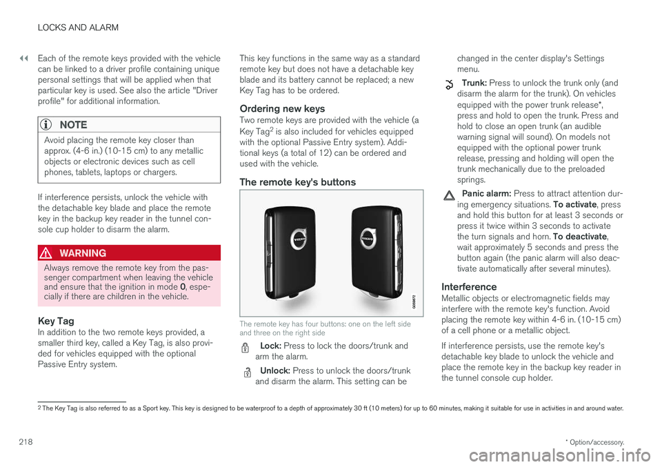
The remote key's buttons
The remote key has four buttons: one on the left side and three on the right side
Lock: Press to lock the doors/trunk and
arm the alarm.
Unlock: Press to unlock the doors/trunk
and disarm the alarm. This setting can be changed in the center display's Settings menu.
Trunk: Press to unlock the trunk only (and
disarm the alarm for the trunk). On vehicles equipped with the power trunk release *,
press and hold to open the trunk. Press and hold to close an open trunk (an audiblewarning signal will sound). On models notequipped with the optional power trunkrelease, pressing and holding will open thetrunk mechanically due to the preloadedsprings.
Panic alarm: Press to attract attention dur-
ing emergency situations. To activate, press
and hold this button for at least 3 seconds or press it twice within 3 seconds to activate the turn signals and horn. To deactivate,
wait approximately 5 seconds and press the button again (the panic alarm will also deac-tivate automatically after several minutes).
InterferenceMetallic objects or electromagnetic fields mayinterfere with the remote key's function. Avoidplacing the remote key within 4-6 in. (10-15 cm)of a cell phone or a metallic object. If interference persists, use the remote key's detachable key blade to unlock the vehicle andplace the remote key in the backup key reader inthe tunnel console cup holder.
2 The Key Tag is also referred to as a Sport key. This key is designed to be waterproof to a depth of approximately 30 ft (10 meters) for up to 60 minutes, making it suitable for use in activities in and around water.