light VOLVO V4 2002 Owner's Manual
[x] Cancel search | Manufacturer: VOLVO, Model Year: 2002, Model line: V4, Model: VOLVO V4 2002Pages: 88, PDF Size: 2.34 MB
Page 49 of 88
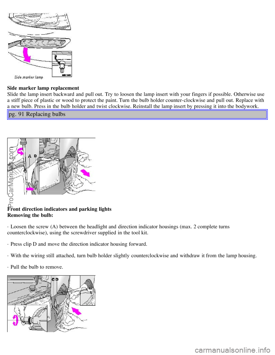
Side marker lamp replacement
Slide the lamp insert backward and pull out. Try to loosen the lamp insert with your fingers if possible. Otherwise use
a stiff piece of plastic or wood to protect the paint. Turn the bulb holder counter-clockwise and pull out. Replace with
a new bulb. Press in the bulb holder and twist clockwise. Reinstall the lamp insert by pressing it into the bodywork.
pg. 91 Replacing bulbs
Front direction indicators and parking lights
Removing the bulb:
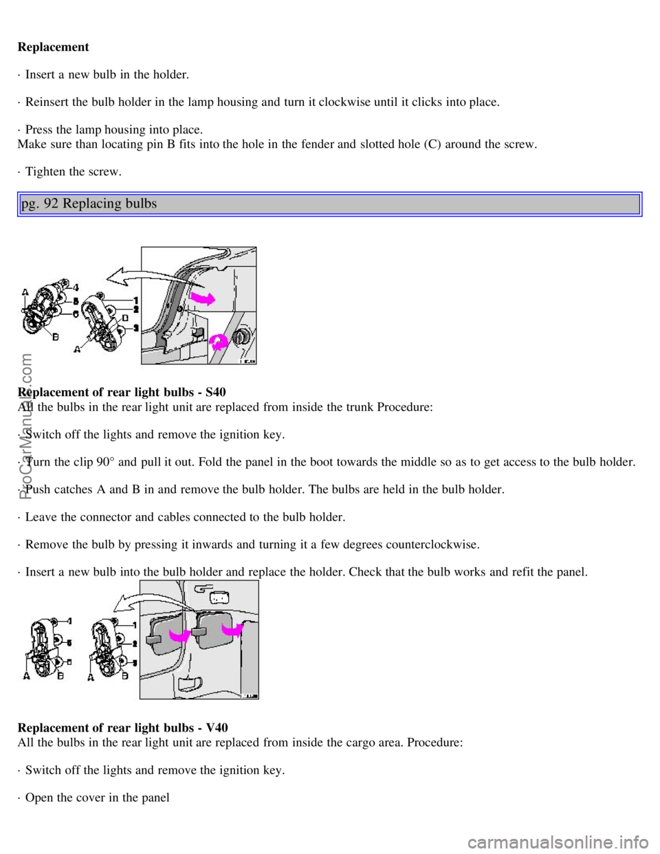
· Loosen the screw (A) between the headlight and direction indicator housings (max. 2 complete turns
counterclockwise), using the screwdriver supplied in the tool kit.
· Press clip D and move the direction indicator housing forward.
· With the wiring still attached, turn bulb holder slightly counterclockwise and withdraw it from the lamp housing.
· Pull the bulb to remove.
ProCarManuals.com
Page 50 of 88
Replacement
· Insert a new bulb in the holder.
· Reinsert the bulb holder in the lamp housing and turn it clockwise until it clicks into place.
· Press the lamp housing into place.
Make sure than locating pin B fits into the hole in the fender and slotted hole (C) around the screw.
· Tighten the screw.
pg. 92 Replacing bulbs
Replacement of rear light bulbs - S40
All the bulbs in the rear light unit are replaced from inside the trunk Procedure:
· Switch off the lights and remove the ignition key.
· Turn the clip 90° and pull it out. Fold the panel in the boot towards the middle so as to get access to the bulb holder.
· Push catches A and B in and remove the bulb holder. The bulbs are held in the bulb holder.
· Leave the connector and cables connected to the bulb holder.
· Remove the bulb by pressing it inwards and turning it a few degrees counterclockwise.
· Insert a new bulb into the bulb holder and replace the holder. Check that the bulb works and refit the panel.
Replacement of rear light bulbs - V40
All the bulbs in the rear light unit are replaced from inside the cargo area. Procedure:
· Switch off the lights and remove the ignition key.
· Open the cover in the panel
ProCarManuals.com
Page 51 of 88

· Push catches A and B in and remove the bulb holder. The bulbs are held in the bulb holder.
· Leave the connector and cables connected to the bulb holder.
· Remove the bulb by pressing it inwards and turning it a few degrees counterclockwise.
· Insert a new bulb into the bulb holder and replace the holder. Check that the bulb works and refit the cover.
1 Tail light (rear parking light) 5W
2 Direction indicator 21W
3 Brake light 21W
4 Tail light 5W
5 Backup light 21W
6 Rear fog light (LH side only) 21W
pg. 93 Replacing bulbs
Side direction indicator
1. Slide the lens forward and pull out the rear edge.
2. Pull out the entire lens/bulb unit.
3. With the lens toward you, turn the bulb holder 1/4 turn (the wires should not be disconnected from the holder) and
pull out the bulb holder from the lens unit.
4. Pull the old bulb straight out and press a new one into place.
5. Replace the entire unit in the reverse order.
Insert screwdriver, turn and pull downward
Front courtesy lights
· Switch off the ignition.
· Insert a flat screwdriver and turn carefully to loosen the glass lens.
ProCarManuals.com
Page 52 of 88
· Replace the bulb and press the glass lens back into place.
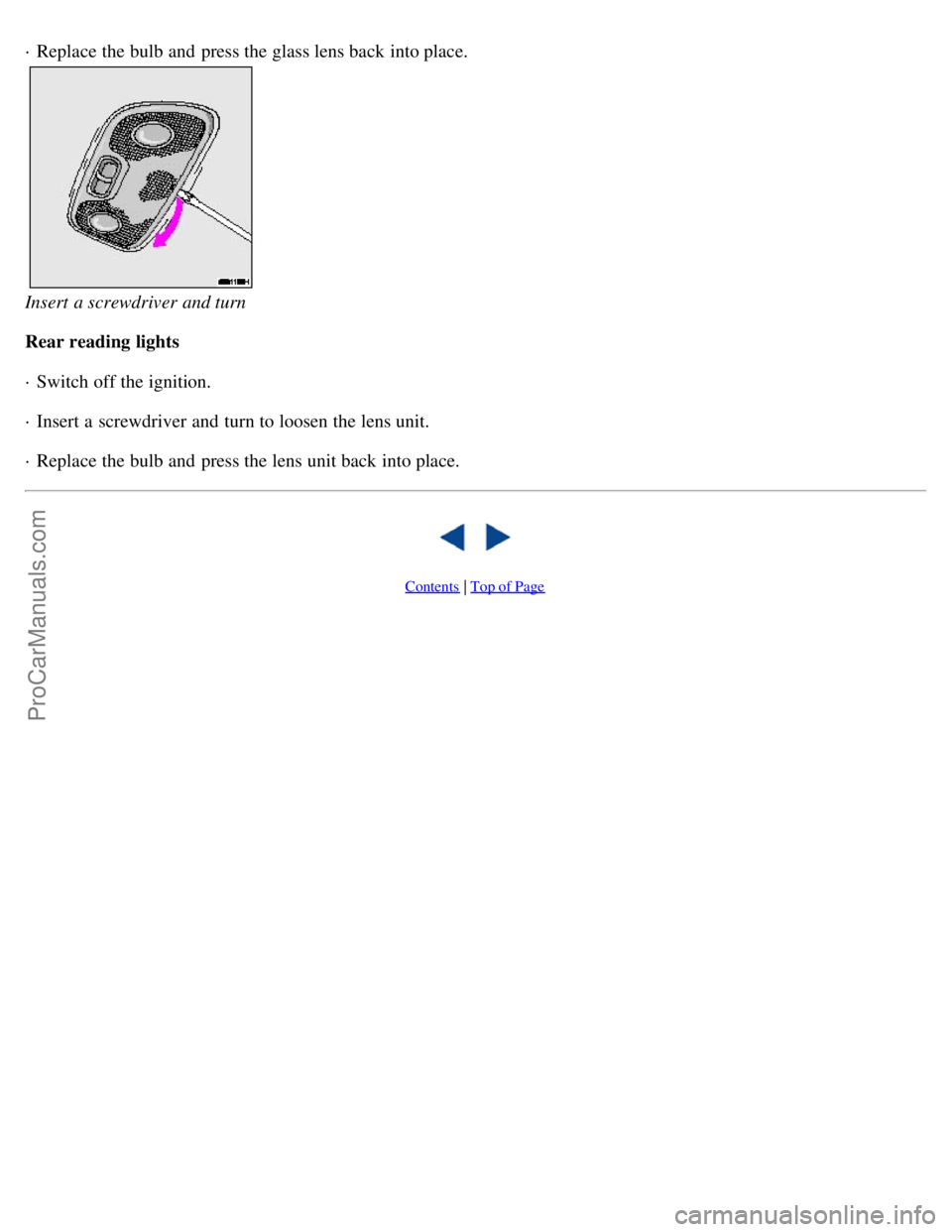
Insert a screwdriver and turn
Rear reading lights
· Switch off the ignition.
· Insert a screwdriver and turn to loosen the lens unit.
· Replace the bulb and press the lens unit back into place.
Contents | Top of Page
ProCarManuals.com
Page 54 of 88
NOTE: When touching up the car, it should be clean and dry. The surface temperature should be above 60° F (15° C).
Scratches on the surface
If the stone chip has not penetrated down to the metal and an undamaged layer of paint remains, the touchup paint can
be applied as soon as the spot has been cleaned.
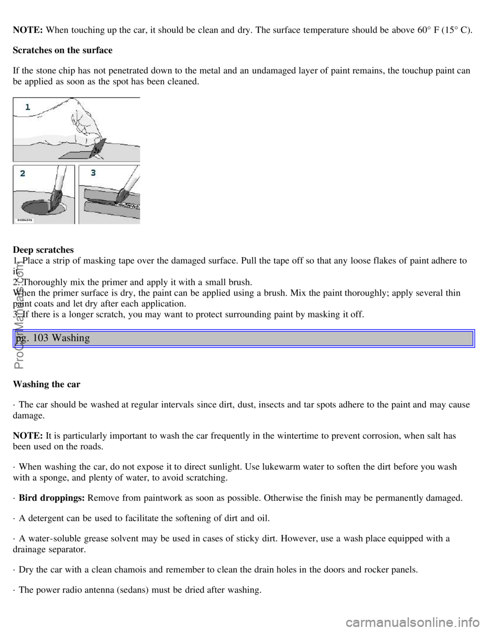
Deep scratches
1. Place a strip of masking tape over the damaged surface. Pull the tape off so that any loose flakes of paint adhere to
it.
2. Thoroughly mix the primer and apply it with a small brush.
When the primer surface is dry, the paint can be applied using a brush. Mix the paint thoroughly; apply several thin
paint coats and let dry after each application.
3. If there is a longer scratch, you may want to protect surrounding paint by masking it off.
pg. 103 Washing
Washing the car
· The car should be washed at regular intervals since dirt, dust, insects and tar spots adhere to the paint and may cause
damage.
NOTE: It is particularly important to wash the car frequently in the wintertime to prevent corrosion, when salt has
been used on the roads.
· When washing the car, do not expose it to direct sunlight. Use lukewarm water to soften the dirt before you wash
with a sponge, and plenty of water, to avoid scratching.
· Bird droppings: Remove from paintwork as soon as possible. Otherwise the finish may be permanently damaged.
· A detergent can be used to facilitate the softening of dirt and oil.
· A water-soluble grease solvent may be used in cases of sticky dirt. However, use a wash place equipped with a
drainage separator.
· Dry the car with a clean chamois and remember to clean the drain holes in the doors and rocker panels.
· The power radio antenna (sedans) must be dried after washing.
ProCarManuals.com
Page 61 of 88
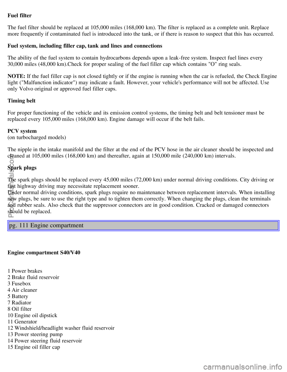
Fuel filter
The fuel filter should be replaced at 105,000 miles (168,000 km). The filter is replaced as a complete unit. Replace
more frequently if contaminated fuel is introduced into the tank, or if there is reason to suspect that this has occurred.
Fuel system, including filler cap, tank and lines and connections
The ability of the fuel system to contain hydrocarbons depends upon a leak-free system. Inspect fuel lines every
30,000 miles (48,000 km).Check for proper sealing of the fuel filler cap which contains "O" ring seals.
NOTE: If the fuel filler cap is not closed tightly or if the engine is running when the car is refueled, the Check Engine
light ("Malfunction indicator") may indicate a fault. However, your vehicle's performance will not be affected. Use
only Volvo original or approved fuel filler caps.
Timing belt
For proper functioning of the vehicle and its emission control systems, the timing belt and belt tensioner must be
replaced every 105,000 miles (168,000 km). Engine damage will occur if the belt fails.
PCV system
(on turbocharged models)
The nipple in the intake manifold and the filter at the end of the PCV hose in the air cleaner should be inspected and
cleaned at 105,000 miles (168,000 km) and thereafter, again at 150,000 mile (240,000 km) intervals.
Spark plugs
The spark plugs should be replaced every 45,000 miles (72,000 km) under normal driving conditions. City driving or
fast highway driving may necessitate replacement sooner.
Under normal driving conditions, spark plugs require no maintenance between replacement intervals. When installing
new plugs, be sure to use the right type and to tighten them correctly. When changing the plugs, clean the terminals
and rubber seals. Also check that the suppressor connectors are in good condition. Cracked or damaged connectors
should be replaced.
pg. 111 Engine compartment
Engine compartment S40/V40
1 Power brakes
2 Brake fluid reservoir
3 Fusebox
4 Air cleaner
5 Battery
7 Radiator
8 Oil filter
10 Engine oil dipstick
11 Generator
12 Windshield/headlight washer fluid reservoir
13 Power steering pump
14 Power steering fluid reservoir
15 Engine oil filler cap
ProCarManuals.com
Page 63 of 88

atmosphere.
The system consists of a fuel tank with filler pipe and cap, a rollover valve, a Fill Limit Vent Valve (FLVV), vapor
vent lines, a charcoal canister, a purge line, a purge control valve and engine connections*.
In addition, there is a pressure sensor connected to the fuel tank and a filter -protected Canister Close Valve (CCV) on
the atmospheric side of the canister, for system diagnosis.
The gasoline vapor is channeled through the rollover valve and the FLVV via the vapor vent lines into the charcoal
canister, where it is
stored. When the engine is started, the gasoline vapor is drawn from the charcoal canister to the engine's air intake
system and into the combustion process.
NOTE:
· If the fuel filler cap is not closed tightly or if the engine is running when the car is refueled, the Malfunction Indicator
light may indicate a fault.
· During a transitional period, a small number of service stations may still have fuel nozzles that are not compatible
with the fuel filler neck on cars equipped with the evaporative control system (ORVR) mandated by the U.S.
Environmental Protection Agency and the California Air Resources Board. If you experience difficulties in refueling
your vehicle, please ask the gas station attendant for assistance.
CAUTION:
Fuel must not be siphoned from the fuel tank. This will damage the Evaporative control system.
Contents | Top of Page
ProCarManuals.com
Page 68 of 88
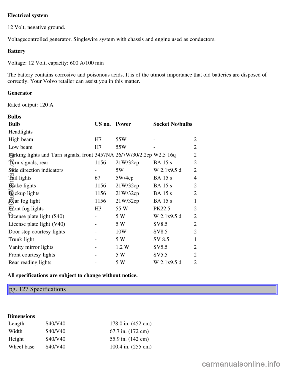
Electrical system
12 Volt, negative ground.
Voltagecontrolled generator. Singlewire system with chassis and engine used as conductors.
Battery
Voltage: 12 Volt, capacity: 600 A/100 min
The battery contains corrosive and poisonous acids. It is of the utmost importance that old batteries are disposed of
correctly. Your Volvo retailer can assist you in this matter.
Generator
Rated output: 120 A
BulbsBulb US no.Power Socket No/bulbs
Headlights
High beam H755W - 2
Low beam H755W - 2
Parking lights and Turn signals, front 3457NA26/7W/30/2.2cp W2.5 16q 2
Turn signals, rear 115621W/32cp BA 15 s 2
Side direction indicators -5W W 2.1x9.5 d 2
Tail lights 675W/4cp BA 15 s 4
Brake lights 115621W/32cp BA 15 s 2
Backup lights 115621W/32cp BA 15 s 2
Rear fog light 115621W/32cp BA 15 s 1
Front fog lights H355 W PK22.5 2
License plate light (S40) -5 W W 2.1x9.5 d 2
License plate light (V40) -5 W SV8.5 2
Door step courtesy lights -10W SV8.5 2
Trunk light -5 W SV 8.5 1
Vanity mirror lights -1.2 W SV5.5 2
Front courtesy lights -5 W SV5.5 2
Rear reading lights -5 W W 2.1x9.5 d 2
All specifications are subject to change without notice.
pg. 127 Specifications
Dimensions Length S40/V40 178.0 in. (452 cm)
Width S40/V40 67.7 in. (172 cm)
Height S40/V40 55.9 in. (142 cm)
Wheel base S40/V40 100.4 in. (255 cm)
ProCarManuals.com
Page 72 of 88

the ignition key must be turned to position I >LI ? the unit must be turned on Make sure the headlights are turned off
to help prevent battery drain.
Enter the code again once 2 hours have elapsed.
pg. 131 Audio system HU-415
1. Switch On/off (push) Volume (turn)
2. Selector knob:
Select the channel (turn)
CD changer - Selecting disc (turn)
Program radio frequency in a channel (push)
3. Selector knob for choosing (turn) :
Radio
Cassette
CD changer
Mode knob (push) for setting: Bass, Treble, Fader and Balance
4. Radio - Station seek up/down
Cassette position - Selecting next/previous track
CD position - Selecting next/previous track
5. Radio - Manual station selection
Cassette position - Fast winding forward/ backwards
CD-position - Fast winding forwards/ backwards
6. Display
7. Random for CD (Description for CD is applicable when a CD Changer is connected)
8. SCAN
9. Dolby B NR noise reduction
10. Auto store of radio stations
11. Tape direction selector/
12. Cassette opening
13. Tape eject
pg. 132 Audio system HU-615
ProCarManuals.com
Page 80 of 88
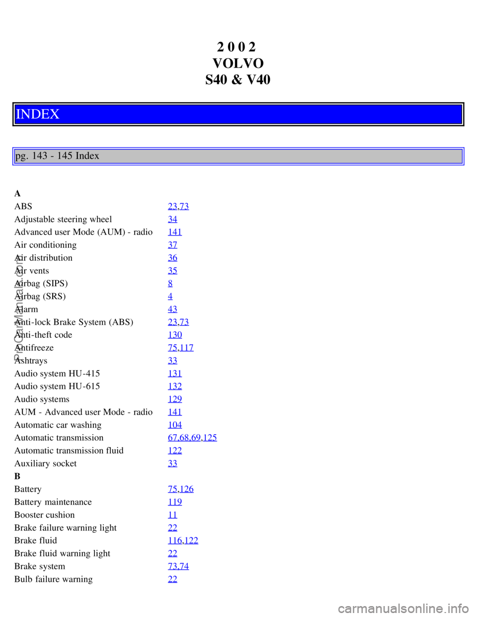
2 0 0 2
VOLVO
S40 & V40
INDEX
pg. 143 - 145 Index
A
ABS 23
,73
Adjustable steering wheel34
Advanced user Mode (AUM) - radio141
Air conditioning37
Air distribution36
Air vents35
Airbag (SIPS)8
Airbag (SRS)4
Alarm43
Anti-lock Brake System (ABS)23,73
Anti-theft code130
Antifreeze75,117
Ashtrays33
Audio system HU -415131
Audio system HU -615132
Audio systems129
AUM - Advanced user Mode - radio141
Automatic car washing104
Automatic transmission67,68,69,125
Automatic transmission fluid122
Auxiliary socket33
B
Battery75
,126
Battery maintenance119
Booster cushion11
Brake failure warning light22
Brake fluid116,122
Brake fluid warning light22
Brake system73,74
Bulb failure warning22
ProCarManuals.com