light VOLVO V4 2004 Owner's Manual
[x] Cancel search | Manufacturer: VOLVO, Model Year: 2004, Model line: V4, Model: VOLVO V4 2004Pages: 89, PDF Size: 2.05 MB
Page 39 of 89
tire damage.
Wear indicator
The tires have a so-called "wear indicator" in the form of a number of narrow strips running across or parallel to the
tread. When approx. 1/16" (1.6 mm) is left on the tread, these strips become visible and indicate that the tire should be
replaced.
Tires with less than 1/16" (1.6 mm) tread have a very poor grip in rain or snow.
When replacing worn tires, it is recommended that the tire be identical in type (radial) and size as the one being
replaced. Using a tire of the same make (manufacturer) will prevent alteration of the driving characteristics of the
vehicle.
To improve tire economy:
Maintain correct tire pressure. See the tire pressure label on the inside of the fuel filler door.
Drive smoothly: avoid fast starts, hard braking and tire screeching.
Tire wear increases with speed.
Correct front wheel alignment is very important.
Unbalanced wheels impair tire economy and driving comfort.
If the wheels are rotated, they should be kept on the same side of the car so that they revolve in the same direction
as prior to rotation.
Hitting curbs or potholes can damage the tires and/or wheels permanently.
Flat spots
All tires become warm during use. After cooling, when the vehicle is parked, the tires have a tendency to distort
slightly, forming flat spots. These flat spots can cause vibrations similar to the vibrations caused by unbalanced wheels.
They do, however, disappear when the tire warms up. The degree to which flat spots form depends on the type of cord
used in the tire. Remember that, in cold weather, it takes longer for the tire to warm up and consequently longer for the
flat spot to disappear.
pg. 81 Wheels and tires
Snow chains
Snow chains can be used on your Volvo with the following restrictions:
Snow chains should be installed on front wheels only. Use only Volvo approved snow chains.
Snow chains may only be mounted on approved snow tires 185/65 R15. Consult your Volvo retailer.
If accessory, aftermarket or "custom" tires and wheels are installed and are of a size different than the original tires
and wheels, chains in some cases CANNOT be used. Sufficient clearances between chains and brakes, suspension and
body components must be maintained.
Some strap on type chains will interfere with brake components and therefore CANNOT be used.
Consult your Volvo retailer for additional snow chain information.
CAUTION:
Check local regulations regarding the use of snow chains before installing.
Always follow the chain manufacturer's installation instructions carefully. Install chains as tightly as possible and
retighten periodically.
Never exceed the chain manufacturer's specified maximum speed limit. (Under no circumstances should that limit
be higher than 30 mph (45 km/h)).
Avoid bumps, holes or sharp turns when driving with snow chains.
The handling of the vehicle can be adversely affected when driving with chains. Avoid fast or sharp turns as well as
locked wheel braking.
Snow tires, studded tires *
Tires for winter use:
ProCarManuals.com
Page 44 of 89
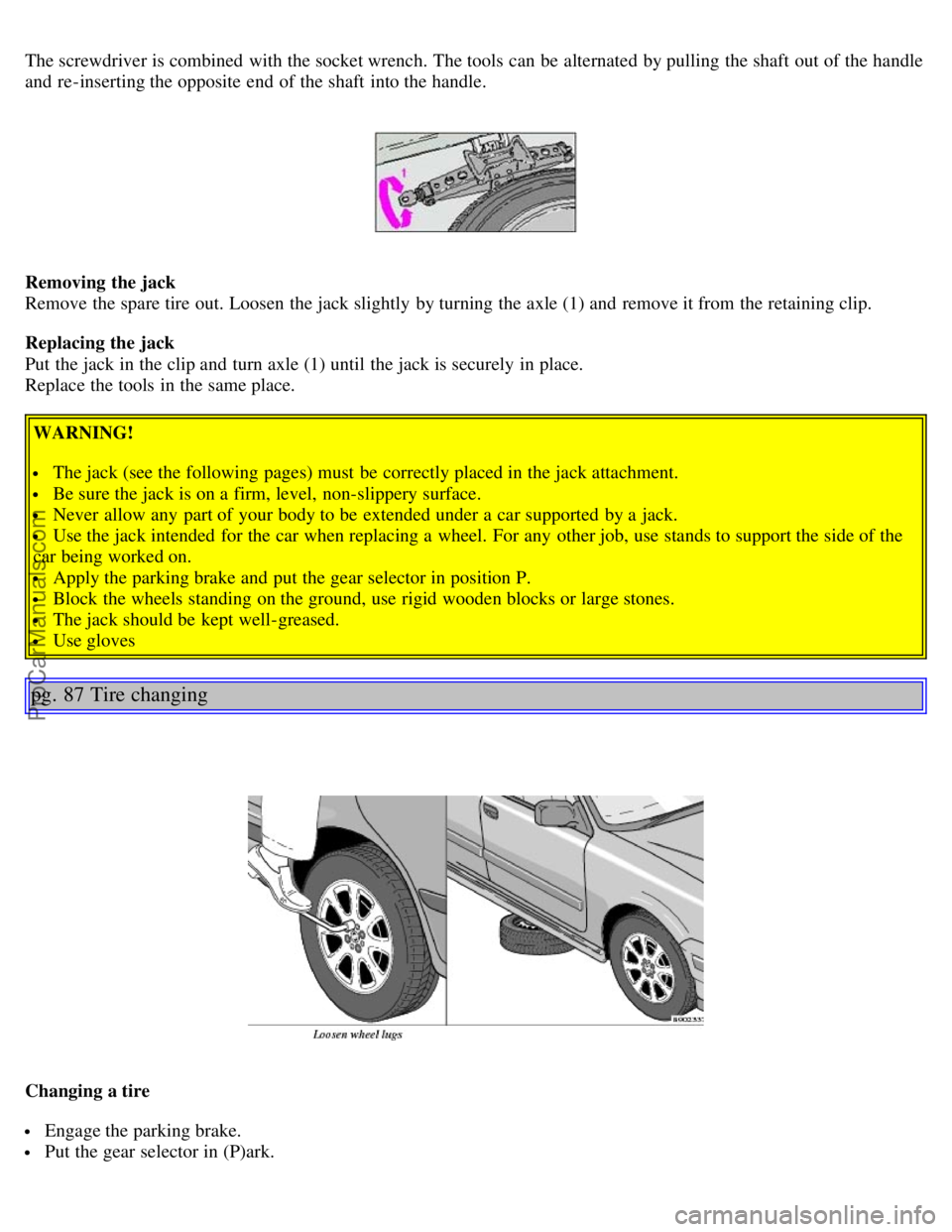
The screwdriver is combined with the socket wrench. The tools can be alternated by pulling the shaft out of the handle
and re-inserting the opposite end of the shaft into the handle.
Removing the jack
Remove the spare tire out. Loosen the jack slightly by turning the axle (1) and remove it from the retaining clip.
Replacing the jack
Put the jack in the clip and turn axle (1) until the jack is securely in place.
Replace the tools in the same place.
WARNING!
The jack (see the following pages) must be correctly placed in the jack attachment.
Be sure the jack is on a firm, level, non-slippery surface.
Never allow any part of your body to be extended under a car supported by a jack.
Use the jack intended for the car when replacing a wheel. For any other job, use stands to support the side of the
car being worked on.
Apply the parking brake and put the gear selector in position P.
Block the wheels standing on the ground, use rigid wooden blocks or large stones.
The jack should be kept well-greased.
Use gloves
pg. 87 Tire changing
Changing a tire
Engage the parking brake.
Put the gear selector in (P)ark.
ProCarManuals.com
Page 46 of 89
Install the wheel lugs and tighten handtight.
Using the lug wrench. Tighten crosswise until all lugs are snug.
Lower the vehicle to the ground and alternately tighten the lugs crosswise to 81 ft. lbs. (110 Nm).
Install the wheel cover (where applicable).
CAUTION:
Correct tightening torque on wheel lugs must be observed. The wheel lugs should never be greased or lubricated.
Extended, chromed wheel lugs must not be used with steel rims, as they make it impossible to fit the hub caps.
pg. 89 Replacing bulbs
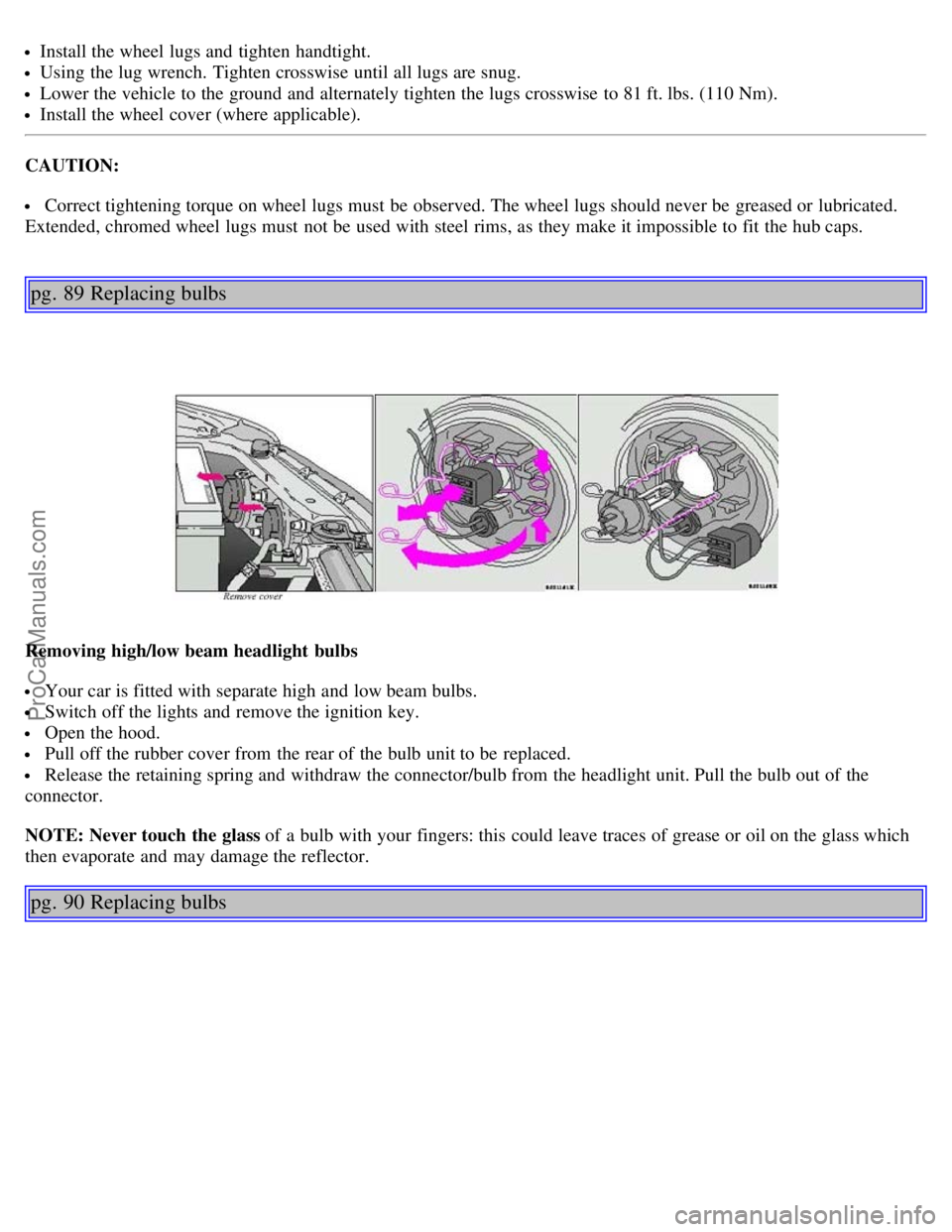
Removing high/low beam headlight bulbs
Your car is fitted with separate high and low beam bulbs.
Switch off the lights and remove the ignition key.
Open the hood.
Pull off the rubber cover from the rear of the bulb unit to be replaced.
Release the retaining spring and withdraw the connector/bulb from the headlight unit. Pull the bulb out of the
connector.
NOTE: Never touch the glass of a bulb with your fingers: this could leave traces of grease or oil on the glass which
then evaporate and may damage the reflector.
pg. 90 Replacing bulbs
ProCarManuals.com
Page 47 of 89

Installing high/low beam headlight bulbs
Insert the new bulb in the headlight unit
Reconnect the connector and wiring.
Press the retaining spring over the connector/bulb until it clicks into position.
Reinstall the rubber cover at the rear of the headlight unit.
Put the hard plastic cover in place above the headlight housing and press the tab down to secure the cover.
NOTE: Never touch the glass of a bulb with your fingers: this could leave traces of grease or oil on the glass which
then evaporate and may damage the reflector.
pg. 91 Replacing bulbs
Front direction indicators and parking lights
Removing the bulb:
Loosen the screw (A) between the headlight and direction indicator housings (max. 2 complete turns
counterclockwise), using the screwdriver supplied in the tool kit.
Press clip (D) and move the direction indicator housing forward.
With the wiring still attached, turn bulb holder slightly counterclockwise and withdraw it from the lamp housing.
Pull the bulb to remove.
ProCarManuals.com
Page 48 of 89

Replacement
Insert a new bulb in the holder.
Re-insert the bulb holder in the lamp housing and turn it clockwise until it clicks into place.
Press the lamp housing into place.
Make sure than locating pin (B) fits into the hole in the fender and slotted hole (C) around the screw.
Tighten the screw.
pg. 92 Replacing bulbs
Replacement of rear light bulbs - S40
All the bulbs in the rear light unit are replaced from inside the trunk
Procedure:
Switch off the lights and remove the ignition key.
Turn the clip 90° and pull it out. Fold the panel in the boot towards the middle so as to get access to the bulb
holders.
Push catches A and B in and remove the bulb holder. The bulbs are held in the bulb holder.
Leave the connector and cables connected to the bulb holder.
Remove the bulb by pressing it inwards and turning it a few degrees counterclockwise.
Insert a new bulb into the bulb holder and replace the holder. Check that the bulb works and refit the panel.
ProCarManuals.com
Page 49 of 89

Replacement of rear light bulbs - V40
All the bulbs in the rear light unit are replaced from inside the cargo area.
Procedure:
Switch off the lights and remove the ignition key.
Open the cover in the panel
Push catches A and B in and remove the bulb holder. The bulbs are held in the bulb holder.
Leave the connector and cables connected to the bulb holder.
Remove the bulb by pressing it inwards and turning it a few degrees counterclockwise.
Insert a new bulb into the bulb holder and replace the holder. Check that the bulb works and refit the cover.
1 Tail light (rear parking light) 5W
2 Direction indicator 21W
3 Brake light 21W
4 Tail light 5W
5 Backup light 21W
6 Rear fog light (Left side only) 21W
pg. 93 Replacing bulbs
Side direction indicator
1. Slide the lens forward and pull out the rear edge.
2. Pull out the entire lens/bulb unit.
3. With the lens toward you, turn the bulb holder 1/4 turn (the wires should not be disconnected from the holder) and
pull out the bulb holder from the lens unit.
4. Pull the old bulb straight out and press a new one into place.
5. Replace the entire unit in the reverse order.
ProCarManuals.com
Page 50 of 89
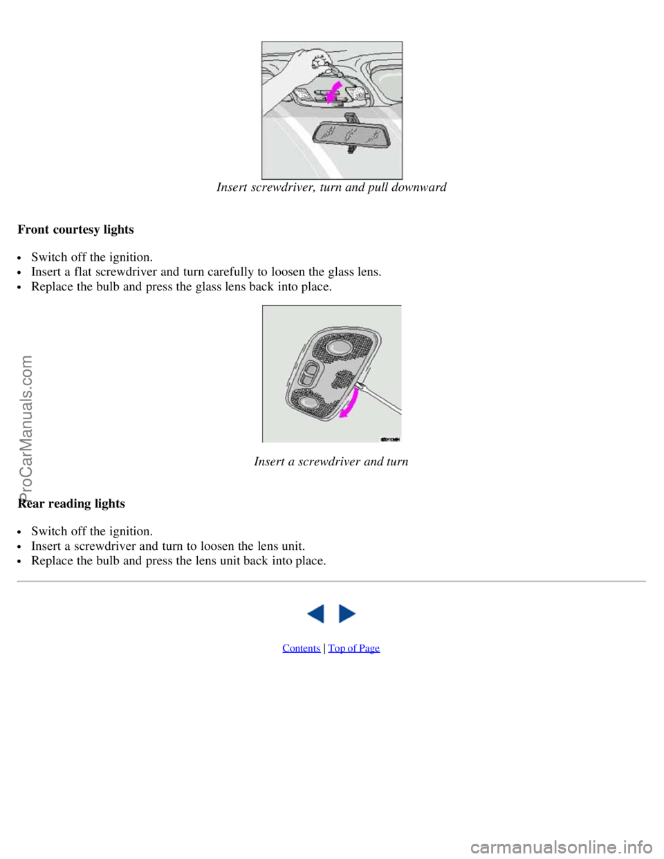
Insert screwdriver, turn and pull downward
Front courtesy lights
Switch off the ignition.
Insert a flat screwdriver and turn carefully to loosen the glass lens.
Replace the bulb and press the glass lens back into place.
Insert a screwdriver and turn
Rear reading lights
Switch off the ignition.
Insert a screwdriver and turn to loosen the lens unit.
Replace the bulb and press the lens unit back into place.
Contents | Top of Page
ProCarManuals.com
Page 52 of 89

If the stone chip has not penetrated down to the metal and an undamaged layer of paint remains, the touchup paint can
be applied as soon as the spot has been cleaned.
Deep scratches
1. Place a strip of masking tape over the damaged surface. Pull the tape off so that any loose flakes of paint adhere to
it.
2. Thoroughly mix the primer and apply it with a small brush.
When the primer surface is dry, the paint can be applied using a brush. Mix the paint thoroughly; apply several thin
paint coats and let dry after each application.
3. If there is a longer scratch, you may want to protect surrounding paint by masking it off.
pg. 103 Washing
Washing the car
The car should be washed at regular intervals since dirt, dust, insects and tar spots adhere to the paint and may cause
damage.
NOTE: It is particularly important to wash the car frequently in the wintertime to prevent corrosion, when salt has
been used on the roads.
When washing the car, do not expose it to direct sunlight. Use lukewarm water to soften the dirt before you wash
with a sponge, and plenty of water, to avoid scratching.
Bird droppings: Remove from paintwork as soon as possible. Otherwise the finish may be permanently damaged.
A detergent can be used to facilitate the softening of dirt and oil.
A water-soluble grease solvent may be used in cases of sticky dirt. However, use a wash place equipped with a
drainage separator.
Dry the car with a clean chamois and remember to clean the drain holes in the doors and rocker panels.
The power radio antenna (sedans) must be dried after washing.
Tar spots can be removed with kerosene or tar remover after the car has been washed.
A stiff-bristle brush and lukewarm soapy water can be used to clean the wiper blades. Frequent cleaning improves
visibility considerably.
Wash off the dirt from the underside (wheel housings fenders, etc.).
In areas of high industrial fallout, more frequent washing is recommended.
CAUTION: During high pressure washing, the spray nozzle must never be closer to the vehicle than 13" (30 cm). Do
not spray into the locks.
When washing or steam cleaning the engine, avoid spraying water or steam directly on the electrical components or
ProCarManuals.com
Page 58 of 89
The fuel filter should be replaced at 105,000 miles (168,000 km). The filter is replaced as a complete unit. Replace
more frequently if contaminated fuel is introduced into the tank, or if there is reason to suspect that this has occurred.
Fuel system, including filler cap, tank, lines and connections
The ability of the fuel system to contain hydrocarbons depends upon a leak-free system. Inspect fuel lines every
30,000 miles (48,000 km). Check for proper sealing of the fuel filler cap which contains "O" ring seals.
NOTE: If the fuel filler cap is not closed tightly or if the engine is running when the car is refueled, the Check Engine
light (Malfunction indicator) may indicate a fault. However, your vehicle's performance will not be affected. Use only
Volvo original or approved fuel filler caps.
Timing belt
For proper functioning of the vehicle and its emission control systems, the timing belt and belt tensioner must be
replaced every 105,000 miles (168,000 km). Engine damage will occur if the belt fails.
PCV system
(on turbocharged models)
The nipple in the intake manifold and the filter at the end of the PCV hose in the air cleaner should be inspected and
cleaned at 105,000 miles (168,000 km) and thereafter, again at 150,000 mile (240,000 km) intervals.
Spark plugs
The spark plugs should be replaced every 45,000 miles (72,000 km) under normal driving conditions. City driving or
fast highway driving may necessitate replacement sooner.
Under normal driving conditions, spark plugs require no maintenance between replacement intervals. When installing
new plugs, be sure to use the right type and to tighten them correctly. When changing the plugs, clean the terminals
and rubber seals. Also check that the suppressor connectors are in good condition. Cracked or damaged connectors
should be replaced.
pg. 111 Engine compartment
Engine compartment S40/V40
1 Power brakes
2 Brake fluid reservoir
3 Fuse box
4 Engine air cleaner
5 Battery
7 Radiator
8 Oil filter
10 Engine oil dipstick
11 Generator
12 Windshield/headlight washer fluid reservoir
13 Power steering pump
14 Power steering fluid reservoir
15 Engine oil filler cap
16 Coolant expansion tank
17 Windshield wiper motor
18 Chassis number
A ABS
B Air conditioning compressor
C Air conditioning condenser
ProCarManuals.com
Page 59 of 89

D Air conditioning accumulator
WARNING!
The coolant fan may start or continue to operate (for up to 6 minutes) after the engine has been switched off.
pg. 112 Fuel/emissions systems
Fuel system
The fuel system is all-electronic and is microprocessor-controlled. It can continually compensate for variation in
engine load, speed and temperature to give the best economy and power. A mass air flow sensor measures the inducted
air. In this way the system can make instantaneous adjustments for changes in air temperature or density, thus always
assuring the best economy with the lowest possible exhaust emissions.
Heated oxygen sensor
This is an emission control system designed to reduce emissions and improve fuel economy. The heated oxygen sensor
monitors the composition of the exhaust gases leaving the engine. The exhaust gas analysis is fed into an electronic
module. This adjusts the air-fuel ratio to provide optimum conditions for combustion and efficient reduction of the
three major pollutants (hydrocarbons, carbon monoxide and oxides of nitrogen (NOx) by a three-way catalytic
converter.
Crankcase ventilation
The engine is provided with positive crankcase ventilation which prevents crankcase gases from being released into the
atmosphere. Instead, the crankcase gases are admitted to the intake manifold and cylinders.
Evaporative control system
The car is equipped with an evaporative control system which prevents gasoline vapor from being released into the
atmosphere.
The system consists of a fuel tank with filler pipe and cap, a rollover valve, a Fill Limit Vent Valve (FLVV), vapor
vent lines, a charcoal canister, a purge line, a purge control valve and engine connections. In addition, there is a
pressure sensor connected to the fuel tank and a filter -protected Canister Close Valve (CCV) on the atmospheric side
of the canister, for system diagnosis.
The gasoline vapor is channeled through the rollover valve and the FLVV via the vapor vent lines into the charcoal
canister, where it is stored. When the engine is started, the gasoline vapor is drawn from the charcoal canister to the
engine's air intake system and into the combustion process.
NOTE:
If the fuel filler cap is not closed tightly or if the engine is running when the car is refueled, the Check Engine light
ProCarManuals.com