run flat VOLVO V60 2014 Owners Manual
[x] Cancel search | Manufacturer: VOLVO, Model Year: 2014, Model line: V60, Model: VOLVO V60 2014Pages: 442, PDF Size: 13.85 MB
Page 280 of 442
08 Starting and driving
08
278
Gear selector inhibitor
There are two different types of gear selector inhibitor - mechanical and automatic.
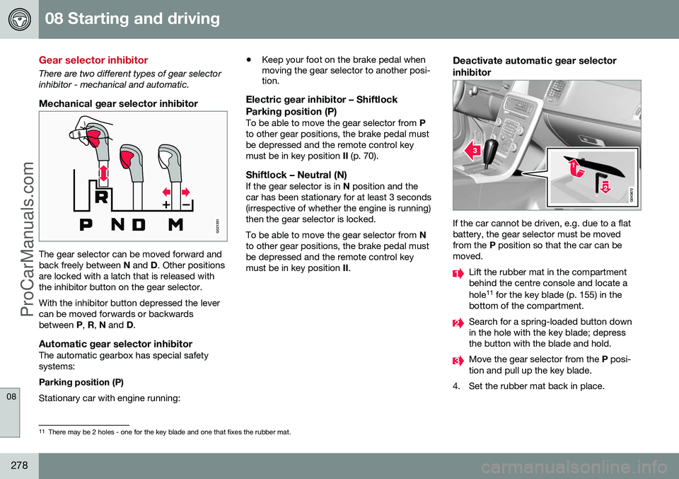
Mechanical gear selector inhibitor
G021351
The gear selector can be moved forward and back freely between N and D. Other positions
are locked with a latch that is released withthe inhibitor button on the gear selector. With the inhibitor button depressed the lever can be moved forwards or backwardsbetween P, R , N and D.
Automatic gear selector inhibitorThe automatic gearbox has special safetysystems: Parking position (P) Stationary car with engine running: •
Keep your foot on the brake pedal when moving the gear selector to another posi-tion.
Electric gear inhibitor – Shiftlock
Parking position (P)
To be able to move the gear selector from P
to other gear positions, the brake pedal must be depressed and the remote control keymust be in key position II (p. 70).
Shiftlock – Neutral (N)If the gear selector is in N position and the
car has been stationary for at least 3 seconds(irrespective of whether the engine is running)then the gear selector is locked. To be able to move the gear selector from N
to other gear positions, the brake pedal must be depressed and the remote control keymust be in key position II.
Deactivate automatic gear selector inhibitor
If the car cannot be driven, e.g. due to a flat battery, the gear selector must be movedfrom the P position so that the car can be
moved.
Lift the rubber mat in the compartment behind the centre console and locate a hole 11
for the key blade (p. 155) in the
bottom of the compartment.
Search for a spring-loaded button down in the hole with the key blade; depressthe button with the blade and hold.
Move the gear selector from the P posi-
tion and pull up the key blade.
4. Set the rubber mat back in place.
11 There may be 2 holes - one for the key blade and one that fixes the rubber mat.
ProCarManuals.co’
Page 332 of 442
09 Wheels and tyres
09
330* Option/accessory, for more information, see Introduction.
Tyre pressure monitoring*
Tyre pressure monitoring (TPMS) (Tyre Pressure Monitoring System) 3
warns the
driver when the pressure is too low in one or more of the car's tyres. Tyre pressure monitoring uses sensors located inside the air valve in each wheel.When the car is driven at about 40 km/h thesystem detects the tyre pressure. If the pres- sure is too low then a warning lamp
in the
combined instrument panel illuminates and a message is shown in the information display. Both factory-fitted and optional wheels can be equipped with TPMS sensors in thevalves. If wheels without TPMS sensors are used or if a sensor has failed then
Tyre press. syst
Service required will be shown.
Always check the system after changing a wheel in order to ensure that replacementwheels work with the system. For information on the correct tyre pressure, see Tyres - air pressure (p. 328). The system does not replace normal tyre maintenance.
IMPORTANT
If a fault should arise in the tyre pressure system a warning lamp
in the com-
bined instrument panel will illuminate and a message will be shown. This can be forvarious reasons, e.g. fitting a wheel notequipped with a sensor adapted for Vol-vo's tyre pressure monitoring system.
Related information
• Tyre pressure monitoring* - adjust (recali- bration) (p. 330)
• Tyre pressure monitoring* - rectifying lowtyre pressure (p. 331)
• Tyre pressure monitoring* - activate/deactivate (p. 331)
• Tyre pressure monitoring* - recommenda-tions (p. 332)
• Tyre pressure monitoring - driveablepunctured tyres* (p. 332)
Tyre pressure monitoring* - adjust (recalibration)
Tyre pressure monitoring (TPMS) (Tyre Pressure Monitoring System) 4
warns the
driver when the pressure is too low in one or more of the car's tyres. TPMS can be adjusted in order to follow Vol- vo's tyre pressure recommendations (p. 328),when driving with a heavy load for example.
NOTE
The engine must not be running when the tyres are calibrated.
The settings are made with the control in the centre console, see MY CAR (p. 103).
1. Inflate the tyres to the required pressure and select key position I or II.
2. Select the menu system MY CAR to open
the menus for tyre pressure.
3. Select
Calibrate tyre pressure.
4. Press OK.
5. Start the car and drive at least at 40 km/h for a total of at least 1 minute and check that the message disappears.
> Then the TPMS is recalibrated to thenew tyre pressure.
3Option only in certain markets.
4 Option only in certain markets.
ProCarManuals.co’
Page 333 of 442
09 Wheels and tyres
09
* Option/accessory, for more information, see Introduction.331
Related information
• Tyre pressure monitoring* (p. 330)
• Tyres - air pressure (p. 328)
Tyre pressure monitoring* - rectifying low tyre pressure
Tyre pressure monitoring TPMS (Tyre Pressure Monitoring System) 5
warns the
driver when the pressure is too low in one or more of the car's tyres. If a message for low tyre pressure is shown in the display:
1. Check the tyre pressure in all four tyres.
2. Inflate the tyre(s) to the correct pressure.
3. Drive at least at 40 km/h for a total of at least 1 minute and check that the mes- sage disappears.
Related information
• Tyre pressure monitoring* (p. 330)
Tyre pressure monitoring* - activate/ deactivate
Tyre pressure monitoring (TPMS) (Tyre Pressure Monitoring System) 6
warns the
driver when the pressure is too low in one or more of the car's tyres.
NOTE
The engine must not be running when tyre pressure monitoring is activated/deacti-vated.
The settings are made with the control in the centre console, see MY CAR (p. 103).
1. Select key position I or II.
2. Select the system MY CAR to open the
menus for tyre pressure.
3. Select Tyre pressure system/Pressure monitoring and press OK.
> An
X is shown in the information dis-
play if the system is activated, the option disappears if the system isdeactivated.
Related information
• Tyre pressure monitoring* (p. 330)
5
Option only in certain markets.
6 Option only in certain markets.
ProCarManuals.co’
Page 334 of 442

09 Wheels and tyres
09
332* Option/accessory, for more information, see Introduction.
Tyre pressure monitoring* - recommendations
Tyre pressure monitoring TPMS (Tyre Pressure Monitoring System) 7
warns the
driver when the pressure is too low in one or more of the car's tyres.
• Volvo recommends that TPMS sensors are fitted to all wheels on the car.
• Volvo recommends that sensors are notmoved between different wheels.
WARNING
When inflating a tyre equipped with TPMS, hold the nozzle of the pump directlyagainst the valve to avoid damaging thevalve.
Related information
• Tyre pressure monitoring* (p. 330)
Tyre pressure monitoring - driveable punctured tyres*
If SST (Self Supporting run flat Tires)* is selected, the car is also equipped with TPMS(p. 330). This type of tyre has a specially reinforced side wall that makes continued driving possi-ble to a limited extent despite the tyre losingall or some of its pressure. These tyres are fit-ted on a special rim. (Normal tyres can alsobe fitted to this rim.) If an SST tyre loses tyre pressure then the yellow TPMS lamp in the combined instru-ment panel illuminates and a message isshown in the information display. If thisoccurs, reduce speed to max. 80 km/h. Thetyre must be replaced as soon as possible. Drive carefully, in some cases it can be diffi- cult to see which tyre is faulty. In order toestablish which tyre needs attention, checkall four tyres.
WARNING
Only people with knowledge of SST tyres should fit them. SST tyres must only be fitted together with TPMS. After an error message about low tyre pressure has been shown, do not drivefaster than 80 km/h. Maximum mileage before tyre replacement is 80 km. Avoid hard driving such as sudden braking or turning. SST tyres must be replaced if they are damaged or punctured.
Related information
•Tyre pressure monitoring* (p. 330)
7
Option only in certain markets.
ProCarManuals.co’
Page 338 of 442
||
09 Wheels and tyres
09
336
7. Flick the switch to position I.
WARNING
Never stand next to the tyre when the compressor is running. If cracks orunevenness arise then the compressormust be switched off immediately. Thejourney should not be continued. Contact-ing an authorised tyre centre is recom-mended.
NOTE
When the compressor starts, the pressure can increase up to 6 bar but the pressuredrops after approximately 30 seconds.
8. Inflate the tyre for 7 minutes.
IMPORTANT
Risk of overheating. The compressor must not run for more than 10 minutes.
9. Switch off the compressor to check the
pressure on the pressure gauge. Mini- mum pressure is 1.8 bar and maximum3.5 bar. (Release air with the pressurereducing valve if the tyre pressure is toohigh.)
WARNING
If the pressure is below 1.8 bar then the hole in the tyre is too big. The journeyshould not be continued. Contacting anauthorised tyre centre is recommended.
10. Switch off the compressor and unplug thecable from the 12 V socket.
11. Detach the hose from the tyre valve and fit the valve cap.
12. As soon as possible, drive approximately 3 km at a maximum speed of 80 km/h so that the sealing fluid can seal the tyre.
Related information
• Emergency puncture repair (p. 333)
• Emergency puncture repair - rechecking (p. 336)
• Emergency puncture repair kit - overview(p. 334)
Emergency puncture repair - rechecking
Emergency puncture repair, where the emer- gency puncture repair kit (TMK - TemporaryMobility Kit) is used to seal a puncture andcheck and adjust the tyre pressure (p. 407).
Check tyre pressure1. Reconnect the equipment.
2. Read the tyre pressure on the pressure
gauge.
• If it is below 1.3 bar 8
then the tyre is
insufficiently sealed. The journey should not be continued. Contact atyre centre.
• If the tyre pressure is higher than 1.3 bar 8
, the tyre must be inflated to the
pressure specified in accordance with the tyre pressure table, see Tyres -approved tyre pressures (p. 407).Release air using the pressure reduc-ing valve if the tyre pressure is toohigh.
8 1 bar = 100 kPa.
ProCarManuals.co’
Page 339 of 442
09 Wheels and tyres
09
337
WARNING
Do not unscrew the bottle, it is equipped with a reverse catch to prevent leakage.
3. Make sure the compressor is switchedoff. Detach the air hose and cable. Fit the valve cap.
NOTE
•After a tyre has been inflated, always refit the dust cap in order to avoiddamage to the valve from gravel, dirt,etc.
• Only use plastic dust caps. Metal dustcaps can rust and become difficult tounscrew.
NOTE
The sealing fluid bottle and the hose must be replaced after use. Volvo recommendsthat this replacement is performed by anauthorised Volvo workshop.
WARNING
Check the tyre pressure regularly.
Volvo recommends that you drive to the near- est authorised Volvo workshop for thereplacement/repair of the damaged tyre. Advise the workshop that the tyre containssealing fluid.
WARNING
You should not drive faster than 80 km/h after the emergency tyre repair kit hasbeen used. Volvo recommends that youvisit an authorised Volvo workshop forinspection of the sealed tyre (maximumdriving distance is 200 km). The staff therecan determine whether or not the tyre canbe repaired or if it needs to be replaced.
Related information
•
Emergency puncture repair (p. 333)
• Emergency puncture repair - operation (p. 335)
• Emergency puncture repair kit - overview(p. 334)
Emergency puncture repair kit - inflating the tyres
The car's original tyres can be inflated using the compressor in the emergency puncturerepair kit (p. 334).
1. The compressor must be switched off.
Make sure that the switch is in position 0
and locate the cable and air hose.
2. Unscrew the wheel's dust cap and screw in the air hose valve connection to the bottom of the thread on the tyre's airvalve.
WARNING
Inhaling car exhaust fumes could result in danger to life. Never leave the engine run-ning in sealed areas or areas that lack suf-ficient ventilation.
WARNING
Do not leave children in the car without supervision when the engine is running.
3. Connect the cable to one of the car's 12 V sockets and start the car.
4. Start the compressor by flicking the switch to position I.
ProCarManuals.co’
Page 340 of 442
||
09 Wheels and tyres
09
338
IMPORTANT
Risk of overheating. The compressor must not run for more than 10 minutes.
5. Inflate the tyre to the pressure specified inaccordance with the tyre pressure table, Tyres - approved tyre pressures (p. 407).Release air using the pressure reducingvalve if the tyre pressure is too high.
6. Switch off the compressor Detach the air hose and cable.
7. Refit the dust cap.
Related information
• Emergency puncture repair (p. 333)
• Emergency puncture repair kit - overview (p. 334)
• Emergency puncture repair - rechecking(p. 336)
Emergency puncture repair kit - sealant
The container (bottle) with the emergency puncture repair kit (p. 334) contains sealantand it can be replaced. Replace the bottle when the expiration date has passed. Treat the old bottle as environ-mentally hazardous waste.
WARNING
The bottle contains 1.2-Ethanol and natu- ral rubber-latex. Harmful if ingested. Could result in allergic reaction in the event of skin contact. Avoid contact with the skin and eyes.Store out of the reach of children.
Related information
•
Emergency puncture repair (p. 333)
ProCarManuals.co’
Page 438 of 442
12 Alphabetical Index
12
436
Seats.......................................................... 72head restraints, rear.............................. 74
heating................................................ 122
Heating............................................... 122
lowering the front backrest................... 72
lowering the rear backrest.................... 75
power.................................................... 73
Self Supporting run flat Tyres (SST)........ 332
Sensus....................................................... 68
Service position....................................... 359
Service programme................................. 340
Set time interval....................................... 202
Side airbag SIPS.................................. 31, 36
SIPS airbag................................................ 31
Skidding................................................... 299
slippery driving conditions....................... 299
Soot filter................................................. 305
SOOT FILTER FULL................................. 305
spare wheel............................................. 324 installation........................................... 327
Speed limiter............................................ 182 alarm for speed exceeded.................. 184
deactivation........................................ 184
getting started............................ 182, 183
temporary deactivation....................... 183
Speed ratings, tyres................................. 323 Spin control............................................. 175
Stability and traction control system 175, 178
operation............................................. 176
Stability system....................................... 175
Stains....................................................... 381
Start/Stop................................................ 279 Function and operation...................... 280
the engine does not stop.................... 282
Steering force, speed related.................. 257
Steering force level, see Steering force... 257
Steering lock............................................ 265
Steering wheel........................................... 76 heating.................................................. 77
keypad.................................................. 77
paddle................................................... 77
steering wheel adjustment.................... 76
Stone chips and scratches...................... 383 Storage spaces glovebox............................................. 140
Jacket holder...................................... 139
tunnel console.................................... 139
Storage spaces in the passenger com-
partment.................................................. 137 Sunroof opening and closing............................. 98
pinch protection.................................. 100 sunscreen............................................. 99
ventilation position................................ 99
Sunscreen, sunroof.................................... 99
Switching off the engine.......................... 265Symbols indicator symbols..................... 60, 62, 64
warning symbols............................. 60, 62
Symbols and messages Adaptive Cruise Control..................... 200Collision Warning with Auto
Brake.......................................... 211, 222
Driver Alert Control............................. 227
Lane Departure Warning..................... 232
LKA..................................................... 238
System tripping.................................................. 36
T
Tailgate Locking/unlocking.............................. 167
Temperature actual temperature............................. 116
Temperature control................................ 124
Tools........................................................ 320
Total airing function......................... 115, 166
ProCarManuals.co’