low beam VOLVO V60 2017 Owner´s Manual
[x] Cancel search | Manufacturer: VOLVO, Model Year: 2017, Model line: V60, Model: VOLVO V60 2017Pages: 406, PDF Size: 9.65 MB
Page 103 of 406
INSTRUMENTS AND CONTROLS
}}
* Option/accessory, for more information, see Introduction.101
Rain sensor*
The rain sensor automatically regulates wiper speed according to the amount of water on thewindshield.
The sensitivity of the rain sensor can be adjusted moving the thumb wheel up (the wipers willsweep the windshield more frequently) or down(the wipers will sweep the windshield less fre-quently).
NOTE
The wipers will make an extra sweep each time the thumb wheel is adjusted upward.
When the rain sensor is activated, the symbol
will illuminate in the instrument panel.
Activating and setting the sensitivity
When activating the rain sensor, the vehicle must be running or in ignition mode II and the wind-
shield wiper lever must be in position 0 or in the
single sweep position. Activate the rain sensor by pressing the button
. The windshield wipers will make one
sweep. Press the lever up for the wipers to make an extra sweep. The rain sensor returns to activemode when the stalk is released back to position 0 .
Deactivating
Deactivate the rain sensor by pressing the button
or press the lever down to another wiper
position. The rain sensor is automatically deactivated when the key is removed from the ignition slot or fiveminutes after the ignition has been switched off.
CAUTION
The rain sensor should be deactivated when washing the car in an automatic car wash, etc.If the rain sensor function is left on, the wip-ers will start inadvertently in the car wash andcould be damaged.
Windshield washer
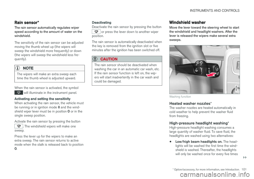
Move the lever toward the steering wheel to start the windshield and headlight washers. After thelever is released the wipers make several extrasweeps.
Washing function
Heated washer nozzles *The washer nozzles are heated automatically in cold weather to help prevent the washer fluidfrom freezing.
High-pressure headlight washing *High-pressure headlight washing consumes alarge quantity of washer fluid. To save fluid, theheadlights are washed using two alternatives:
• Low/high beam headlights on.
The head-
lights will be washed the first time the wind-shield is washed. Thereafter, the headlightswill only be washed once for every five times
Page 209 of 406
DRIVER SUPPORT
}}
207
City Safety – Laser sensor
The laser sensor
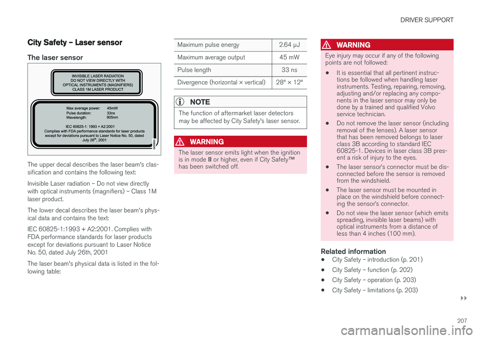
The upper decal describes the laser beam's clas- sification and contains the following text: Invisible Laser radiation – Do not view directly with optical instruments (magnifiers) – Class 1Mlaser product. The lower decal describes the laser beam's phys- ical data and contains the text: IEC 60825-1:1993 + A2:2001. Complies with FDA performance standards for laser productsexcept for deviations pursuant to Laser NoticeNo. 50, dated July 26th, 2001 The laser beam's physical data is listed in the fol- lowing table:
Maximum pulse energy2.64 μJ
Maximum average output45 mW
Pulse length33 ns
Divergence (horizontal × vertical)28° × 12°
NOTE
The function of aftermarket laser detectors may be affected by City Safety's laser sensor.
WARNING
The laser sensor emits light when the ignition is in mode II or higher, even if City Safety ™
has been switched off.
WARNING
Eye injury may occur if any of the following points are not followed:
• It is essential that all pertinent instruc-tions be followed when handling laserinstruments. Testing, repairing, removing,adjusting and/or replacing any compo-nents in the laser sensor may only bedone by a trained and qualified Volvoservice technician.
• Do not remove the laser sensor (includingremoval of the lenses). A laser sensorthat has been removed belongs to laserclass 3B according to standard IEC60825-1. Devices in laser class 3B pres-ent a risk of injury to the eyes.
• The laser sensor
Page 287 of 406
STARTING AND DRIVING
285
Conserving electrical current
Keep the following in mind to help minimize bat- tery drain:
• When the engine is not running, avoid using ignition mode
II. Many electrical systems (the
audio system, the optional navigation system, power windows, etc) will function in ignition modes 0 and I. These modes reduce drain
on the battery.
• Please keep in mind that using systems, accessories, etc., that consume a great dealof current when the engine is not runningcould result in the battery being completelydrained. Driving or having the engine runningfor approximately 15 minutes will help keepthe battery charged.
• The optional 12-volt socket in the cargoarea (p. 143) area provides electrical currenteven with the ignition switched off, whichdrains the battery.
Before a long distance trip
It is always worthwhile to have your vehicle checked by a trained and qualified Volvo servicetechnician before driving long distances. Yourretailer will also be able to supply you with bulbs,fuses, spark plugs and wiper blades for your usein the event that problems occur.
As a minimum, the following items should be checked before any long trip:
• Check that engine runs smoothly and thatfuel consumption is normal.
• Check for fuel, oil, and fluid leakage.
• Have the transmission oil level checked.
• Check condition of drive belts.
• Check state of the battery's charge.
• Examine tires carefully (the spare tire aswell), and replace those that areworn (p. 302). Check tire pressure (p. 309).
• The brakes, front wheel alignment, and steer-ing gear should be checked by a trained andqualified Volvo service technician only.
• Check all lights, including high beams.
• Reflective warning triangles are legallyrequired in some states/provinces.
• Have a word with a trained and qualifiedVolvo service technician if you intend to drivein countries where it may be difficult toobtain the correct fuel. •
Consider your destination. If you will be driv-ing through an area where snow or ice arelikely to occur, consider snow tires (p. 316).
Related information
•
Changing a wheel – removing wheel (p. 303)
• Bulbs – introduction (p. 344)
Page 348 of 406
||
MAINTENANCE AND SERVICING
3462. Reinstall the headlight housing and locking
pins. The short locking pin should be closest to the grille. Check that they are correctlyinserted. The headlight housing must be properly in place and the wiring connector correctlyreconnected before the lighting is switchedon or the remote key is inserted into the igni-tion slot.
3. Check that the lights function properly.
Related information
• Bulbs – introduction (p. 344)
• Bulbs – cover (p. 346)
• Bulbs – specifications (p. 351)
Bulbs – cover The larger cover has to be removed in order to change the high/low beam headlight bulbs.
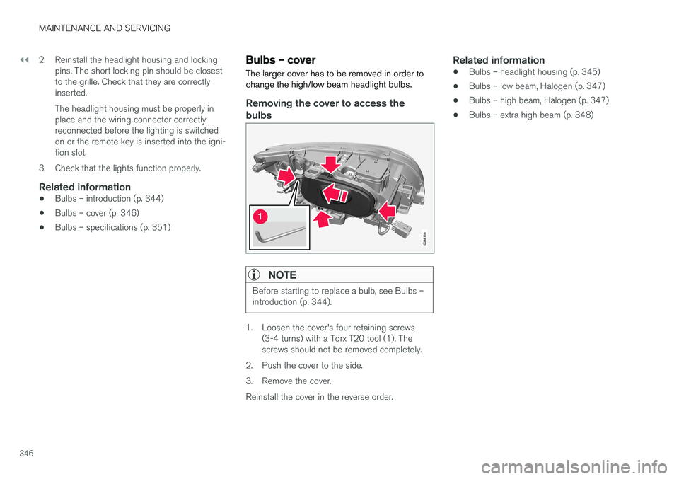
Removing the cover to access the
bulbs
NOTE
Before starting to replace a bulb, see Bulbs – introduction (p. 344).
1. Loosen the cover's four retaining screws (3-4 turns) with a Torx T20 tool (1). The screws should not be removed completely.
2. Push the cover to the side.
3. Remove the cover.Reinstall the cover in the reverse order.
Related information
• Bulbs – headlight housing (p. 345)
• Bulbs – low beam, Halogen (p. 347)
• Bulbs – high beam, Halogen (p. 347)
• Bulbs – extra high beam (p. 348)
Page 349 of 406
MAINTENANCE AND SERVICING
347
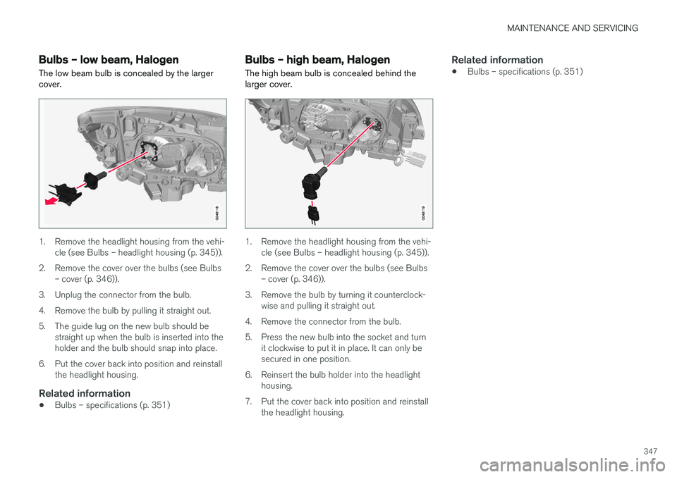
Bulbs – low beam, Halogen The low beam bulb is concealed by the larger cover.
1. Remove the headlight housing from the vehi-cle (see Bulbs – headlight housing (p. 345)).
2. Remove the cover over the bulbs (see Bulbs – cover (p. 346)).
3. Unplug the connector from the bulb.
4. Remove the bulb by pulling it straight out.
5. The guide lug on the new bulb should be straight up when the bulb is inserted into the holder and the bulb should snap into place.
6. Put the cover back into position and reinstall the headlight housing.
Related information
• Bulbs – specifications (p. 351)
Bulbs – high beam, Halogen
The high beam bulb is concealed behind the larger cover.
1. Remove the headlight housing from the vehi- cle (see Bulbs – headlight housing (p. 345)).
2. Remove the cover over the bulbs (see Bulbs – cover (p. 346)).
3. Remove the bulb by turning it counterclock- wise and pulling it straight out.
4. Remove the connector from the bulb.
5. Press the new bulb into the socket and turn it clockwise to put it in place. It can only be secured in one position.
6. Reinsert the bulb holder into the headlight housing.
7. Put the cover back into position and reinstall the headlight housing.
Related information
• Bulbs – specifications (p. 351)
Page 353 of 406
MAINTENANCE AND SERVICING
}}
* Option/accessory, for more information, see Introduction.351
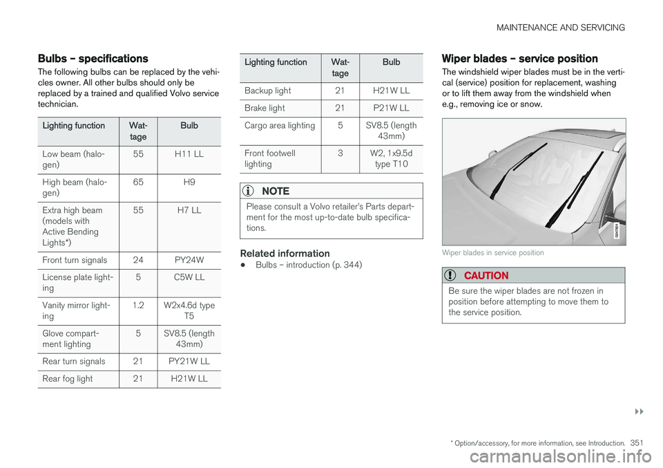
Bulbs – specifications The following bulbs can be replaced by the vehi- cles owner. All other bulbs should only bereplaced by a trained and qualified Volvo servicetechnician.
Lighting functionWat-
tageBulb
Low beam (halo- gen)55H11 LL
High beam (halo- gen)65H9
Extra high beam (models withActive Bending Lights *)55H7 LL
Front turn signals24PY24W
License plate light- ing5C5W LL
Vanity mirror light- ing1.2W2x4.6d type
T5
Glove compart- ment lighting5SV8.5 (length43mm)
Rear turn signals21PY21W LL
Rear fog light21H21W LL
Lighting functionWat-
tageBulb
Backup light21H21W LL
Brake light21P21W LL
Cargo area lighting5SV8.5 (length 43mm)
Front footwell lighting3W2, 1x9.5dtype T10
NOTE
Please consult a Volvo retailer
Page 394 of 406
||
SPECIFICATIONS
* Option/accessory, for more information, see Introduction.
392
Symbols in the main instrument panel
Warning symbols in the instrument panel
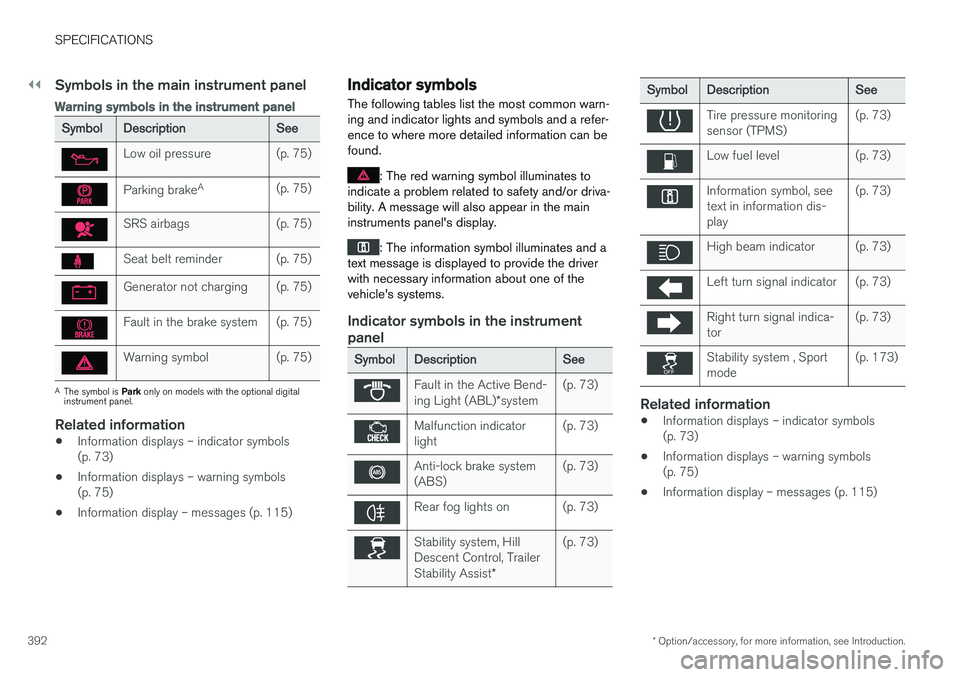
SymbolDescriptionSee
Low oil pressure(p. 75)
Parking brake A(p. 75)
SRS airbags(p. 75)
Seat belt reminder(p. 75)
Generator not charging(p. 75)
Fault in the brake system(p. 75)
Warning symbol(p. 75)
A
The symbol is Park only on models with the optional digital
instrument panel.
Related information
• Information displays – indicator symbols (p. 73)
• Information displays – warning symbols(p. 75)
• Information display – messages (p. 115)
Indicator symbols
The following tables list the most common warn- ing and indicator lights and symbols and a refer-ence to where more detailed information can befound.
: The red warning symbol illuminates to
indicate a problem related to safety and/or driva- bility. A message will also appear in the maininstruments panel's display.
: The information symbol illuminates and a
text message is displayed to provide the driver with necessary information about one of thevehicle's systems.
Indicator symbols in the instrument panel
SymbolDescriptionSee
Fault in the Active Bend- ing Light (ABL) *system(p. 73)
Malfunction indicator light(p. 73)
Anti-lock brake system (ABS)(p. 73)
Rear fog lights on(p. 73)
Stability system, Hill Descent Control, Trailer Stability Assist *(p. 73)
SymbolDescriptionSee
Tire pressure monitoring sensor (TPMS)(p. 73)
Low fuel level(p. 73)
Information symbol, see text in information dis-play(p. 73)
High beam indicator(p. 73)
Left turn signal indicator(p. 73)
Right turn signal indica- tor(p. 73)
Stability system , Sport mode(p. 173)
Related information
•Information displays – indicator symbols (p. 73)
• Information displays – warning symbols(p. 75)
• Information display – messages (p. 115)
Page 395 of 406
SPECIFICATIONS
* Option/accessory, for more information, see Introduction.393
Information symbols
The following tables list the most common warn- ing and indicator lights and symbols and a refer-ence to where more detailed information can befound.
: The red warning symbol illuminates to
indicate a problem related to safety and/or driva- bility. A message will also appear in the maininstruments panel's display.
: The information symbol illuminates and a
text message is displayed to provide the driver with necessary information about one of thevehicle's systems.
Information symbols in the instrument panel
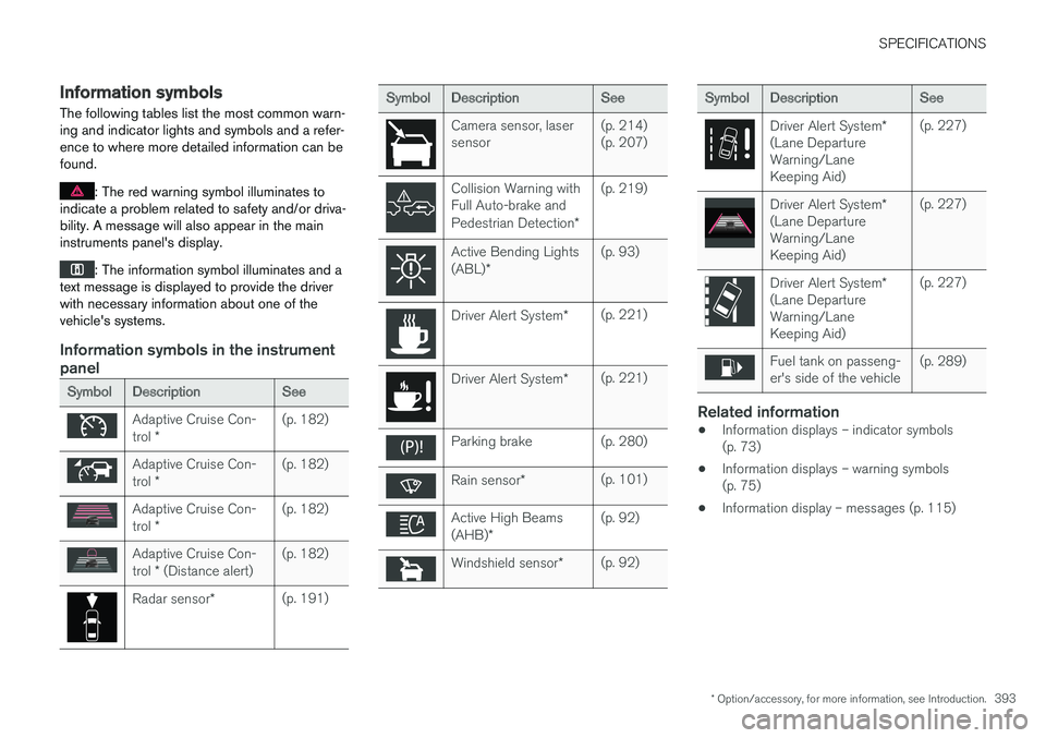
SymbolDescriptionSee
Adaptive Cruise Con- trol *(p. 182)
Adaptive Cruise Con- trol *(p. 182)
Adaptive Cruise Con- trol *(p. 182)
Adaptive Cruise Con- trol * (Distance alert)(p. 182)
Radar sensor *(p. 191)
SymbolDescriptionSee
Camera sensor, laser sensor(p. 214) (p. 207)
Collision Warning with Full Auto-brake and Pedestrian Detection *(p. 219)
Active Bending Lights (ABL)*(p. 93)
Driver Alert System *(p. 221)
Driver Alert System*(p. 221)
Parking brake(p. 280)
Rain sensor*(p. 101)
Active High Beams (AHB)*(p. 92)
Windshield sensor *(p. 92)
SymbolDescriptionSee
Driver Alert System *
(Lane Departure Warning/LaneKeeping Aid)(p. 227)
Driver Alert System *
(Lane Departure Warning/LaneKeeping Aid)(p. 227)
Driver Alert System *
(Lane Departure Warning/LaneKeeping Aid)(p. 227)
Fuel tank on passeng- er's side of the vehicle(p. 289)
Related information
• Information displays – indicator symbols (p. 73)
• Information displays – warning symbols(p. 75)
• Information display – messages (p. 115)
Page 401 of 406
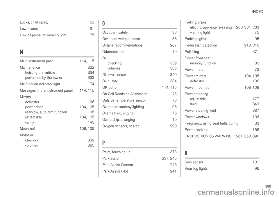
INDEX
399
Locks, child safety 63
Low beams 91
Low oil pressure warning light 75
M
Main instrument panel 114, 115
Maintenance 332
hoisting the vehicle 334
performed by the owner 333
Malfunction indicator light 74
Messages in the instrument panel 114, 115Mirrors defroster 106
power door 104, 105
rearview, auto-dim function 106
retractable 104, 105
vanity 143
Moonroof 108, 109 Motor oil checking 339
volumes 385
O
Occupant safety 28
Occupant weight sensor 38
Octane recommendations 287
Odometer, trip 79Oilchecking 339
volumes 385
Oil level sensor 340
Oil quality 384
OK button 114, 115
On Call Roadside Assistance 25
Outside temperature sensor 78
Overhead courtesy lighting 98
Overheating, engine 76
Ownership, changing 19
Oxygen sensors, heated 290
P
Paint, touching up 373
Park assist 237, 245
Park Assist Camera 246
Park Assist Pilot 241
Parking brake electric, applying/releasing 280, 281, 283
warning light 75
Parking lights 95
Pedestrian detection 213, 216
Polishing 371Power front seat memory function 82
Power meter 72
Power mirrors 104, 105 defroster 106
Power moonroof 108, 109Power steering adjustable 177
fluid 343
Power steering fluid 387
Power windows 103
Pregnancy, using seat belts during 33
Private locking 156
PROPOSITION 65 WARNING 261, 358, 390
R
Rain sensor 101
Rear fog lights 96