tow bar VOLVO V60 2021 User Guide
[x] Cancel search | Manufacturer: VOLVO, Model Year: 2021, Model line: V60, Model: VOLVO V60 2021Pages: 661, PDF Size: 12.68 MB
Page 439 of 661
STARTING AND DRIVING
* Option/accessory.437
Checking trailer lights
When connecting a trailer, make sure that all of the lights on the trailer are functioningbefore starting to drive.
Trailer turn signals and brake lightsIf one or more of the turn signals or brake lights on the trailer is not working, a symboland message will be displayed in the instru-ment panel. The other lights on the trailermust be checked manually by the driver beforethe vehicle is driven.
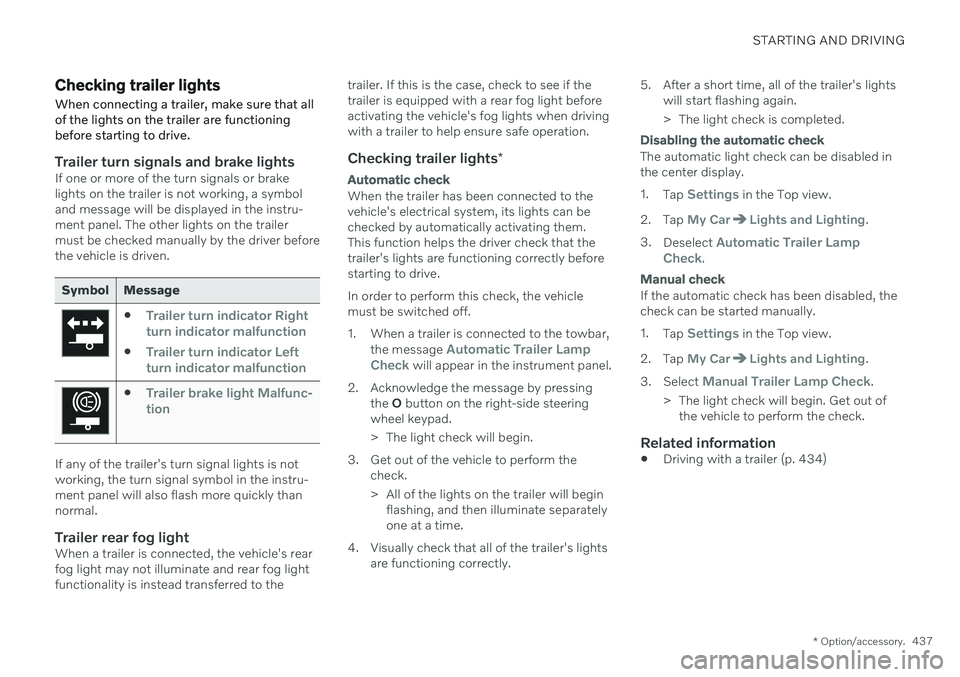
Symbol Message
Trailer turn indicator Right
turn indicator malfunction
Trailer turn indicator Left
turn indicator malfunction
Trailer brake light Malfunc-
tion
If any of the trailer's turn signal lights is not working, the turn signal symbol in the instru-ment panel will also flash more quickly thannormal.
Trailer rear fog lightWhen a trailer is connected, the vehicle's rearfog light may not illuminate and rear fog lightfunctionality is instead transferred to the trailer. If this is the case, check to see if thetrailer is equipped with a rear fog light beforeactivating the vehicle's fog lights when drivingwith a trailer to help ensure safe operation.
Checking trailer lights
*
Automatic check
When the trailer has been connected to the vehicle's electrical system, its lights can bechecked by automatically activating them.This function helps the driver check that thetrailer's lights are functioning correctly beforestarting to drive. In order to perform this check, the vehicle must be switched off.
1. When a trailer is connected to the towbar,
the message
Automatic Trailer Lamp
Check will appear in the instrument panel.
2. Acknowledge the message by pressing the O button on the right-side steering
wheel keypad.
> The light check will begin.
3. Get out of the vehicle to perform the check.
> All of the lights on the trailer will beginflashing, and then illuminate separately one at a time.
4. Visually check that all of the trailer's lights are functioning correctly. 5. After a short time, all of the trailer's lights
will start flashing again.
> The light check is completed.
Disabling the automatic check
The automatic light check can be disabled in the center display. 1.Tap
Settings in the Top view.
2. Tap
My CarLights and Lighting.
3. Deselect
Automatic Trailer Lamp
Check.
Manual check
If the automatic check has been disabled, the check can be started manually. 1. Tap
Settings in the Top view.
2. Tap
My CarLights and Lighting.
3. Select
Manual Trailer Lamp Check.
> The light check will begin. Get out of the vehicle to perform the check.
Related information
Driving with a trailer (p. 434)
Page 441 of 661
STARTING AND DRIVING
}}
439
Attaching and removing the towing eyelet
Use the towing eyelet when towing. Screw the towing eyelet securely into place in thethreaded outlet behind the cover on the right-hand side of the front and rear bumpers.
NOTE
If the vehicle is equipped with a towbar, there is no rear attachment for the towingeye.
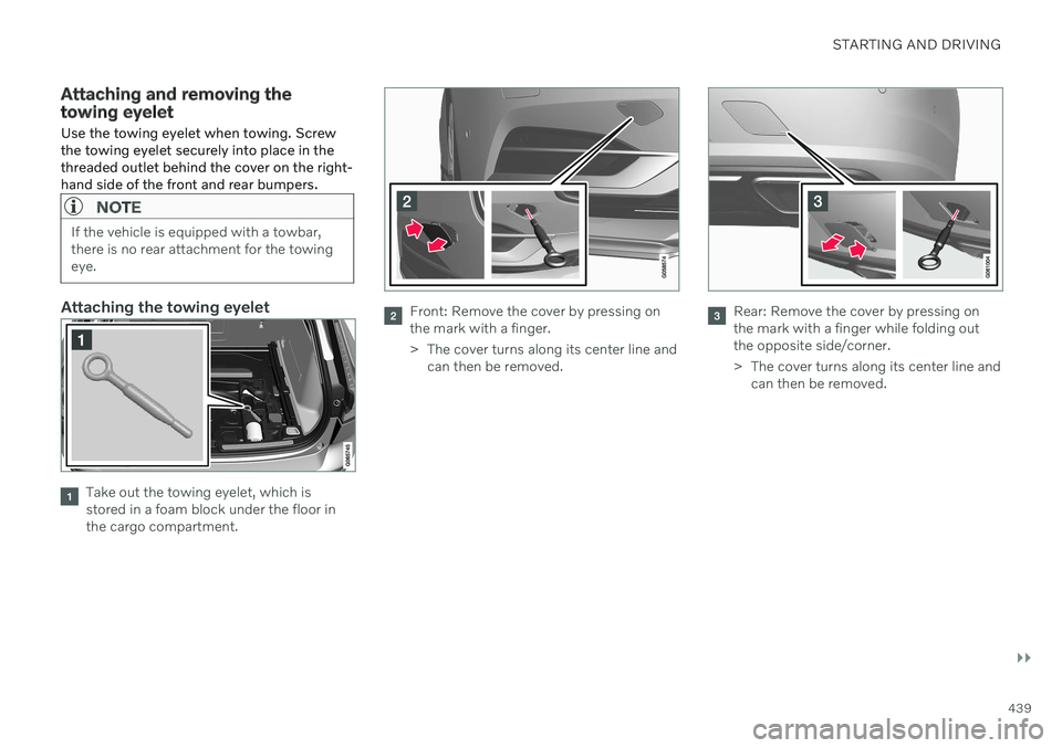
Attaching the towing eyelet
Take out the towing eyelet, which is stored in a foam block under the floor inthe cargo compartment.
Front: Remove the cover by pressing on the mark with a finger.
> The cover turns along its center line and can then be removed.Rear: Remove the cover by pressing on the mark with a finger while folding outthe opposite side/corner.
> The cover turns along its center line andcan then be removed.
Page 547 of 661
WHEELS AND TIRES
}}
545
8. Start the compressor by moving the
switch to the I (On) position.
When the compressor starts, the pressure
can increase up to 6 bar (88 psi), but thepressure will decrease afterapprox. 30 seconds.
WARNING
Never stand next to a tire being inflated with the compressor. If cracks, bulges, etc.form on the tire, switch off the compressorimmediately. The vehicle should not bedriven. Call roadside assistance to have thevehicle towed to a workshop for inspec-tion/replacement of the tire. Volvo recom-mends an authorized workshop.
9. Inflate the tire for 7 minutes.
CAUTION
To help avoid overheating, the compressor should never be used for more than10 minutes at a time.
10. Switch off the compressor and check the inflation pressure using the air pressure gauge. The inflation pressure should bebetween 1.8 bar (22 psi) and 3.5 bar(51 psi). If the inflation pressure is toohigh, use the air release valve to releaseair.
WARNING
If pressure falls below 1.8 bar (22 psi), the hole in the tire may be too large. The vehi-cle should not be driven. Call roadsideassistance to have the vehicle towed to aworkshop for inspection/replacement ofthe tire. Volvo recommends an authorizedworkshop.
11. Switch off the compressor and remove the electrical cable.
12. Unscrew the hose from the tire's valve and screw the valve cap back on.
NOTE
After inflating a tire, always replace the valve cap to help prevent valve damagecaused by gravel, dirt, etc.
Use plastic valve caps only. Metal capscould corrode and become difficult toremove.
13. Put the protective hose cover onto the
hose to help prevent leakage of any resid- ual sealing compound. Return the equip-ment to the cargo compartment.
14. Immediately drive the vehicle at least 3 km (2 miles) at a maximum speed of80 km/h (50 mph) to allow the sealingcompound to seal the tire, and thenrecheck the inflation pressure.
WARNING
During the tire's first revolution, some seal- ing compound may spray out of the punc-ture hole. Before driving away, make surethat no one is near the vehicle who couldbe sprayed with sealing compound. Makesure no one is within 2 meters (7 feet) ofthe vehicle.
15. Rechecking the inflation pressure Connect the hose to the tire's valve and screw the hose connector onto the valveas far as possible. The compressor mustbe switched off.
Page 548 of 661
||
WHEELS AND TIRES
54616. Check the inflation pressure on the air
pressure gauge.
If the pressure is under 1.3 bar (19 psi), the tire is not sufficiently sealed. Thevehicle should not be driven. Call road-side assistance to have the vehicletowed.
If the inflation pressure is higher than1.3 bar (19 psi), the tire must be inflatedto the inflation pressure specified onthe tire pressure decal on the driver'sside door pillar (1 bar = 100 kPa =14.5 psi). If the inflation pressure is toohigh, use the air release valve to releaseair.
WARNING
Check inflation pressure regularly.
Volvo recommends driving to the nearest authorized Volvo workshop to have the tirereplaced/repaired. Inform the workshop thatthe tire contains sealing compound. The sealing compound bottle and the hose must be replaced after use. Volvo recom-mends contacting an authorized Volvo work-shop for replacement.
WARNING
After using the tire sealing system, the vehicle should not be driven farther thanapproximately 200 km (120 miles).
NOTE
The compressor is an electric device. Fol- low local regulations for disposal.
Related information
Recommended tire pressure (p. 529)
Tire sealing system (p. 542)
Inflate tires with the compressor included in the tire sealing system (p. 546)
Contacting Volvo (p. 26)
Inflate tires with the compressor included in the tire sealing system
The vehicle's original tires can be inflated using the compressor in the tire sealing sys-tem.
1. The compressor must be switched off. Make sure that the switch is in the 0 (Off)
position and take out the electrical cable and the hose.
2. Unscrew the tire's valve cap and screw the hose's valve connector as far as possi-ble onto the valve. Be sure the air release valve on the com- pressor's hose is completely closed.
3. Connect the electrical cable to the nearest 12 V outlet and start the vehicle.
WARNING
Inhaling exhaust fumes could lead to seri- ous injury. Never leave the engine runningin an enclosed space or a space withoutsufficient ventilation.
WARNING
Never leave children unattended in the vehicle while the engine is running.
Page 549 of 661
WHEELS AND TIRES
}}
547
4. Start the compressor by moving the
switch to the I (On) position.
CAUTION
Risk of overheating. The compressor should not be running for longer than 10minutes at a time.
5. Inflate the tire to the pressure specified on
the tire pressure decal on the driver's side door pillar. If the inflation pressure is toohigh, use the air release valve to releaseair.
6. Switch off the compressor. Remove the hose and the electrical cable.
7. Screw the valve cap back onto the tire.
NOTE
After inflating a tire, always replace the valve cap to help prevent valve damagecaused by gravel, dirt, etc.
Use plastic valve caps only. Metal capscould corrode and become difficult toremove.
NOTE
The compressor is an electric device. Fol- low local regulations for disposal.
Related information
Recommended tire pressure (p. 529)
Using the tire sealing system (p. 543)
Tire sealing system (p. 542)
Determining the vehicle's permitted weight
Properly loading your vehicle will provide maximum return of vehicle design perform-ance.
Weight designationsBefore loading your vehicle, familiarize your- self with the following terms for determiningyour vehicle's weight ratings, with or without atrailer, from the vehicle's Federal/CanadianMotor Vehicle Safety Standards (FMVSS/CMVSS) label, and the vehicle's tire informa-tion placard:
Curb weight
The weight of the vehicle including a full tank of fuel and all standard equipment. It does notinclude passengers, cargo, or optional equip-ment.
Capacity weight
All weight added to the curb weight, including cargo and optional equipment. When towing,towbar weight is also part of cargo weight.
Permissible axle weight
The maximum allowable weight that can be carried by a single axle (front or rear). Thesenumbers are shown on the Federal/CanadianMotor Vehicle Safety Standards (FMVSS/CMVSS) label. The total load on each axlemust never exceed its maximum permissibleweight.
Page 576 of 661
||
MAINTENANCE AND SERVICE
* Option/accessory.
574
WARNING
Apply the parking brake and put the gear selector in the Park (
P) position.
Block the wheels standing on theground, use rigid wooden blocks orlarge stones.
Check that the jack is not damaged,the threads are properly lubricated andit is free from dirt.
Be sure the jack is on a firm, level, non-slippery surface and that it is uprightand not leaning.
The jack must correctly engage in thejack attachment.
No objects should be placed betweenthe base of the jack and the ground, orbetween the jack and the attachmentbar on the vehicle.
Never let anyone remain in the vehiclewhen it is raised on a jack.
If a tire must be changed near passingtraffic, make sure all passengers moveto a safe location.
Use a jack intended for the vehiclewhen changing a tire. For any otherjob, use stands to support the vehicle.
Never crawl under or allow any part of your body to be extended under a vehi-cle supported by a jack.
WARNING
If the vehicle is lifted on a garage jack, the jack must be placed under one of the fourlifting points. Make sure that the vehicle iscorrectly positioned on the jack and that itcannot slide off. Make sure the jack platehas a rubber pad to help keep the vehiclestable and prevent damage. Always useaxle stands or similar.
When not in use, the jack * should be kept in
its storage compartment under the cargo compartment floor. Read through all instructions before starting. Before raising the vehicle using a jack or lift,take out all the tools you will need.
1. Turn on the vehicle's hazard warning flashers if e.g. a wheel change must be performed in an area with traffic.
2. Apply the parking brake and put the gear selector in P, or first gear if the vehicle has
a manual transmission. If the vehicle is equipped with
Leveling
Control* , this feature must be turned off
before the vehicle is lifted onto a tow truck. 3. Place chocks in front of and behind the
wheels that are still on the ground. Forexample, use heavy wooden blocks orlarge stones.
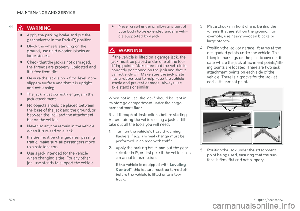
4. Position the jack or garage lift arms at the designated points under the vehicle. Thetriangle markings on the plastic cover indi-cate where the jack attachment points/lift-ing points are located. There are two jackattachment points on each side of thevehicle. There is a groove for the jack ateach attachment point.
5. Position the jack under the attachmentpoint being used, ensuring that the sur- face is firm, flat and not slippery.
Page 606 of 661

||
MAINTENANCE AND SERVICE
* Option/accessory.
604
Positions
Function Ampere Type
– –
MCaseA
–
–
MCaseA
Pneumatic suspension
* compressor 40
MCaseA
–
–
MCaseA
–
–
MCaseA
–
–
MCaseA
Door module right side, rear
20
MCaseA
–
–
MCaseA
– –
– –
Power tailgate* 25
MCaseA
Power front passenger seat
*
Door module right side, front 20
MCaseA
Towbar
* control module 40
MCaseA
Seat belt tensioner module (right side)
40
MCaseA
Internal relay windings
5 Micro
Page 607 of 661
MAINTENANCE AND SERVICE
}}
* Option/accessory.605
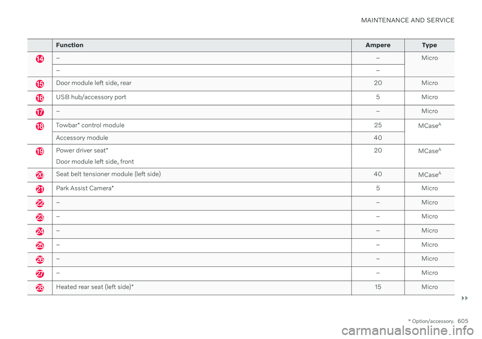
Function Ampere Type
– – Micro
– –
Door module left side, rear20 Micro
USB hub/accessory port 5 Micro
–– Micro
Towbar* control module 25
MCaseA
Accessory module 40
Power driver seat*
Door module left side, front 20
MCaseA
Seat belt tensioner module (left side)
40
MCaseA
Park Assist Camera
* 5 Micro
–
– Micro
–– Micro
–– Micro
–– Micro
–– Micro
–– Micro
Heated rear seat (left side)* 15 Micro