coolant VOLVO V90 2017 Owners Manual
[x] Cancel search | Manufacturer: VOLVO, Model Year: 2017, Model line: V90, Model: VOLVO V90 2017Pages: 594, PDF Size: 15.07 MB
Page 12 of 594
10
WHEELS AND TYRES
Tyres482
Tyres' rotation direction 483
Tread wear indicators on the tyres 484
Checking the tyre pressures 484
Tyre monitoring *
485
Checking tyre pressure with the tyre monitoring system * 487
Rectifying low tyre pressure with tyremonitoring * 488
Calibrating tyre monitoring *
489
Emergency puncture repair kit 490
Using the emergency puncture repair kit 491
Inflate tyres with the compressor from the emergency puncture repair kit 494
When changing wheels 495
Removing a wheel 495
Fitting the wheels 497
Wheel bolts 498
Spare wheel *
498
Winter wheels 499
Tool kit 500
Warning triangle 500
Jack *
501
First aid kit 501
Dimension designation for wheel rim 502
Dimension designation for tyre502
MAINTENANCE AND SERVICE
Volvo service programme506
Car status 506
Book service and repair 506
Inspection and service of the system for vehicle gas * 509
Remote updates 509
System updates 510
Data transmission between car and workshop 511
Raise the car 512
Opening and closing the bonnet 514
Engine compartment overview 515
Engine oil 516
Checking and filling with engine oil 517
Topping up coolant 518
Servicing the climate control system 520
Bulb replacement 520
Replacing the dipped beam bulb 522
Replacing the main beam lamp 523
Replacing daytime running lightbulb/position lamp bulb, front 524
Replacing the front direction indica-tor bulb 524
Replacing the reversing lamp bulb 525
Replacing the rear fog lamp bulb 526
Bulb specifications 526
Page 13 of 594
11
Wiper blades in service position527
Replacing a wiper blade 528
Filling washer fluid 529
Starter battery 530
Symbols on the batteries 533
Support battery 533
Fuses 535
Replacing a fuse 536
Fuses in engine compartment 537
Fuses under glovebox 542
Fuses in cargo area 546
Cleaning the exterior 549
Polishing and waxing 551
Rustproofing 552
Cleaning the interior 552
Cleaning the centre display 553
Paint damage 554
Repairing paint damage 555
SPECIFICATIONS
Type designations558
Dimensions 561
Weights 563
Towing capacity and towball load 564
Engine specifications 566
Engine oil — specifications 567
Adverse driving conditions for engine oil 569
Coolant — specifications 570
Transmission fluid — specifications 570
Brake fluid — specifications 570
Fuel tank - volume 571
Air conditioning — specifications 571
Fuel consumption and CO2 emissions 572
Approved tyre pressures 574
Performance 575
ALPHABETICAL INDEX
Alphabetical Index 577
Page 23 of 594
INTRODUCTION
21
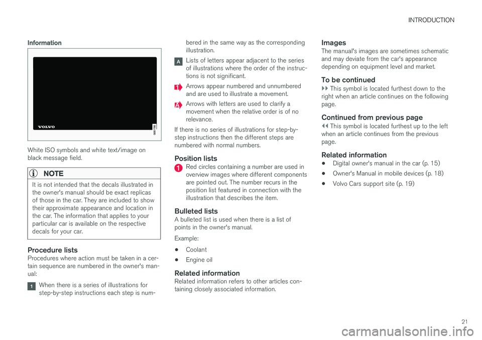
Information
White ISO symbols and white text/image on black message field.
NOTE
It is not intended that the decals illustrated in the owner's manual should be exact replicasof those in the car. They are included to showtheir approximate appearance and location inthe car. The information that applies to yourparticular car is available on the respectivedecals for your car.
Procedure listsProcedures where action must be taken in a cer- tain sequence are numbered in the owner's man-ual:
When there is a series of illustrations for step-by-step instructions each step is num-bered in the same way as the correspondingillustration.
Lists of letters appear adjacent to the series of illustrations where the order of the instruc-tions is not significant.
Arrows appear numbered and unnumbered and are used to illustrate a movement.
Arrows with letters are used to clarify a movement when the relative order is of norelevance.
If there is no series of illustrations for step-by-step instructions then the different steps arenumbered with normal numbers.
Position listsRed circles containing a number are used in overview images where different componentsare pointed out. The number recurs in theposition list featured in connection with theillustration that describes the item.
Bulleted listsA bulleted list is used when there is a list ofpoints in the owner's manual. Example:
• Coolant
• Engine oil
Related informationRelated information refers to other articles con- taining closely associated information.
ImagesThe manual's images are sometimes schematicand may deviate from the car's appearancedepending on equipment level and market.
To be continued
}}
This symbol is located furthest down to the
right when an article continues on the following page.
Continued from previous page
|| This symbol is located furthest up to the left
when an article continues from the previous page.
Related information
• Digital owner's manual in the car (p. 15)
• Owner's Manual in mobile devices (p. 18)
• Volvo Cars support site (p. 19)
Page 416 of 594
||
STARTING AND DRIVING
414
IMPORTANT
Engine damage can occur if water enters the air filter. In depths greater than 25 cm, water could enter the transmission. This reduces the lubri-cating ability of the oils and shortens theservice life of these systems. Damage to any component, engine, transmis- sion, turbocharger, differential or its internalcomponents caused by flooding, hydrostaticlocking or oil shortage, is not covered by thewarranty. In the event of the engine stalling in water, do not try restart - tow the car from the water toa workshop - an authorised Volvo workshop isrecommended. Risk of engine breakdown.
Related information
•Towing (p. 431)
• Recovering the car (p. 432)
Overheating in the engine and drive system
Under special conditions, for example hard driv- ing in hilly terrain and hot climate, there is a riskthat the engine and drive system may overheat -in particular with a heavy load.
• In the event of overheating, the engine's power may be limited temporarily.
• Remove any auxiliary lamps from in front ofthe grille when driving in hot climates.
• If the temperature in the engine's coolingsystem becomes too high then a warningsymbol is illuminated and the driver display shows the message
Engine temperature
High temperature Stop safely. Stop the
car in a safe way and allow the engine to run at idling speed for several minutes and cooldown.
• If the message
Engine temperature High
temperature Turn off engine or Engine
coolant Level low, turn off engine is
shown, stop the car and switch off the engine.
• In the event of overheating in the gearbox, analternative gear shift program will beselected. In addition, a built-in protectionfunction is activated that, amongst otherthings, illuminates a warning symbol and thedriver display shows the message
Transmission warm Reduce speed to
lower temperature or Transmission hot Stop safely, wait for cooling
. Follow the
recommendation given, reduce speed or stop the car in a safe way and allow the engine torun at idling speed for several minutes toenable the gearbox to cool down.
• If the car overheats, the air conditioning maybe switched off temporarily.
• Do not turn the engine off immediately youstop after a hard drive.
NOTE
It is normal for the engine's cooling fan to operate for a time after the engine has beenswitched off.
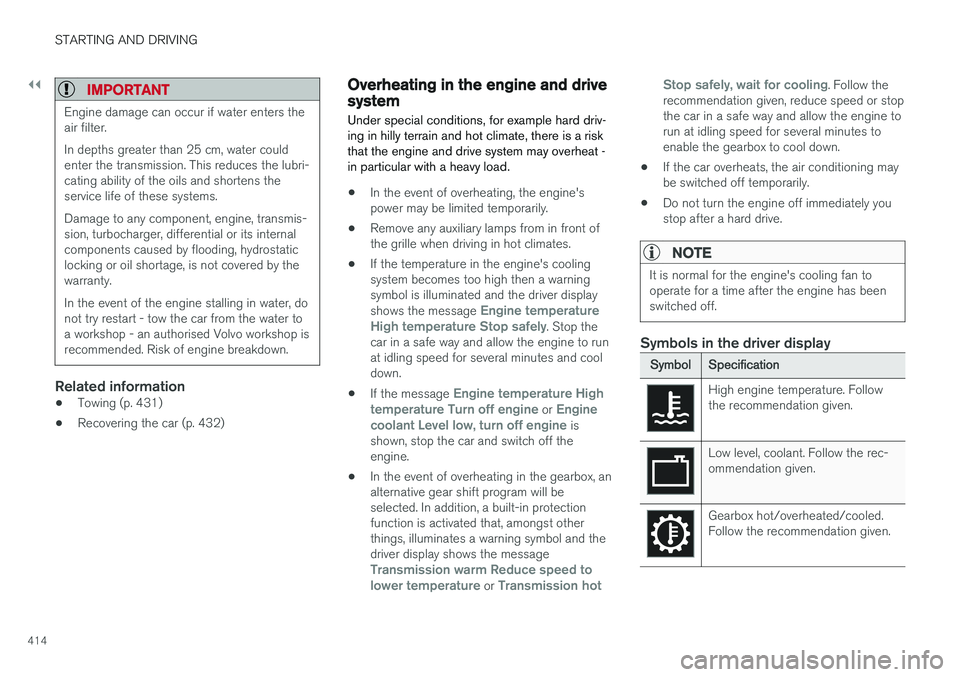
Symbols in the driver display
Symbol
Specification
High engine temperature. Follow the recommendation given.
Low level, coolant. Follow the rec- ommendation given.
Gearbox hot/overheated/cooled. Follow the recommendation given.
Page 418 of 594
STARTING AND DRIVING
* Option/accessory.
416 •
Speed camera information
* (p. 350)
• Driving with a trailer (p. 426)
• Driving in water (p. 413)
• Alarm
* (p. 262)
• Level control
* and shock absorption (p. 405)
• Warning triangle (p. 500)
• Emergency puncture repair kit (p. 490)
• Spare wheel
* (p. 498)
Winter driving
For winter driving it is important to perform cer- tain checks of the car in order to ensure that itcan be driven safely.
Check the following in particular before the cold season:
• The engine coolant must contain 50% glycol.This mixture protects the engine againstfrost erosion down to approximately –35 °C.To avoid health risks, different types of glycolmust not be mixed.
• The fuel tank must be kept filled to preventcondensation.
• Engine oil viscosity is important. Oils withlower viscosity (thinner oils) facilitate startingin cold weather and also reduce fuel con-sumption while the engine is cold. Readmore about suitable oils in the section"Adverse driving conditions for engine oil".
IMPORTANT
Low viscosity oil must not be used for hard driving or in hot weather.
• The condition of the starter battery and charge level must be inspected. Coldweather places great demands on the starter battery and its capacity is reduced by thecold.
• Use washer fluid with antifreeze to avoid iceforming in the washer fluid reservoir.
Slippery driving conditionsTo achieve optimum roadholding Volvo recom-mends using winter tyres on all wheels if there isa risk of snow or ice.
NOTE
The use of winter tyres is a legal requirement in certain countries. Studded tyres are notpermitted in all countries.
Practise driving on slippery surfaces under con- trolled conditions to learn how the car reacts.
Related information
•Topping up coolant (p. 518)
• Adverse driving conditions for engine oil(p. 569)
• Starter battery (p. 530)
• Winter wheels (p. 499)
• Filling washer fluid (p. 529)
• Replacing a wiper blade (p. 528)
• Parking climate
* (p. 206)
• Activating/deactivating defrost of windowsand door mirrors (p. 194)
Page 517 of 594
MAINTENANCE AND SERVICE
515
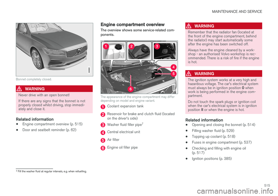
Bonnet completely closed.
WARNING
Never drive with an open bonnet! If there are any signs that the bonnet is not properly closed whilst driving, stop immedi-ately and close it.
Related information
•Engine compartment overview (p. 515)
• Door and seatbelt reminder (p. 62)
Engine compartment overview
The overview shows some service-related com- ponents.
The appearance of the engine compartment may differ depending on model and engine variant.
Coolant expansion tank
Reservoir for brake and clutch fluid (located on the driver's side)
Washer fluid filler pipe 7
Central electrical unit
Air filter
Engine oil filler pipe
WARNING
Remember that the radiator fan (located at the front of the engine compartment, behindthe radiator) may start automatically someafter the engine has been switched off. Always have the engine cleaned by a work- shop - an authorised Volvo workshop is rec-ommended. There is a risk of fire if the engineis hot.
WARNING
The ignition system works at a very high and hazardous voltage. The car's electrical system must always be in ignition position
0 when
work is being performed in the engine com- partment. Do not touch the spark plugs or ignition coil when the car's electrical system is in ignition position II or when the engine is hot.
Related information
• Opening and closing the bonnet (p. 514)
• Filling washer fluid (p. 529)
• Topping up coolant (p. 518)
• Fuses in engine compartment (p. 537)
• Checking and filling with engine oil (p. 517)
• Ignition positions (p. 385)
7
Fill the washer fluid at regular intervals, e.g. when refuelling.
Page 520 of 594
||
MAINTENANCE AND SERVICE
518
NOTE
If the right conditions for measuring the oil level (time after engine shutdown, the car'sinclination, outside temperature, etc.) are not met, then the message
No value availablewill be shown in the centre display. This does not mean that there is something wrong in
the car's systems.
Related information
• Engine oil (p. 516)
• Engine oil — specifications (p. 567)
• Adverse driving conditions for engine oil (p. 569)
• Ignition positions (p. 385)
• Car status (p. 506)
Topping up coolant
The coolant cools the internal combustion engine to the correct operating temperature. Theheat that is transferred from the engine to thecoolant can be used to heat the passenger com-partment.
When topping up the coolant, follow the instruc- tions on the packaging. Never top up with wateronly. The risk of freezing increases with both toolittle and too much coolant concentrate.
WARNING
Coolant can be very hot. If the coolant requires topping up when the engine is atoperating temperature, unscrew the expan-sion tank cap slowly to gently release theoverpressure.
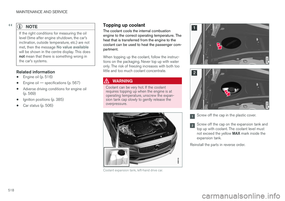
Coolant expansion tank, left-hand drive car.
Screw off the cap in the plastic cover.
Screw off the cap on the expansion tank and top up with coolant. The coolant level must not exceed the yellow MAX mark inside the
expansion tank.
Reinstall the parts in reverse order.
Page 521 of 594
MAINTENANCE AND SERVICE
519
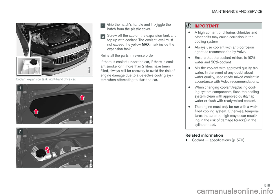
Coolant expansion tank, right-hand drive car.
Grip the hatch's handle and lift/jiggle the hatch from the plastic cover.
Screw off the cap on the expansion tank and top up with coolant. The coolant level must not exceed the yellow MAX mark inside the
expansion tank.
Reinstall the parts in reverse order. If there is coolant under the car, if there is cool- ant smoke, or if more than 2 litres have beenfilled, always call for recovery to avoid the risk ofengine damage due to a defective cooling sys-tem when attempting to start the car.
IMPORTANT
• A high content of chlorine, chlorides and other salts may cause corrosion in thecooling system.
• Always use coolant with anti-corrosionagent as recommended by Volvo.
• Ensure that the coolant mixture is 50%water and 50% coolant.
• Mix the coolant with approved quality tapwater. In the event of any doubt aboutwater quality, used ready-mixed coolant inaccordance with Volvo recommendations.
• When changing coolant/replacing cool-ing system components, flush the coolingsystem clean with approved quality tapwater or flush with ready-mixed coolant.
• The engine must only be run with a well-filled cooling system. Otherwise, tempera-tures that are too high may occur result-ing in the risk of damage (cracks) in thecylinder head.
Related information
•
Coolant — specifications (p. 570)
Page 547 of 594
MAINTENANCE AND SERVICE
* Option/accessory.545
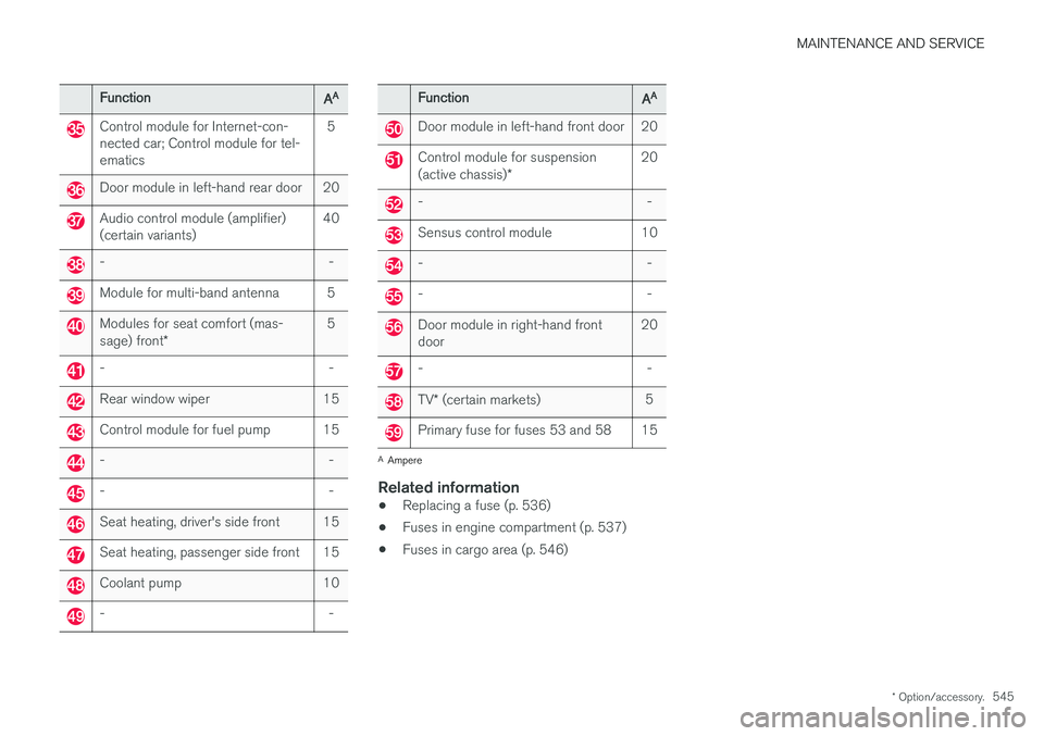
Function
AA
Control module for Internet-con- nected car; Control module for tel-ematics 5
Door module in left-hand rear door 20
Audio control module (amplifier) (certain variants)
40
- -
Module for multi-band antenna 5
Modules for seat comfort (mas- sage) front
* 5
- -
Rear window wiper 15
Control module for fuel pump 15
- -
- -
Seat heating, driver's side front 15
Seat heating, passenger side front 15
Coolant pump 10
- -
Function
AA
Door module in left-hand front door 20
Control module for suspension (active chassis)
* 20
- -
Sensus control module 10
- -
- -
Door module in right-hand front door
20
- -
TV
* (certain markets) 5
Primary fuse for fuses 53 and 58 15
A
Ampere
Related information
• Replacing a fuse (p. 536)
• Fuses in engine compartment (p. 537)
• Fuses in cargo area (p. 546)
Page 568 of 594
SPECIFICATIONS
566
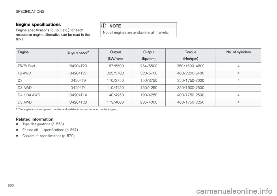
Engine specificationsEngine specifications (output etc.) for each respective engine alternative can be read in thetable.NOTE
Not all engines are available in all markets.
Engine Engine codeA
Output
(kW/rpm) Output
(hp/rpm) Torque
(Nm/rpm) No. of cylinders
T5/Bi-Fuel B4204T23 187/5500 254/5500 350/1500–4800 4
T6 AWD B4204T27 235/5700 320/5700 400/2200-5400 4
D3 D4204T9 110/3750 150/3750 320/1750-3000 4
D3 AWD D4204T4 110/4250 150/4250 350/1500-2500 4
D4 / D4 AWD D4204T14 140/4250 190/4250 400/1750-2500 4
D5 AWD D4204T23 173/4000 235/4000 480/1750-2250 4
A The engine code, component number and serial number can be found on the engine.
Related information
• Type designations (p. 558)
• Engine oil — specifications (p. 567)
• Coolant — specifications (p. 570)