tailgate VOLVO V90 CROSS COUNTRY 2017 Quick Guide
[x] Cancel search | Manufacturer: VOLVO, Model Year: 2017, Model line: V90 CROSS COUNTRY, Model: VOLVO V90 CROSS COUNTRY 2017Pages: 184, PDF Size: 5.75 MB
Page 60 of 184

IMPORTANT INFORMATION
58
Door and seat belt reminders
Graphics in the instrument panel
Warning colors for doors/tailgate vary depending on the vehicle's speed (generic illustration)
The instrument panel graphic shows the seats where seat belts are not buckled. The same graphic also indicates if a door, the hood, tailgate or fuel filler door is/are open. This graphic disappears automatically after approx. 30 seconds or if the if the O button on
the steering wheel keypad is pressed.
Seat belt reminder
Seat belt reminder light in ceiling console
The seat belt reminder consists of an audible signal, an indicator light nearthe rearview mirror and a symbol in theinstrument panel that alert all occu-
pants of the vehicle to buckle their seat belts.
The audible signal is speed-dependent and will sound for several seconds. If the driver's or a passenger's seat belt is not buckled, this will be indicated in the instrumentpanel. Child seats are not included in the seat belt reminder system.
Front seats
An audible signal and an indicator light will remind the driver and front seat passenger tobuckle their seat belts.
Rear seats
The rear seat belt reminder has two functions.
• It indicates which seat belts are buckled in the rear seats. This will also be displayed inan instrument panel graphic.
• It also provides audio and visual reminders ifa rear seat belt is unbuckled while the vehi-cle is in motion. The reminders will disappearwhen the seat belt has been buckled again or can be erased by pressing the
O button
on the steering wheel keypad.
Door/hood/tailgate/fuel filler door
reminder
If a door, the hood, tailgate or fuel filler door is/are not properly closed, this will be indicated ina graphic in the instrument panel. Stop the vehi-cle safely and close the source of the reminder.
If the vehicle is moving at a speedunder approx.6 mph (10 km/h), theinformation symbol will illuminate in theinstrument panel.
At speeds above approx. 6 mph (10 km/h), the warning symbol will illu-minate in the instrument panel.
Related information
•Seat belts (p. 54)
• Buckling and unbuckling seat belts (p. 56)
• Seat belt pretensioners (p. 55)
Page 92 of 184

PRACTICAL INFORMATION
* Option/accessory.
90
Using the glove compartment
The glove compartment provides storage space for small items.
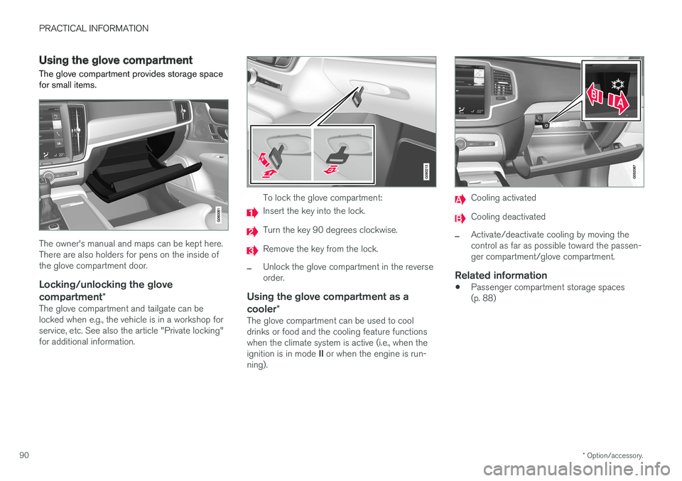
The owner's manual and maps can be kept here. There are also holders for pens on the inside ofthe glove compartment door.
Locking/unlocking the glove
compartment *
The glove compartment and tailgate can belocked when e.g., the vehicle is in a workshop forservice, etc. See also the article "Private locking"for additional information.
To lock the glove compartment:
Insert the key into the lock.
Turn the key 90 degrees clockwise.
Remove the key from the lock.
–Unlock the glove compartment in the reverse order.
Using the glove compartment as a cooler*
The glove compartment can be used to cool drinks or food and the cooling feature functionswhen the climate system is active (i.e., when the ignition is in mode II or when the engine is run-
ning).
Cooling activated
Cooling deactivated
–Activate/deactivate cooling by moving the control as far as possible toward the passen-ger compartment/glove compartment.
Related information
• Passenger compartment storage spaces(p. 88)
Page 101 of 184

PRACTICAL INFORMATION
}}
* Option/accessory.99
Fully open
1. Grasp the handle and pull out the cover
above the side panels in the cargo compart- ment as far as possible.
2. With the cover completely open, press the attaching pins on the rear corners of thecover into the grooves in the side panels andrelease the cover slightly while pressing thehandle lightly downward to hook the pins intothe grooves.
> The cover will remain in the fully openposition.
Partially retracted (loading) position
From the fully open position:
–Move the handle to release the attaching pins from the hooks.
> The cover will open until it reaches the partially retracted position.
In vehicles equipped with the automatic cargo compartment cover *, if the cover is fully open, it
will move automatically to the partially retracted position whenever the tailgate is opened and willreturn to the fully open position when the tailgateis closed. To fully open the cover from the partially open position:
1. Grasp the handle and pull the cover out to the fully open position.
2. Release the handle so that the pins engage in the hooks.
> The cover will remain in the fully openposition. In models equipped with the electrically operated cargo compartment cover
*, the cover will retract
from the fully open position to the loading posi- tion each time the tailgate is opened and returnto the fully open position when the tailgate isclosed. If the cover is obstructed while moving, itis designed to return to the loading position auto-matically.
CAUTION
• Avoid placing any objects on the cover when it is open.
• The electrically operated cover may notbe able to move automatically at low pas-senger compartment temperatures.
• If there are large objects in the cargocompartment, put the electrically oper-ated cover in the fully retracted positionso that it does not come into contact withthe object(s) while moving.
WARNING
Keep fingers, hands, etc. clear of the electri- cally operated cargo area cover while it ismoving.
Page 139 of 184

PRACTICAL INFORMATION
}}
137
Replacing front turn signal bulbs On models with halogen headlights, the front turn signal bulb can be replaced by the owner.
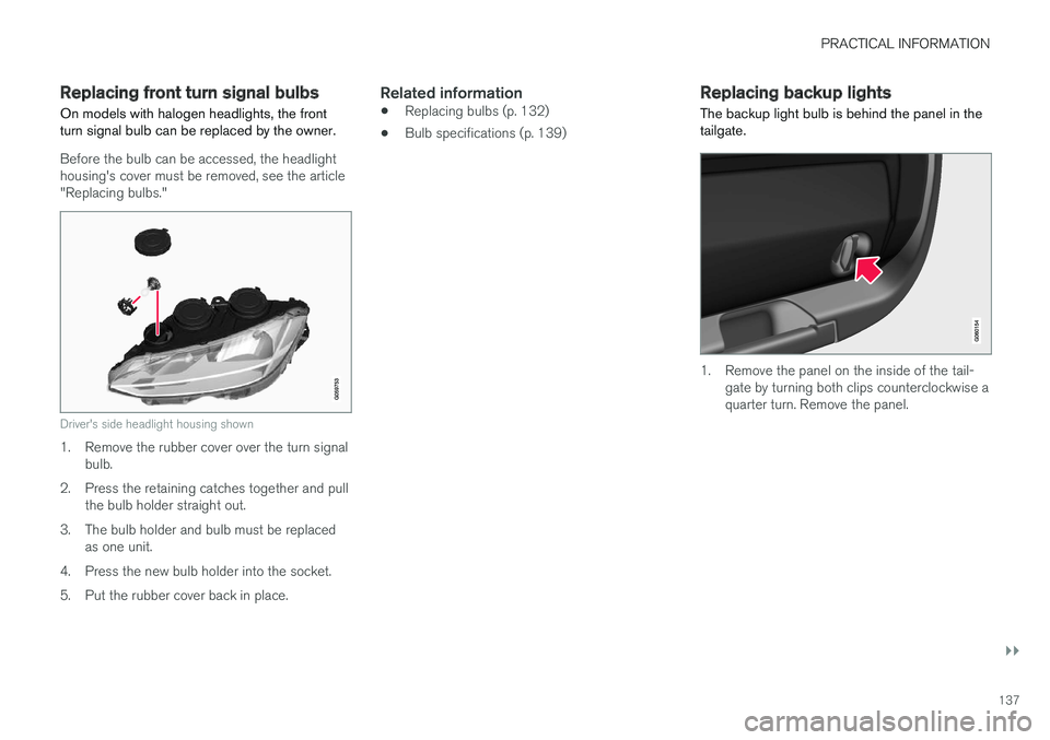
Before the bulb can be accessed, the headlight housing's cover must be removed, see the article"Replacing bulbs."
Driver's side headlight housing shown
1. Remove the rubber cover over the turn signalbulb.
2. Press the retaining catches together and pull the bulb holder straight out.
3. The bulb holder and bulb must be replaced as one unit.
4. Press the new bulb holder into the socket.
5. Put the rubber cover back in place.
Related information
• Replacing bulbs (p. 132)
• Bulb specifications (p. 139)
Replacing backup lights The backup light bulb is behind the panel in the tailgate.
1. Remove the panel on the inside of the tail-
gate by turning both clips counterclockwise a quarter turn. Remove the panel.
Page 140 of 184

||
PRACTICAL INFORMATION
138
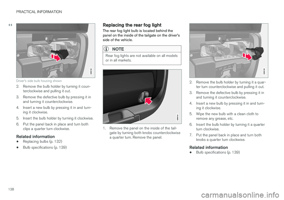
Driver's side bulb housing shown
2. Remove the bulb holder by turning it coun-terclockwise and pulling it out.
3. Remove the defective bulb by pressing it in and turning it counterclockwise.
4. Insert a new bulb by pressing it in and turn- ing it clockwise.
5. Insert the bulb holder by turning it clockwise.
6. Put the panel back in place and turn both clips a quarter turn clockwise.
Related information
• Replacing bulbs (p. 132)
• Bulb specifications (p. 139)
Replacing the rear fog light The rear fog light bulb is located behind the panel on the inside of the tailgate on the driver'sside of the vehicle.
NOTE
Rear fog lights are not available on all models or in all markets.
1. Remove the panel on the inside of the tail-
gate by turning both knobs counterclockwise a quarter turn. Remove the panel.
2. Remove the bulb holder by turning it a quar- ter turn counterclockwise and pulling it out.
3. Remove the defective bulb by pressing it in and turning it counterclockwise.
4. Insert a new bulb by pressing it in and turn- ing it clockwise.
5. Wipe the new bulb with a clean cloth to remove any grease, etc.
6. Insert the bulb holder by turning it a quarter turn clockwise.
7. Put the panel back in place and turn both knobs a quarter turn clockwise.
Related information
• Bulb specifications (p. 139)
Page 146 of 184

PRACTICAL INFORMATION
* Option/accessory.
144
Retractable towbar *
The Volvo retractable towbar is specially designed for the vehicle.
Overview
Weight decal
Ball cover
Safety wire attachment bracket
Trailer wiring socket
Folding out the towbar
1. Open the tailgate. There is a button for oper- ating the towbar on the right rear side of the cargo compartment. The indicator light in thebutton must glow steadily orange for thefolding function to be active.
2. Press and release the button. Holding in the button may prevent the towbar from folding out.
> The towbar will fold out partially andbecome visible under the bumper. The indicator light will flash orange.
NOTE
The towbar must complete the fold-out sequence before it can be moved to the fixedposition. This sequence may take a few sec-onds. If the towbar cannot be locked in thefixed position, wait for a few seconds and tryagain.
WARNING
Avoid standing close to the center of the rear bumper while the towbar is folding out.
Page 147 of 184

PRACTICAL INFORMATION
145
3. Pull up the towbar until it locks in the fixedposition. The indicator light in the button will glow steadily orange. Remove the cover fromthe towbar ball.
> The towbar is now ready for use.
WARNING
• Be sure the towbar is securely locked in position before attaching anything to it.
• Always attach the trailer's safety wiresecurely to the towbar's safety wireattachment bracket.
NOTE
An energy-saving mode activates after a short time and the indicator light will go out. Reacti-vate the folding towbar function by closingand then reopening the tailgate. If the vehicle's electrical system has detected an attached trailer, the indicator light will nolonger glow steadily.
Retracting the towbar
CAUTION
Be sure that no trailer wiring connector or adapter is connected to the towbar's electri-cal socket before retracting it.
1. Open the tailgate. Press the button for fold-
ing the towbar in/out on the right rear side of the cargo compartment.
> The towbar will automatically fold down tothe unlocked position. The indicator light in the button will flash orange.
WARNING
Never press the operating button if anything is attached to the towbar.
2. Fix the towbar in the retracted position by pushing it up under the bumper, where it will lock in place.
> The indicator light in the button will glowsteadily orange if the towbar is correctly locked in the retracted position.
Page 153 of 184

FUSES
}}
* Option/accessory.151
•
Fuses 18–30, 35–37, 46–54 and 55–70 are called "Micro".
• Fuses 31–34, 38–45 and 71–78 are called"MCase" and should only be replaced by atrained and qualified Volvo service technician.
Function
A
– –
– –
– –
– –
– –
Front USB socket* 5
12-volt socket in the front tun- nel console 15
12-volt socket on the rear side of the tunnel console15
12-volt socket in the cargo com- partment15
– –
Driver's side headlight, certain LED models15
Passenger's side headlight, cer- tain LED models15
Function
A
– –
Heated windshield*, driver side Shunt
Heated windshield
*, driver side 40
Headlight washers
*25
Windshield washer 25
– –
Horn 20
Alarm siren 5
Brake system control module (valves, parking brake) 40
Windshield wipers 30
Tailgate window washer 25
Heated windshield
*, passenger
side 40
– –
Brake system control module (ABS pump)
40
– –
Function
A
Heated windshield*, passenger
side Shunt
Feed when ignition is switched on to: engine control module,transmission components, elec-trical power steering, centralelectrical module; Brake system control module 5
– –
Passenger side headlight Passenger's side headlight, cer- tain LED models
7.5
15
– –
– –
Battery connection control mod- ule 5
Air bags; Occupant Weight Sen- sor (OWS)5
Driver side headlight Driver's side headlight, certain LED models7.5
15
Accelerator pedal sensor 5
Page 158 of 184

||
FUSES
* Option/accessory.
156
Function A
– –
Tailgate window wiper 15
Fuel pump control module 15
– –
– –
Driver side front seat heating*15
Passenger side front seat heating
*15
Coolant pump 10
– –
Front driver-side front door module 20
Active chassis control module
*20
– –
Sensus control module 10
– –
– –
Front passenger-side front door module 20
Function
A
– –
– –
Circuit breaker for fuses 53 and 58 15
A
Certain markets only.
Related information
• Fuses (p. 148)
• Replacing fuses (p. 148)
• Fuses in the engine compartment (p. 149)
• Fuses in the cargo compartment (p. 157)
Page 161 of 184

FUSES
* Option/accessory.159
Positions
•Fuses 13–17 and 21–36 are called "Micro".
• Fuses 1–12, 18–20 and 37 are called "MCase" and should only be replaced by atrained and qualified Volvo service technician.
Function
A
Heated rear window 30
– –
Pneumatic suspension* compressor 40
Lock motor for rear seat backrest, passenger's side 15
– –
Lock motor for rear seat backrest, driver's side15
– –
– –
Power tailgate
* 25
Power front seat (passenger side)
*
module 20
Trailer hitch
* control module 40
Seat belt tensioner module (pas- senger side) 40
Function
A
Internal relay windings 5
– –
Foot movement detection module for opening the power tailgate*5
– –
– –
Trailer hitch
* control module 25
Power front seat (driver seat
* mod-
ule 20
Seat belt tensioner module (driver side)
40
Parking camera
* 5
– –
– –
– –
– –
Airbag and seat belt tensioner modules 5
Function
A
Heated rear seat (driver side)*15
– –
Blind Spot Information (BLIS)
*5
– –
Seat belt tensioner modules 5
Emission system actuator 5
– –
All Wheel Drive control module
*15
Heated rear seat (passenger side)
*15
– –
Related information
•Replacing fuses (p. 148)
• Fuses (p. 148)
• Fuses in the passenger compartment (p. 153)
• Fuses in the engine compartment (p. 149)