load capacity VOLVO V90 CROSS COUNTRY 2018 Owner´s Manual
[x] Cancel search | Manufacturer: VOLVO, Model Year: 2018, Model line: V90 CROSS COUNTRY, Model: VOLVO V90 CROSS COUNTRY 2018Pages: 662, PDF Size: 11.93 MB
Page 320 of 662

||
DRIVER SUPPORT
* Option/accessory.
318
The driver is responsible for ensuring that the vehicle maintains a suitable distancefrom such obstacles.
• The camera and radar sensors do nothave the capacity to detect all oncomingobjects and obstacles in traffic environ-ments, e.g. potholes, stationary obstaclesor objects that completely or partiallyblock the route.
• Pilot Assist does not "see" pedestrians,animals, etc.
• The recommended steering input is lim-ited in force, which means that it cannotalways help the driver to steer and keepthe vehicle within the lane.
• Pilot Assist is switched off if the powersteering is working with reduced power -e.g. during cooling due to overheating(see section "Speed-dependent steeringforce").
The driver can always correct or adjust steeringassistance provided by Pilot Assist by turning thesteering wheel to the desired position.
Steep roads and/or heavy loadsPilot Assist is primarily intended to be driven onflat roads. The function may not be able to main-tain the correct time interval to the vehicle aheadwhen driving down steep hills. The driver should be extra attentive and prepared to apply thebrakes.
• Do not use Pilot Assist if the vehicle is carry-ing a heavy load or towing a trailer.
NOTE
Pilot Assist cannot be activated if a trailer, bike carrier or similar is connected to thevehicle electrical system.
Other limitations
•
The Off Road drive mode cannot be
selected when Pilot Assist is activated.
NOTE
The function uses the vehicle's camera unit, which has some general limitations – see thesection "Camera unit limitations".
NOTE
The function uses the vehicle's radar unit, which has some general limitations – see thesection "Radar unit limitations".
Related information
• Pilot Assist (p. 305)
• Speed-dependent steering wheel resistance (p. 266)
Pilot Assist
* symbols and messages
A number of symbols and messages relating to Pilot Assist may be displayed in the instrument panel and/or the head-up display *.
Page 340 of 662

DRIVER SUPPORT
338
City Safety limitations
City Safety functionality may be reduced in cer- tain situations.
Surroundings
Low objects
Hanging objects, such as flags for overhanging loads or accessories such as auxiliary lights orfront protective grids that extend beyond theheight of the hood, may limit City Safety function-ality.
Slippery road conditions
The extended braking distance on slippery roads may reduce City Safety's capacity to help avoid acollision. In these types of situations, the Anti-lock Braking System and Electronic Stability Con- trol (ESC 76
) will help provide optimal braking
power with maintained stability.
Backlighting
The visual warning signal in the windshield may be difficult to detect in bright sunlight, if there arereflections, or if the driver is wearing sunglassesor not looking straight ahead.
Heat
If the temperature in the passenger compartment is high due to e.g. bright sunlight, the visual warn-ing signal in the windshield may be temporarilydisabled.
Camera and radar sensor's field of vision
The camera's field of vision is limited and in cer- tain situations, it may be unable to detect pedes-trians, large animals, cyclists or vehicles, or it maydetect them later than expected. Vehicles that are dirty may be detected later than clean vehicles, and in dark conditions, motorcy-cles may be detected late or not at all. If a text message displayed in the instrument panel indicates that the camera/radar sensor isobstructed, it may be difficult for City Safety todetect pedestrians, large animals, cyclists, vehi-cles or lane markings in front of the vehicle. CitySafety functionality may therefore be reduced. Text messages may not be displayed for all situa- tions in which the windshield sensors areblocked. The driver must therefore always keepthe windshield in front of the camera/radar sen-sor clean.
CAUTION
Maintenance and replacement of City Safety components may only be performed by aworkshop – an authorized Volvo workshop isrecommended.
Driver intervention
Backing up
City Safety is temporarily deactivated when the vehicle is backing up.
Low speed
City Safety is not activated at very low speeds under 4 km/h (3 mph). The system will thereforenot intervene in situations in which your vehicle isapproaching another vehicle very slowly, such aswhen parking.
Active driver
Action by the driver always has priority. City Safety will therefore not react or will react at alater stage with a warning or intervention in situa-tions in which the driver is clearly steering andoperating the accelerator pedal, even if a collisionis unavoidable. An active and aware driving style may therefore delay collision warnings and intervention in order to minimize unnecessary warnings.
76 Electronic Stability Control
Page 447 of 662

STARTING AND DRIVING
}}
445
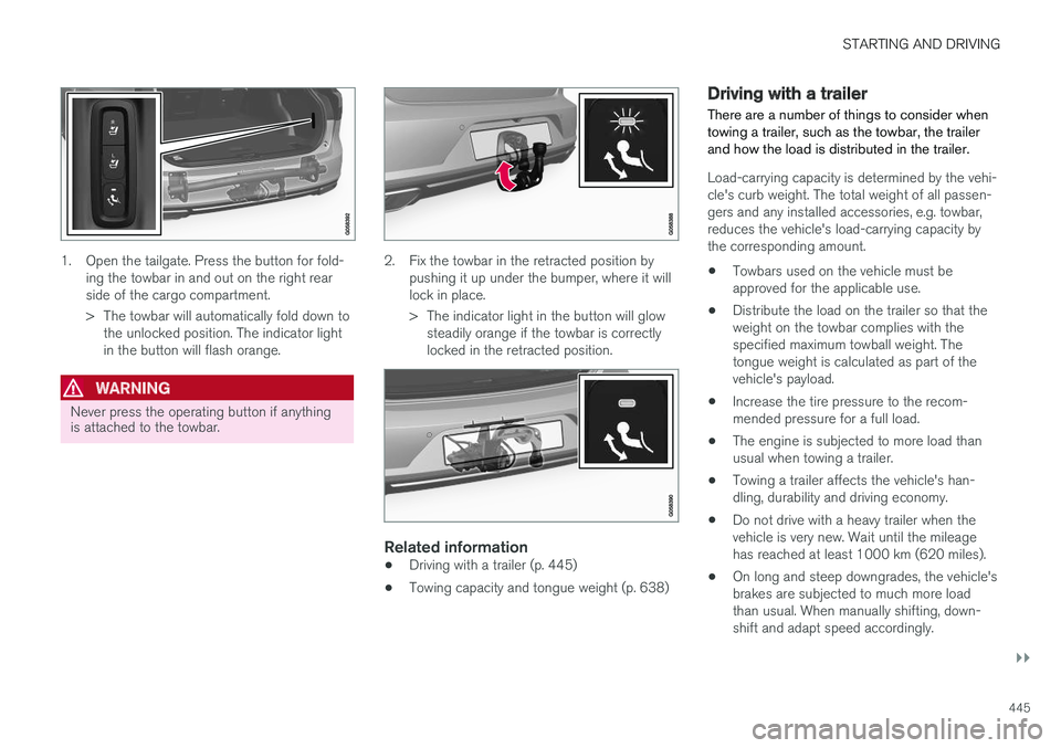
1. Open the tailgate. Press the button for fold-ing the towbar in and out on the right rear side of the cargo compartment.
> The towbar will automatically fold down tothe unlocked position. The indicator light in the button will flash orange.
WARNING
Never press the operating button if anything is attached to the towbar.
2. Fix the towbar in the retracted position by pushing it up under the bumper, where it will lock in place.
> The indicator light in the button will glowsteadily orange if the towbar is correctly locked in the retracted position.
Related information
• Driving with a trailer (p. 445)
• Towing capacity and tongue weight (p. 638)
Driving with a trailer
There are a number of things to consider when towing a trailer, such as the towbar, the trailerand how the load is distributed in the trailer.
Load-carrying capacity is determined by the vehi- cle's curb weight. The total weight of all passen-gers and any installed accessories, e.g. towbar,reduces the vehicle's load-carrying capacity bythe corresponding amount. • Towbars used on the vehicle must be approved for the applicable use.
• Distribute the load on the trailer so that theweight on the towbar complies with thespecified maximum towball weight. Thetongue weight is calculated as part of thevehicle's payload.
• Increase the tire pressure to the recom-mended pressure for a full load.
• The engine is subjected to more load thanusual when towing a trailer.
• Towing a trailer affects the vehicle's han-dling, durability and driving economy.
• Do not drive with a heavy trailer when thevehicle is very new. Wait until the mileagehas reached at least 1000 km (620 miles).
• On long and steep downgrades, the vehicle'sbrakes are subjected to much more loadthan usual. When manually shifting, down-shift and adapt speed accordingly.
Page 449 of 662

STARTING AND DRIVING
}}
* Option/accessory.447
The automatic transmission selects the optimal gear for the current load and engine speed.
Steep inclines
Do not lock the automatic transmission into a higher gear than what the engine can handle
‒ it
is not always preferable to drive in high gears at low rpm.
Parking on a hill
1. Depress the brake pedal.
2. Apply the parking brake.3. Put the gear selector in P.
4. Release the brake pedal.Put chocks behind the wheels when the vehicle is parked on a hill with a trailer attached.
Starting on a hill
1. Depress the brake pedal. 2. Put the gear selector in D.
3. Release the parking brake.
4. Release the brake pedal and start driving.
Related information
• Trailer Stability Assist
* (p. 447)
• Checking trailer lights (p. 448)
• Towing capacity and tongue weight (p. 638)
• Overheating of engine and transmission (p. 440)
Trailer Stability Assist
*
Trailer Stability Assist (TSA 10
) is a function
designed to help stabilize a vehicle that is tow- ing a trailer when the vehicle and trailer havebegun to sway. The function is part of the Elec- tronic Stability Control system ESC 11
.
Reasons for swayingA vehicle towing a trailer may begin to sway for various reasons. Normally this only occurs at highspeeds. However, if the trailer is overloaded orunevenly distributed, e.g. too far back, there is arisk of swaying even at low speeds. Swaying may be caused by factors such as:
• The vehicle and trailer are hit by a sudden, strong crosswind.
• The vehicle and trailer are traveling on anuneven road or over a bump.
• Sudden movements of the steering wheel.
Once swaying has begun, it can be difficult orimpossible to stop it. This makes the vehicle andtrailer difficult to control and there is a risk ofswerving into oncoming traffic or driving off theroad.
Trailer Stability Assist functionTrailer Stability Assist continuously monitors thevehicle's movements, particularly lateral move- ments. If swaying is detected, the brakes areapplied individually on the front wheels, which hasa stabilizing effect on the vehicle and trailer. Thisis often enough to enable the driver to regaincontrol of the vehicle. If the Trailer Stability Assist function's first attempt is not adequate to stop the swayingmotion, the brakes are applied on all wheels andengine power is temporarily reduced. As theswaying motion begins to decrease and the vehi-cle and trailer have once again become stable,TSA stops regulating the brakes/engine powerand the driver regains control of the vehicle.
NOTE
Trailer Stability Assist is deactivated if the driver selects the sport mode by deactivating
ESC in the center display's menu system.
Trailer Stability Assist may not intervene if the driver tries to compensate for the swaying motionby moving the steering wheel rapidly, becausethe system will then not be able to determine if itis the trailer or the driver causing the swaying.
10
Trailer Stability Assist
11 Electronic Stability Control
Page 533 of 662

WHEELS AND TIRES
* Option/accessory.531
Checking tire pressure
Correct inflation pressure helps improve driving stability, save fuel and increase the service life ofthe tires.
Tire pressure decreases over time, which is nor- mal. Tire pressure also varies depending on theambient temperature. Driving on under-inflatedtires could cause the vehicle to overheat and leadto damage. Tire pressure affects traveling com-fort, road noise and driving characteristics. Check the pressure in the tires every month. Use the recommended inflation pressure for cold tiresfor optimal tire performance and wear. Under-inflated or over-inflated tires could cause uneventread wear. Use an air pressure gauge and check the infla- tion pressure on all the tires, including the spare tire 4
, at least once a month and before long trips.
Volvo strongly recommends buying a reliable air pressure gauge, as the automatic gauges provi-ded at service stations may be inaccurate.
WARNING
• Under-inflation is the most common cause of tire failure and may result insevere tire cracking, tread separation, or"blow-out," with unexpected loss of vehi-cle control and increased risk of injury.
• Under-inflated tires reduce the load car-rying capacity of your vehicle.
Cold tiresInflation pressure should be checked when thetires are cold. The tires are considered to be cold when they have the same temperature as the surrounding(ambient) air. This temperature is normally reached after the vehicle has been parked for at least 3 hours. After driving for approximately 1.6 km (1 mile), the tires are considered to be warm. If you needto drive longer than that to inflate the tires, checkand record the inflation pressure of the tires firstand inflate accordingly when you arrive at thepump. When the ambient temperature changes, so does the inflation pressure. A 10-degree temperaturedrop causes a corresponding drop in inflationpressure of 1 psi (7 kPa). Check the inflationpressure of the tires regularly and adjust to the correct pressure, which can be found on the vehi-cle's tire information placard or certification label. If you check inflation pressure when the tires are warm, you should never release air. The tiresbecome warm after driving and it is normal forwarm tires to have an inflation pressure abovethe recommended pressure for cold tires. A warmtire with an inflation pressure equal to or underthe recommended pressure for cold tires couldbe significantly under-inflated.Related information
•
Adjusting tire pressure (p. 532)
• Recommended tire pressure (p. 533)
• Tire pressure monitoring system
* (p. 533)
• Tires (p. 524)
4
Not available in all models.
Page 554 of 662

WHEELS AND TIRES
552
Determining the vehicle's permittedweight
Properly loading your vehicle will provide maxi- mum return of vehicle design performance.
Weight designationsBefore loading your vehicle, familiarize yourself with the following terms for determining yourvehicle's weight ratings, with or without a trailer,from the vehicle's Federal/Canadian Motor Vehi-cle Safety Standards (FMVSS/CMVSS) label, andthe vehicle's tire information placard:
Curb weight
The weight of the vehicle including a full tank of fuel and all standard equipment. It does notinclude passengers, cargo, or optional equipment.
Capacity weight
All weight added to the curb weight, including cargo and optional equipment. When towing, tow-bar weight is also part of cargo weight.
Permissible axle weight
The maximum allowable weight that can be car- ried by a single axle (front or rear). These num-bers are shown on the Federal/Canadian MotorVehicle Safety Standards (FMVSS/CMVSS) label.The total load on each axle must never exceed itsmaximum permissible weight.
Gross vehicle weight (GVW)
The vehicle's curb weight + cargo + passengers.
Steps for Determining Correct Load Limit
1. Locate the statement "the combined weight of occupants and cargo should never exceed XXX kg or XXX lbs." on your vehicle's plac-ard.
2. Determine the combined weight of the driver and passengers that will be riding in yourvehicle.
3. Subtract the combined weight of the driver and passengers from XXX kg or XXX lbs.
4. The resulting figure equals the available amount of cargo and luggage load capacity.For example, if the "XXX" amount equals1400 lbs. and there will be five 150 lb. pas-sengers in your vehicle, the amount of availa-ble cargo and luggage load capacity is 650lbs. (1400 - 750 (5 × 150) = 650 lbs.)
5. Determine the combined weight of luggage and cargo being loaded on the vehicle. Thatweight may not safely exceed the availablecargo and luggage load capacity calculatedin Step 4.
6. If your vehicle will be towing a trailer, load from your trailer will be transferred to yourvehicle. Consult this manual to determinehow this reduces the available cargo and lug-gage load capacity of your vehicle.
WARNING
• Exceeding the permissible axle weight, gross vehicle weight, or any other weightrating limits can cause tire overheatingresulting in permanent deformation orcatastrophic failure.
• Do not use replacement tires with lowerload carrying capacities than the tires thatwere original equipment on the vehiclebecause this will lower the vehicle's GVWrating. Use only tires with the correct loadcarrying capacity. Consult your Volvoretailer for information.
Related information
• Loading recommendations (p. 561)
Page 563 of 662

LOADING, STORAGE AND PASSENGER COMPARTMENT
}}
* Option/accessory.561
Cargo compartment The vehicle has a flexible cargo compartment that makes it possible to carry and secure largeobjects.
The cargo capacity of the vehicle can be consid- erably increased by folding down the rear seatbackrests. Use the load anchoring eyelets or gro-cery bag holders to help secure objects in place, and the retractable cargo compartment cover * to
help conceal objects in the cargo compartment. The towing eyelet and tire sealing system, or the temporary spare tire *, are located under the
cargo compartment floor.
Related information
• Loading recommendations (p. 561)
• Grocery bag holders (p. 562)
• Load anchoring eyelets (p. 563)
• Installing and removing the cargo compart-ment cover
* (p. 564)
Loading recommendations
There are a number of things to consider when carrying loads in or on the vehicle.
Load-carrying capacity is determined by the vehi- cle's curb weight. The total weight of all passen-gers and any installed accessories reduces thevehicle's load-carrying capacity by the corres-ponding amount.
WARNING
The vehicle's driving characteristics change depending on the weight and position of theload.
Loading in the trunk and cargo compartment
• Position objects so they are pressing against the rear seat backrests.
• Distribute the load evenly.
• Heavy objects should be positioned as lowas possible. Avoid placing heavy objects onfolded-down seat backrests.
• Cover sharp corners with a soft cloth or simi-lar to help prevent damage to the upholstery.
• Use the load anchoring eyelets and tension-ing straps or similar to secure all objects.
WARNING
In a head-on collision at a speed of 50 km/h (30 mph), an unsecured object weighing 20kg (44 pounds) can reach a projectile weightequivalent to 1000 kg (2200 pounds).
WARNING
If objects are loaded higher than the upper edge of the side windows, leave a 10 cm (4in.) space between the objects and the win-dow. Objects placed closer to this couldimpede the function of the inflatable curtainconcealed inside the headlining.
WARNING
Always secure the load. Otherwise, it may shift during heavy braking and injure people in thevehicle. Cover sharp edges and sharp corners with something soft. Turn off the engine and apply the parking brake when loading/unloading long objects.Otherwise, it is possible for the load to reachthe gear lever or gear selector and move it toa drive position – which could cause the vehi-cle to begin rolling.
Page 639 of 662

SPECIFICATIONS
637
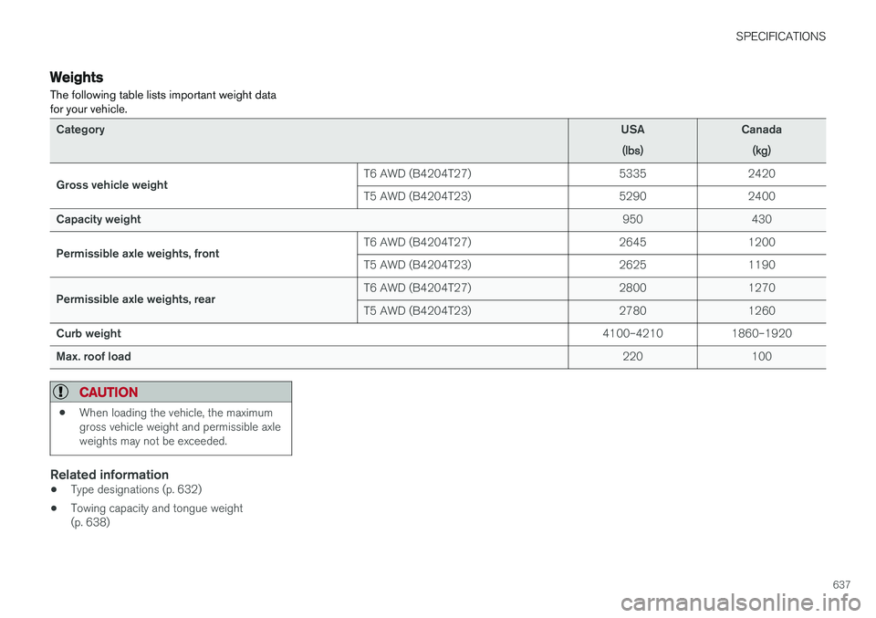
Weights The following table lists important weight data for your vehicle.
CategoryUSA
(lbs)Canada(kg)
Gross vehicle weight T6 AWD (B4204T27) 5335 2420
T5 AWD (B4204T23) 5290 2400
Capacity weight 950 430
Permissible axle weights, front T6 AWD (B4204T27) 2645 1200
T5 AWD (B4204T23) 2625 1190
Permissible axle weights, rear T6 AWD (B4204T27) 2800 1270
T5 AWD (B4204T23) 2780 1260
Curb weight 4100–4210 1860–1920
Max. roof load 220 100
CAUTION
•When loading the vehicle, the maximum gross vehicle weight and permissible axleweights may not be exceeded.
Related information
• Type designations (p. 632)
• Towing capacity and tongue weight (p. 638)
Page 650 of 662

INDEX
648CZIP (Clean Zone Interior Package) 206
D
Data
recording 33 transferring between vehicle and work-
shop 574
Data sharing 510
Daytime running lights 156Decals location of 632
Defrosting 222
Detection of cyclist 333
Dimensions 635
Dipstick, electronic 584
Direction of rotation 526
Disengaging the shiftlock 417
Display lighting 167
Distance Alert 285, 286, 287 limitations 288
DivX ®
486
Door mirrors 173, 175 compass 456
dimming 174
outer 173, 175
power folding 175
resetting 175
Driveline transmission 413
Drive mode 419 changing 421
Driver Alert Control 356 operation 357, 358
Driver Alert Control limitations 358
Driver performance 92, 93
Driver profile 139 edit 141
select 140
Driver support system 266 Driving cooling system 440
with a trailer 445
Driving economy 433
Driving through standing water 435 driving with a trailer towball load 638
towing capacity 638E
ECO climate 422
ECO mode 422
activate with function button 424
Economical driving 422, 433
Electrical outlet 556 use 558
Electrical system 595
Electric parking brake 407
Electronic immobilizer 246
emergency brake lights 163
Emission inspection readiness 572 Engine overheating 440
start 400
Start/Stop 424
turn off 402
Engine braking, automatic 431 Engine compartment coolant 586
engine oil 583
overview 583
Engine drag control 268
Engine oil 583 filling 584
Page 658 of 662

INDEX
656Steering wheel resistance, speed-depend- ent
266
Stone chips and scratches 624, 625
Stop/start function 424
Storage compartments 554 center console 555
glove compartment 559
sun visor 560
Sunroof pinch protection 170
Sun shade panoramic roof 176, 179
pinch protection 170
rear door 173
Sun visor 560 mirror lighting 166
Support battery 598 Symbols indicator symbols 95
Symbols and messages Adaptive Cruise Control 303
center display's status bar 126
Collision warner with auto-brake 340
Symbols and messages for Assistance at
risk of collision 374
system updates 575
T
Tailgate locking/unlocking 237, 250
open/close with foot movement 259
power 255
unlocking from inside 253
Technician certification 37 Temperature adjusting 227, 228, 229
perceived 203
Temporary spare spare tire 543
Temporary tire sealing system execution, checking 547
Inflating tires 551
location 546
overview 546
sealing compound 546
Terms and conditions services 34
users 510
Tire dimensions 528, 538
Tire pressure decal 533 Tire pressure monitoring calibrating 535
Tires 524 direction of rotation 526
glossary of terms 527
inflation pressure table 643
mounting 542
pressure 643
removal 540
rotation 525
specifications 528, 643
storage 524
tire pressure monitoring 533
tire sealing 546
Tread depth 545
tread wear indicator 527
winter tires 545
Tire sealing system 547
Tire tread 527
Tools 538Top tether anchors (child restraint sys- tems) 72
Total airing function 233, 251 Towbar retractable 443
Towing 449
Towing capacity and towball load 638
Towing eyelet 450
TPMS - Tire Pressure Monitoring System 533
Traction control 268
Traffic information 467