ESP VOLVO V90 CROSS COUNTRY 2021 Owner's Manual
[x] Cancel search | Manufacturer: VOLVO, Model Year: 2021, Model line: V90 CROSS COUNTRY, Model: VOLVO V90 CROSS COUNTRY 2021Pages: 683, PDF Size: 14.19 MB
Page 163 of 683
LIGHTING
161
Active high beam
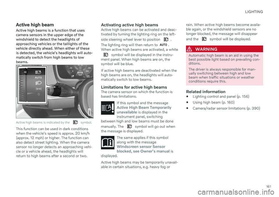
Active high beams is a function that uses camera sensors in the upper edge of thewindshield to detect the headlights ofapproaching vehicles or the taillights of thevehicle directly ahead. When either of theseis detected, the vehicle's headlights will auto-matically switch from high beams to lowbeams.
Active high beams is indicated by the symbol.
This function can be used in dark conditions when the vehicle's speed is approx. 20 km/h(approx. 12 mph) or higher. The function canalso detect street lighting. When the camerasensor no longer detects an approaching vehi-cle or a vehicle ahead, the headlights willreturn to high beams after a second or two.
Activating active high beamsActive high beams can be activated and deac-tivated by turning the lighting ring on the left- side steering wheel lever to position
.
The lighting ring will then return to
.
When active high beams are activated, a white
symbol will be displayed in the instru-
ment panel. When high beams are on, the symbol will be blue. If active high beams are deactivated when the high beams are on, the headlights will auto-matically switch to low beams.
Limitations for active high beamsThe camera sensor on which the function isbased has limitations.
If this symbol and the message
Active High Beam Temporarily
unavailable is displayed in the
instrument panel, switching
between high and low beams must be done manually. The
symbol will go out when
the message is displayed.
The same applies if this symbol along with the message
Windscreen sensor Sensor
blocked, see Owner's manual is
displayed.
Active high beams may be temporarily unavail- able in certain situations, e.g. heavy fog or rain. When active high beams become availa-ble again, or the windshield sensors are nolonger blocked, the message will disappear and the
symbol will be displayed.
WARNING
Automatic high beam is an aid in using the best possible light based on prevailing con-ditions. The driver is always responsible for man- ually switching between high and lowbeam when traffic situations or weatherconditions require this.
Related information
Lighting control and panel (p. 156)
Using high beam (p. 160)
Camera/radar sensor limitations (p. 390)
Page 177 of 683
WINDOWS, GLASS AND MIRRORS
* Option/accessory.175
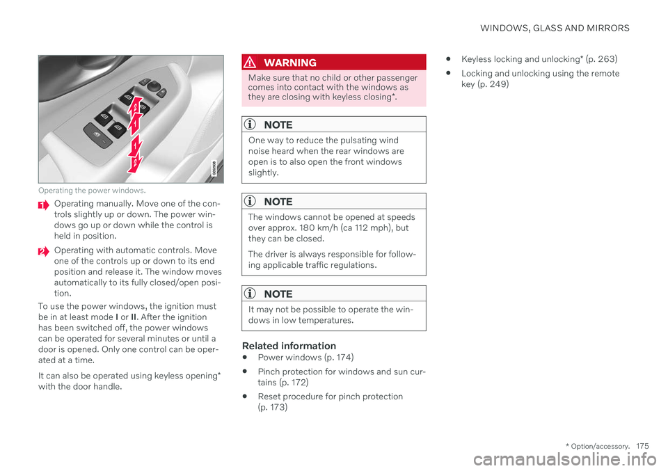
Operating the power windows.
Operating manually. Move one of the con- trols slightly up or down. The power win-dows go up or down while the control isheld in position.
Operating with automatic controls. Move one of the controls up or down to its endposition and release it. The window movesautomatically to its fully closed/open posi-tion.
To use the power windows, the ignition mustbe in at least mode I or II. After the ignition
has been switched off, the power windowscan be operated for several minutes or until adoor is opened. Only one control can be oper-ated at a time. It can also be operated using keyless opening *
with the door handle.
WARNING
Make sure that no child or other passenger comes into contact with the windows as they are closing with keyless closing *.
NOTE
One way to reduce the pulsating wind noise heard when the rear windows areopen is to also open the front windowsslightly.
NOTE
The windows cannot be opened at speeds over approx. 180 km/h (ca 112 mph), butthey can be closed. The driver is always responsible for follow- ing applicable traffic regulations.
NOTE
It may not be possible to operate the win- dows in low temperatures.
Related information
Power windows (p. 174)
Pinch protection for windows and sun cur- tains (p. 172)
Reset procedure for pinch protection(p. 173)
Keyless locking and unlocking
* (p. 263)
Locking and unlocking using the remotekey (p. 249)
Page 248 of 683
KEY, LOCKS AND ALARM
* Option/accessory.
246
Lock confirmation settings
Settings for how the vehicle confirms locking and unlocking can be adjusted in the centerdisplay's Settings menu.
To change the locking response settings: 1. Tap
Settings in the center display's Top
view.
2. Tap
My CarLocking.
3. Tap
Visible Locking Feedback to select
when the vehicle should provide a visible response:
Lock
Unlock
Both
Or turn off the function by marking Off .
4. Select to receive an audible response when locking the vehicle by marking
Audible Locking Feedback.
To change the settings for folding door mir- rors * when locking:
1. Tap
Settings in the center display's Top
view.
2. Tap
My CarMirrors and Convenience.
3. Select
Fold Mirror When Locked to acti-
vate or deactivate the function.
Related information
Lock indication (p. 244)
Remote key
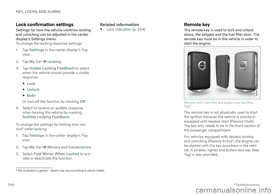
The remote key is used to lock and unlock doors, the tailgate and the fuel filler door. Theremote key must be in the vehicle in order tostart the engine.
Remote key 3
, Care Key and button-less key (Key
Tag) *.
The remote key is not physically used to start the ignition because the vehicle is standard-equipped with keyless start (Passive Start).The key only needs to be in the front section ofthe passenger compartment. For vehicles equipped with keyless locking and unlocking (Passive Entry) *, the engine can
be started with the key anywhere in the vehi- cle. A smaller, lighter and button-less key (Key Tag) is also provided.
3 The illustration is generic - details may vary according to vehicle model.
Page 263 of 683
KEY, LOCKS AND ALARM
* Option/accessory.261
This device complies with part 15 of the FCC Rules. Operation is subject to the followingtwo conditions: (1) This device may not cause harmful interference, and (2) this device must acceptany interference received, includinginterference that may cause undesiredoperation. CAUTION: Changes or modifications not expressly approved by the party responsiblefor compliance could void the user
Page 281 of 683
DRIVER SUPPORT
}}
* Option/accessory.279
WARNING
If the temperature rises too high, the power steering may be forced to switch off com-pletely. In such a situation, the driver dis- play shows the message
Power steering
failure Stop safely along with a symbol.
Changing the level of steering wheel resistance *
In INDIVIDUAL drive mode, the level of steer- ing wheel resistance can be adjusted. 1.
Tap
Settings in the center display's Top
view.
2. Select
My CarDrive ModesSteering Force.
Steering wheel resistance settings can only be accessed if the vehicle is stationary or is mov-ing straight ahead at a low speed.
Related information
Driver support systems (p. 278)
Drive modes
* (p. 419)
Electronic Stability Control
The Electronic Stability Control (ESC 1
) func-
tion helps the driver avoid skidding and improves the vehicle's directional stability.
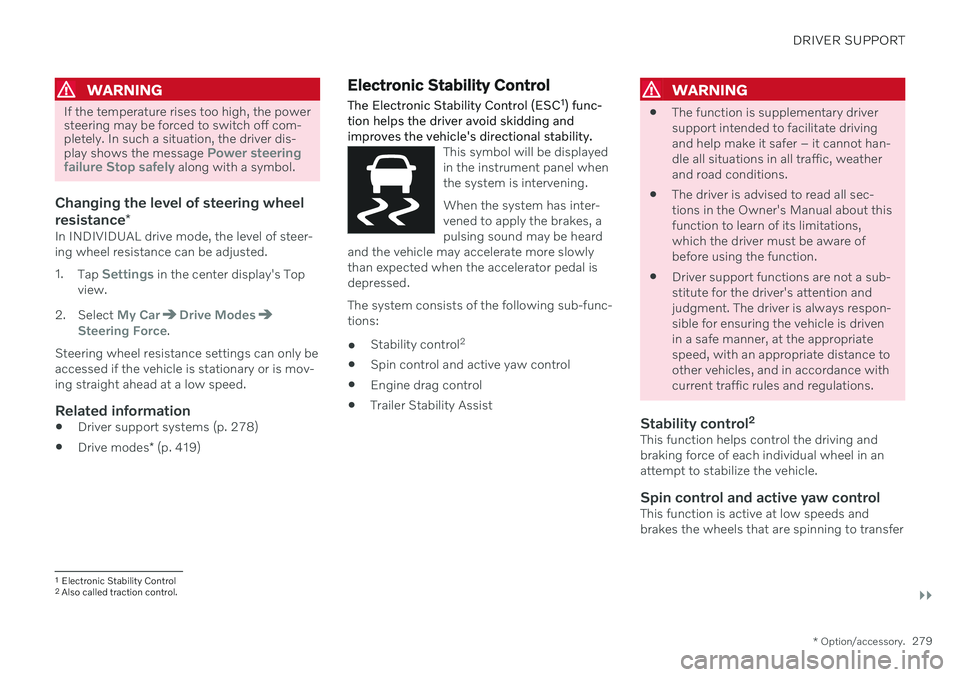
This symbol will be displayed in the instrument panel whenthe system is intervening. When the system has inter- vened to apply the brakes, apulsing sound may be heard
and the vehicle may accelerate more slowlythan expected when the accelerator pedal isdepressed.
The system consists of the following sub-func- tions:
Stability control 2
Spin control and active yaw control
Engine drag control
Trailer Stability Assist
WARNING
The function is supplementary driver support intended to facilitate drivingand help make it safer – it cannot han-dle all situations in all traffic, weatherand road conditions.
The driver is advised to read all sec-tions in the Owner's Manual about thisfunction to learn of its limitations,which the driver must be aware ofbefore using the function.
Driver support functions are not a sub-stitute for the driver's attention andjudgment. The driver is always respon-sible for ensuring the vehicle is drivenin a safe manner, at the appropriatespeed, with an appropriate distance toother vehicles, and in accordance withcurrent traffic rules and regulations.
Stability control 2This function helps control the driving andbraking force of each individual wheel in anattempt to stabilize the vehicle.
Spin control and active yaw controlThis function is active at low speeds andbrakes the wheels that are spinning to transfer
1
Electronic Stability Control
2 Also called traction control.
Page 286 of 683
DRIVER SUPPORT
* Option/accessory.
284
Connected Safety 10
Connected Safety communicates information between your vehicle and other vehicles via the Internet 11
. The function is designed to
notify the driver of any hazardous road condi- tions ahead.
The function can notify the driver if another vehicle further down the road has activated itshazard warning flashers or detected slipperyroad conditions. You will also be notified ifyour own vehicle detects slippery road condi-tions. Connected Safety can assist the driver with the following:
Hazard warning flashers alert
Slippery road alerts
Connected Safety communication betweenvehicles only works for vehicles that are equip-ped with the function and have it activated.
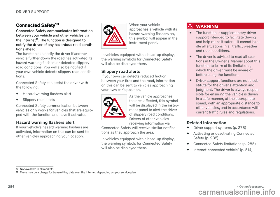
Hazard warning flashers alertIf your vehicle's hazard warning flashers areactivated, information on this can be sent toother vehicles approaching your location. When your vehicleapproaches a vehicle with itshazard warning flashers on,this symbol will appear in theinstrument panel.
In vehicles equipped with a head-up display, the warning symbols for Connected Safetywill also be displayed there.
Slippery road alertsIf your own car detects reduced frictionbetween your tires and the road, informationon this can be sent to vehicles approachingyour own car's position.
As the vehicle approachesthe area affected, this symbolwill be displayed in the instru-ment panel to alert the driverof slippery road conditions.Drivers of other vehiclesreceiving information via
Connected Safety will receive similar notifica-tions as they approach the area.
In vehicles equipped with a head-up display, the warning symbols for Connected Safetywill also be displayed there.
WARNING
The function is supplementary driver support intended to facilitate drivingand help make it safer – it cannot han-dle all situations in all traffic, weatherand road conditions.
The driver is advised to read all sec-tions in the Owner's Manual about thisfunction to learn of its limitations,which the driver must be aware ofbefore using the function.
Driver support functions are not a sub-stitute for the driver's attention andjudgment. The driver is always respon-sible for ensuring the vehicle is drivenin a safe manner, at the appropriatespeed, with an appropriate distance toother vehicles, and in accordance withcurrent traffic rules and regulations.
Related information
Driver support systems (p. 278)
Activating or deactivating ConnectedSafety (p. 285)
Connected Safety limitations (p. 285)
Internet-connected vehicle
* (p. 514)
10
Not available in all markets.
11 There may be a charge for transmitting data over the Internet, depending on your service plan.
Page 288 of 683
||
DRIVER SUPPORT
* Option/accessory.
286 sult a Volvo retailer for more information on covered areas.
WARNING
In certain situations, the function may give false warnings of slippery roadconditions.
The function cannot always detectother vehicles with activated hazardwarning factors or detect all stretchesof road with slippery conditions.
Related information
Connected Safety (p. 284)
Internet-connected vehicle
* (p. 514)
Road Sign Information *
The Road Sign Information (RSI 13
) function
can help the driver observe speed-related road signs.
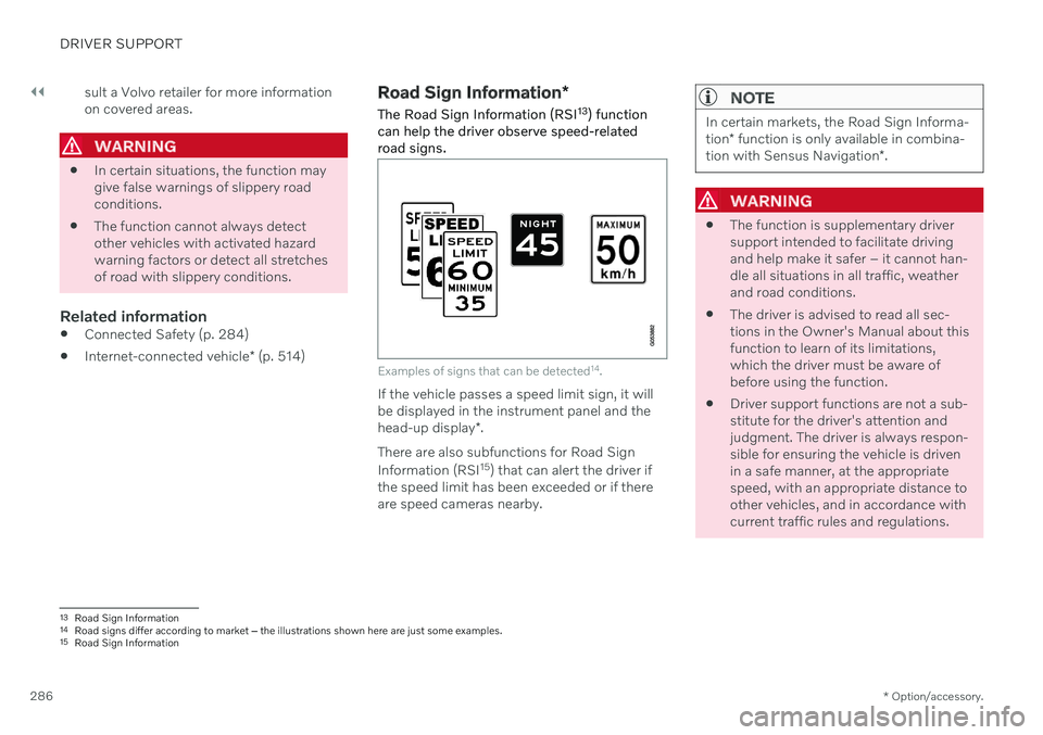
Examples of signs that can be detected 14
.
If the vehicle passes a speed limit sign, it will be displayed in the instrument panel and the head-up display *.
There are also subfunctions for Road Sign Information (RSI 15
) that can alert the driver if
the speed limit has been exceeded or if there are speed cameras nearby.
NOTE
In certain markets, the Road Sign Informa- tion * function is only available in combina-
tion with Sensus Navigation *.
WARNING
The function is supplementary driver support intended to facilitate drivingand help make it safer – it cannot han-dle all situations in all traffic, weatherand road conditions.
The driver is advised to read all sec-tions in the Owner's Manual about thisfunction to learn of its limitations,which the driver must be aware ofbefore using the function.
Driver support functions are not a sub-stitute for the driver's attention andjudgment. The driver is always respon-sible for ensuring the vehicle is drivenin a safe manner, at the appropriatespeed, with an appropriate distance toother vehicles, and in accordance withcurrent traffic rules and regulations.
13
Road Sign Information
14 Road signs differ according to market ‒ the illustrations shown here are just some examples.
15 Road Sign Information
Page 294 of 683
||
DRIVER SUPPORT
* Option/accessory.
292
WARNING
The function is supplementary driver support intended to facilitate drivingand help make it safer – it cannot han-dle all situations in all traffic, weatherand road conditions.
The driver is advised to read all sec-tions in the Owner's Manual about thisfunction to learn of its limitations,which the driver must be aware ofbefore using the function.
Driver support functions are not a sub-stitute for the driver's attention andjudgment. The driver is always respon-sible for ensuring the vehicle is drivenin a safe manner, at the appropriatespeed, with an appropriate distance toother vehicles, and in accordance withcurrent traffic rules and regulations.
Using engine braking instead of applying the brakes
Cruise Control regulates speed by lightly applying the brakes. On downgrades, it cansometimes be desirable to roll a bit faster andlet speed be reduced instead by engine brak-ing alone. The driver can temporarily disen-gage the Cruise Control braking function. To disengage CC:
–Press the accelerator pedal about halfway down and then release it.
> Cruise Control will automatically disen-
gage the automatic brake function and speed will only be reduced using theengine braking function.
Related information
Driver support systems (p. 278)
Selecting and activating cruise control(p. 292)
Deactivating cruise control (p. 293)
Cruise control standby mode (p. 294)
Adjusting set speed for driver support(p. 321)
Switching between cruise control and Adaptive Cruise Control
* in the center dis-
play (p. 301)
Selecting and activating cruise control The Cruise Control (CC 29
) function must be
selected and activated in order to regulate speed.
In order to start Cruise Control from standby mode, the vehicle's current speed must be30 km/h (20 mph) or higher.
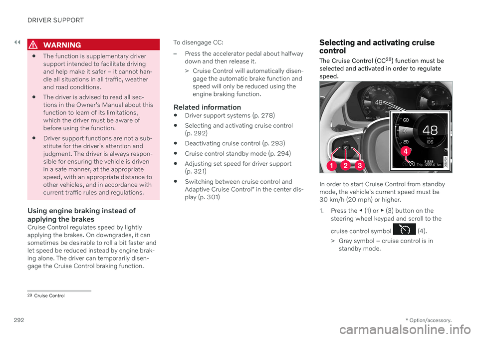
1. Press the ◀ (1) or ▶ (3) button on the
steering wheel keypad and scroll to the cruise control symbol
(4).
> Gray symbol – cruise control is in standby mode.
29Cruise Control
Page 297 of 683
DRIVER SUPPORT
* Option/accessory.295
cle. When there are no longer slower-moving vehicles ahead, the vehicle will return to theset speed. If the Curve Speed Assist (CSA)
* function is
activated, it may also affect the vehicle's speed. Adaptive Cruise Control is designed to: smoothly regulate speed. The driver must apply the brakes in situations requiringimmediate braking. For example, whenthere are great differences in speedbetween vehicles or if the vehicle aheadbrakes suddenly. Due to limitations in theradar sensor, braking may occur unexpect-edly or not at all.
follow a vehicle ahead in the same laneand maintain a time interval to that vehicleset by the driver. If the radar sensor doesnot detect a vehicle ahead, it will insteadmaintain the speed set by the driver. Thiswill also happen if the speed of the vehicleahead exceeds the set speed for your vehi-cle.
WARNING
The function is supplementary driver support intended to facilitate drivingand help make it safer – it cannot han-dle all situations in all traffic, weatherand road conditions.
The driver is advised to read all sec-tions in the Owner's Manual about thisfunction to learn of its limitations,which the driver must be aware ofbefore using the function.
Driver support functions are not a sub-stitute for the driver's attention andjudgment. The driver is always respon-sible for ensuring the vehicle is drivenin a safe manner, at the appropriatespeed, with an appropriate distance toother vehicles, and in accordance withcurrent traffic rules and regulations.
CAUTION
Only a workshop may perform mainte- nance on driver support components – anauthorized Volvo workshop is recom-mended.
Related information
Driver support systems (p. 278)
Adaptive Cruise Control
* controls (p. 296)
Adaptive Cruise Control
* displays (p. 296)
Selecting and activating Adaptive Cruise Control
* (p. 297)
Adaptive Cruise Control
* limitations
(p. 300)
Symbols and messages for AdaptiveCruise Control
* (p. 302)
Collision risk warning from driver support (p. 319)
Setting time interval to the vehicle ahead(p. 322)
Adjusting set speed for driver support(p. 321)
Auto-hold braking with driver support(p. 323)
Switching target vehicles with driver sup-port (p. 320)
Passing assistance
* (p. 318)
Contacting Volvo (p. 26)
Page 299 of 683
DRIVER SUPPORT
}}
* Option/accessory.297
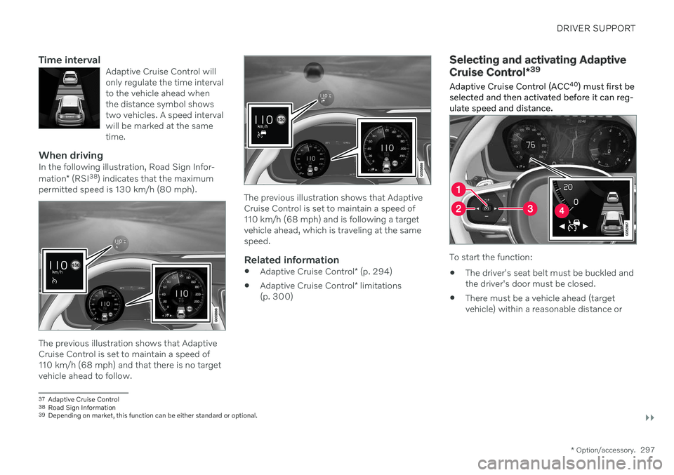
Time intervalAdaptive Cruise Control will only regulate the time intervalto the vehicle ahead whenthe distance symbol showstwo vehicles. A speed intervalwill be marked at the sametime.
When drivingIn the following illustration, Road Sign Infor- mation* (RSI 38
) indicates that the maximum
permitted speed is 130 km/h (80 mph).
The previous illustration shows that Adaptive Cruise Control is set to maintain a speed of110 km/h (68 mph) and that there is no targetvehicle ahead to follow.
The previous illustration shows that Adaptive Cruise Control is set to maintain a speed of110 km/h (68 mph) and is following a targetvehicle ahead, which is traveling at the samespeed.
Related information
Adaptive Cruise Control
* (p. 294)
Adaptive Cruise Control
* limitations
(p. 300)
Selecting and activating Adaptive Cruise Control *39
Adaptive Cruise Control (ACC 40
) must first be
selected and then activated before it can reg- ulate speed and distance.
To start the function:
The driver's seat belt must be buckled and the driver's door must be closed.
There must be a vehicle ahead (targetvehicle) within a reasonable distance or
37
Adaptive Cruise Control
38 Road Sign Information
39 Depending on market, this function can be either standard or optional.