stop start VOLVO V90 CROSS COUNTRY 2021 Service Manual
[x] Cancel search | Manufacturer: VOLVO, Model Year: 2021, Model line: V90 CROSS COUNTRY, Model: VOLVO V90 CROSS COUNTRY 2021Pages: 683, PDF Size: 14.19 MB
Page 459 of 683

STARTING AND DRIVING
* Option/accessory.457
WARNING
If you use HomeLink ®
to open a garage
door or gate, be sure no one is near the gate or door while it is in motion.
Do not use HomeLink ®
with any
garage door opener that lacks safetystop and reverse features as requiredby U.S. federal safety standards (thisincludes any garage door opener modelmanufactured before April 1, 1982). Agarage door that cannot detect anobject - signaling the door to stop andreverse - does not meet current U.S.federal safety standards. For moreinformation, contact HomeLink at:homelink.com.
Related information
HomeLink ®
* (p. 454)
Programming HomeLink ®
* (p. 455)
Type approval for HomeLink ®
* (p. 457)
Type approval for HomeLink ®
*30
FCC (USA) and IC (Canada)This device complies with FCC rules part 15 and Industry Canada RSS-210. Operation issubject to the following two conditions: (1)This device may not cause harmful interfer-ence, and (2) This device must accept anyinterference that may be received includinginterference that may cause undesired opera-tion.
WARNING
The transmitter has been tested and com- plies with FCC and IC rules. Changes ormodifications not expressly approved bythe party responsible for compliance couldvoid the user's authority to operate the device.
31
Type approval for EUGentex Corporation hereby declares that HomeLink
®
Model UAHL5 complies with the
Radio equipment directive 2014/53/EU. Wavelengths within which the radio equip- ment operates:
433.05MHz-434.79MHz <10mW E.R.P.
868.00MHz-868.60MHz <25mW E.R.P.
868.70MHz-868.20MHz <25mW E.R.P.
869.40MHz-869.65MHz <25mW E.R.P.
869.70MHz-870.00MHz <25mW E.R.P.
Certificate holder address: Gentex Corpora-tion, 600 North Centennial Street, Zeeland MI49464, USA For further details, search for support informa- tion on type approval at volvocars.com
Related information
HomeLink ®
* (p. 454)
29
Certain markets only.
30 Certain markets only.
31 The term "IC:" before the certification/registration number only signifies that Industry Canada technical specifications were met.
Page 460 of 683

STARTING AND DRIVING
* Option/accessory.
458
Compass *
An integrated compass 32
in the upper right
corner of the rearview mirror shows the direction the vehicle is traveling.
Rearview mirror with compass.
Eight different compass directions are shown with the abbreviations: N (north), NE (north-
east), E (east), SE (southeast), S (south), SW(southwest), W (west) and NW (northwest).
Related information
Activating and deactivating the compass
*
(p. 458)
Calibrating the compass
* (p. 458)
Activating and deactivating the compass *
An integrated compass 33
in the upper right
corner of the rearview mirror shows the direction the vehicle is traveling.
The compass is automatically activated when the vehicle is started. To deactivate/activate the compass manually:
–Use a paper clip or similar object to press the button on the bottom of the mirror.
> If the compass is deactivated when the vehicle is switched off, it will not be activated the next time the vehicle isstarted. The compass will then need tobe activated manually.
Related information
Compass
* (p. 458)
Calibrating the compass
* (p. 458)
Calibrating the compass *
The globe is divided into 15 magnetic zones. The compass 34
should be calibrated if the
vehicle is driven from one zone to another.
1. Stop the vehicle in a large, open area away from steel constructions and high-voltage power lines.
2. Start the engine and switch off all electri- cal equipment (climate system, wipers,etc.) and make sure all doors are closed.
NOTE
Calibration may fail or not even be initiated if electrical equipment is not turned off.
3. Hold the button on the bottom of the rear-view mirror pressed for about 3 seconds (using e.g. a paper clip). The number of thecurrent magnetic zone is shown.
32Rearview mirror with compass is available as an option only on certain markets and models.
33 Rearview mirror with compass is available as an option only on certain markets and models.
34 Rearview mirror with compass is available as an option only on certain markets and models.
Page 546 of 683
||
WHEELS AND TIRES
544
General information about the tire pressure monitoring system
In the following description, the tire monitor- ing system is generally referred to as TPMS. Each tire, including the spare (if provided)7
should be checked monthly when cold and inflated to the inflation pressure recom-mended by the vehicle manufacturer on thevehicle placard or tire inflation pressure label.(If your vehicle has tires of a different size thanthe size indicated on the vehicle placard or tireinflation pressure label, you should determinethe proper tire inflation pressure for thosetires.) As an added safety feature, your vehicle has been equipped with a tire pressure monitoringsystem (TPMS) that illuminates a low tirepressure telltale when one or more of yourtires is significantly under-inflated. Accord-ingly, when the low tire pressure telltale illumi-nates, you should stop and check your tires assoon as possible, and inflate them to theproper pressure. Driving on a significantly under-inflated tire causes the tire to overheat and can lead to tirefailure. Under-inflation also reduces fuel effi-ciency and tire tread life, and may affect thevehicle's handling and stopping ability. Please note that the TPMS is not a substitute forproper tire maintenance, and it is the driver'sresponsibility to maintain correct tire pressure,even if under-inflation has not reached thelevel to trigger illumination of the TPMS lowtire pressure telltale. Your vehicle has also been equipped with a TPMS malfunction indicator to indicate whenthe system is not operating properly. TheTPMS malfunction indicator is combined withthe low tire pressure telltale. When the systemdetects a malfunction, the telltale will flash forapproximately one minute and then remaincontinuously illuminated. This sequence willcontinue upon subsequent vehicle start-ups aslong as the malfunction exists. When the mal-function indicator is illuminated, the systemmay not be able to detect or signal low tirepressure as intended. TPMS malfunctions may occur for a variety of reasons, including the installation of replace-ment or alternate tires or wheels on the vehi-cle that prevent the TPMS from functioningproperly. Always check the TPMS malfunction telltale after replacing one or more tires or wheels onyour vehicle to ensure that the replacement oralternate tires and wheels allow the TPMS tocontinue to function properly.
To keep in mind
Always save the new inflation pressure inthe system after changing a tire or adjust-ing the inflation pressure.
If you switch to a tire of another size thanthe factory-mounted tires, the systemmust be reset by storing a new inflationpressure for these tires to avoid falsewarnings.
If a spare wheel 8
is used, it is possible that
the tire pressure monitoring system willnot work correctly due to the differencesbetween the wheels.
The system does not replace the need forregular tire inspection and maintenance.
It is not possible to deactivate the tirepressure monitoring system.
WARNING
Incorrect inflation pressure could lead to tire failure, which could cause thedriver to lose control of the vehicle.
The system cannot predict sudden tiredamage.
6
Tire Pressure Monitoring System (TPMS)
7 Not available on all models.
8 Not available on all models.
Page 569 of 683
LOADING, STORAGE AND PASSENGER COMPARTMENT
567
Using the electrical outlets
The 12 V outlet can be used for devices intended for this such as MP3 players, cool-ers and cellular phones.
The ignition must be in at least mode I for the
outlets to supply current. The outlets will then be active as long as there is sufficient chargein the start battery. If the engine is turned off and the vehicle is locked, the outlets will be deactivated. If theengine is turned off and the vehicle remainsunlocked, the sockets will remain active for upto 7 minutes.
NOTE
Bear in mind that using the electrical out- lets when the engine is off could cause thestarter battery to have too low of a chargelevel, which could limit other functionality. Accessories connected to the electrical outlets can be activated even when thevehicle electrical system is off or if precon-ditioning is used. For this reason, discon-nect plugs when they are not in use to pre-vent the starter battery from becoming dis-charged.
WARNING
Do not use accessories with large or heavy plugs – they could damage theoutlet or come loose while you are driv-ing.
Do not use accessories that couldcause disruptions to e.g. the vehicle'sradio receiver or electrical system.
Position the accessory so that there isno risk of it injuring the driver or pas-sengers in the event of heavy brakingor a collision.
Pay attention to connected accessoriesas they can generate heat that couldburn passengers or the interior.
Using 12 V outlets1. Remove the stopper (tunnel console) or
fold down the cover (trunk/cargo com-partment) over the socket and plug in thedevice.
2. Unplug the device and put the stopper back in (tunnel console) or fold up thecover (trunk/cargo compartment) whenthe socket is not in use or left unattended.
CAUTION
The maximum power is 120 W (10 A) per outlet.
Related information
Electrical outlets (p. 566)
Passenger compartment interior (p. 564)
Page 598 of 683
||
MAINTENANCE AND SERVICE
596and display messages are used to alert the driver. Some engine variants have both sys-tems. Contact a Volvo retailer for more infor-mation. Change the engine oil and oil filter according to the schedule specified in the Warranty andMaintenance Records Information booklet.Oils of a higher grade than that specified maybe used. If the vehicle is driven in adverse con-ditions, Volvo recommends using an oil with ahigher grade than that specified.
Related information
Checking and filling engine oil (p. 596)
Engine oil specifications (p. 658)
Volvo Cars support site (p. 21)
Checking and filling engine oil
The engine oil level is monitored by an elec- tronic oil level sensor.
Viewing oil level in the center display
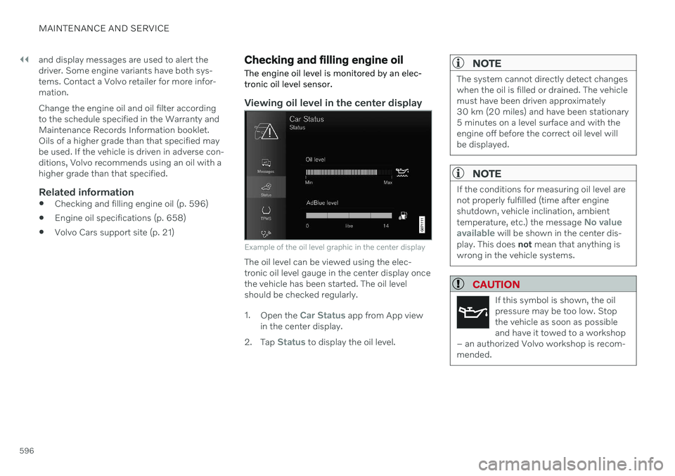
Example of the oil level graphic in the center display
The oil level can be viewed using the elec- tronic oil level gauge in the center display oncethe vehicle has been started. The oil levelshould be checked regularly. 1. Open the
Car Status app from App view
in the center display.
2. Tap
Status to display the oil level.
NOTE
The system cannot directly detect changes when the oil is filled or drained. The vehiclemust have been driven approximately30 km (20 miles) and have been stationary5 minutes on a level surface and with theengine off before the correct oil level willbe displayed.
NOTE
If the conditions for measuring oil level are not properly fulfilled (time after engineshutdown, vehicle inclination, ambient temperature, etc.) the message
No value
available will be shown in the center dis-
play. This does not mean that anything is
wrong in the vehicle systems.
CAUTION
If this symbol is shown, the oil pressure may be too low. Stopthe vehicle as soon as possibleand have it towed to a workshop
– an authorized Volvo workshop is recom-mended.
Page 602 of 683
MAINTENANCE AND SERVICE
600
Starter battery The starter battery is used to start the electri- cal system and power the starter motor andother electrical equipment in the vehicle.
The vehicle has a single-pole electrical system that uses the chassis and engine mount asconductors. The vehicle has a voltage-regulated alternating current generator. The starter battery is a 12 V battery, dimen- sioned for the carbon dioxide-reducing func-tions Start/Stop and regenerative chargingand to support the function of the vehicle'svarious systems. The service life and performance of the starter battery are affected by factors such as drivingstyle, driving conditions, climate, battery dis-charges, number of starts, etc. Never disconnect the starter battery while the engine is running.
Make sure the cables to the starter batteryare correctly connected and the clampsare securely tightened.
WARNING
Batteries generate hydrogen gas, which is flammable and explosive.
Do not connect the jumper cable toany part of the fuel system or to anymoving parts. Avoid touching hotmanifolds.
Battery fluid contains sulfuric acid. Donot allow battery fluid to contact eyes,skin, fabrics or painted surfaces.
If contact occurs, flush the affectedarea immediately with water. Obtainmedical help immediately if eyes areaffected.
Never expose the battery to open flameor electric spark. Do not smoke nearthe battery. Failure to follow theinstructions for jump starting can leadto injury.
Starter battery service life and capacity
The service life of the starter battery is affec- ted by several factors, such as number ofstarts, battery discharges, driving style, drivingconditions, climate, etc. The starting capacityof the battery reduces gradually over time. Thebattery must therefore be recharged if thevehicle is not used for a long period of time orif it is only driven short distances. Severe cold further limits starting capacity. If the starterbattery becomes discharged too many times,its service life will be shortened. To help keep the starter battery in good condi- tion, the vehicle should be driven at least15 minutes per week or the battery should beconnected to a battery charger with automatictrickle charging. A starter battery that isalways kept fully charged has the maximumservice life.
Location
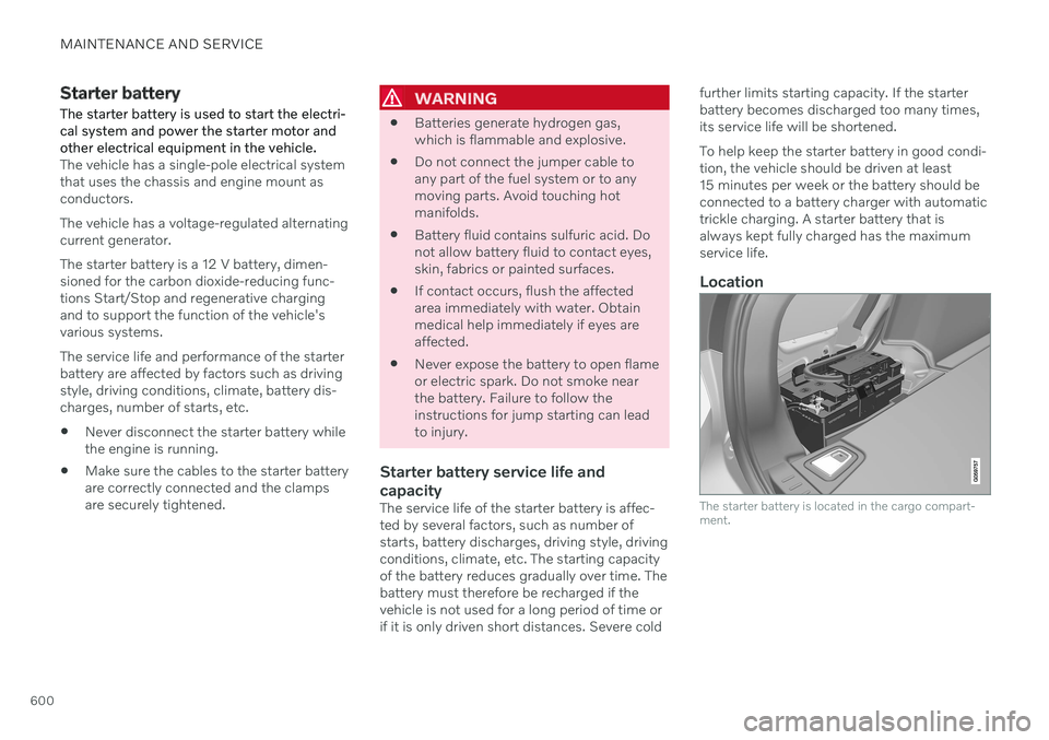
The starter battery is located in the cargo compart- ment.
Page 604 of 683

MAINTENANCE AND SERVICE
602
Support battery Vehicles with the Start/Stop function are equipped with two batteries – a more power-ful 12 V start battery and a support batterythat provides stronger current during thefunction's start sequence.
The 12 V support battery is located in a box next to the spring strut in the engine compartment.
If the vehicle is instead equipped with a 48 V support battery, it is located under the cargo compartment.The box over the 48 V support battery may only beremoved by an authorized workshop.
WARNING
High voltage may be dangerous if handled incorrectly. Do not touch anything on bat-teries that is not clearly described in thisOwner's Manual. Never use a 48 V support battery to jump start the vehicle.
External electrical equipment may notunder any circumstance be connectedto the 48 V battery.
Only a workshop may replace or per-form service on the 48 V battery – anauthorized Volvo workshop is recom-mended.
NOTE
The higher the current consumption in the vehicle, the more the alternator hasto work and the batteries have to becharged = increased fuel consumption.
When the starter battery capacity hasdropped below the lowest permissiblelevel, the Start/Stop function is disen-gaged.
When the Start/Stop function is temporarily reduced due to high current consumption: The engine will auto-start, even if the driver does not lift their foot from thebrake pedal.
The support battery does not normally requiremore service than the start battery. If you haveany questions or concerns, consult a work-shop ‒
an authorized Volvo workshop is rec-
ommended.
Page 605 of 683

MAINTENANCE AND SERVICE
603
CAUTION
If the following is not observed, the Start/ Stop function may temporarily stop work-ing after connection of an external starterbattery or battery charger: The negative battery terminal of thevehicle's starter battery must
never be
used to connect an external starterbattery or battery charger – only thevehicle's negative charging pointshould be used as a grounding point.
NOTE
If the starter battery has been discharged to the extent that the vehicle does not havenormal electrical functions and the enginemust then be jump-started with an externalbattery or a battery charger, the Start/Stopfunction may remain activated. If the Start/Stop function shortly thereafter auto-stopsthe engine, there is a huge risk that auto-start of the engine will fail due to insuffi-cient battery capacity since the battery hadnot had time to recharge. If the vehicle has been jump-started or if there has not been enough time for thebattery to be charged with a batterycharger, the Start/Stop function should betemporarily deactivated until the batteryhas been recharged by the vehicle. At anambient temperature of about +15°C(about 60°F), the battery must be chargedby the vehicle for at least one hour. Atlower ambient temperatures, the chargingtime can increase to 3-4 hours. It is advisa-ble to charge the battery with an externalbattery charger.
Specifications for support battery
Type AGM
Voltage (V) 12
Cold start capacity A
-
CCA B
(A) 170
Dimensions, L×W×H 150×90×130 mm
(5.9×3.5×5.1 inches)
Capacity (Ah) 10
A According to EN standard.
B Cold Cranking Amperes.
CAUTION
If replacing the battery, make sure you replace it with a battery of the same size,cold start capacity and type as the originalbattery (see the decal on the battery).
Related information
Starter battery (p. 600)
Start/Stop function (p. 425)
Battery symbols (p. 604)
Battery recycling (p. 604)
Page 666 of 683
INDEX
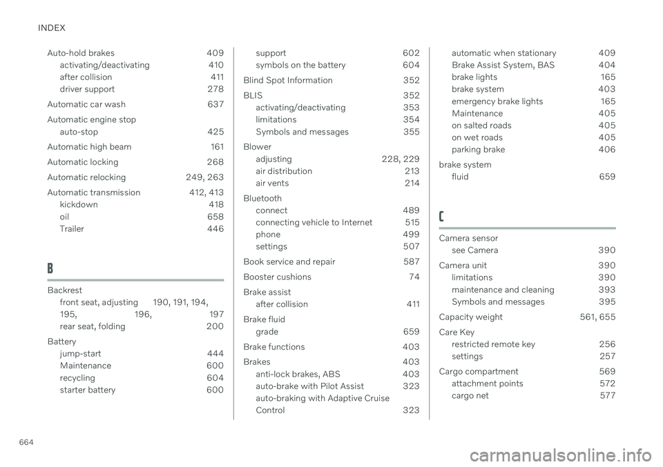
664Auto-hold brakes 409
activating/deactivating 410
after collision 411
driver support 278
Automatic car wash 637 Automatic engine stop auto-stop 425
Automatic high beam 161
Automatic locking 268
Automatic relocking 249, 263
Automatic transmission 412, 413 kickdown 418
oil 658
Trailer 446
B
Backrestfront seat, adjusting 190, 191, 194, 195 , 196, 197
rear seat, folding 200
Battery jump-start 444
Maintenance 600
recycling 604
starter battery 600
support 602
symbols on the battery 604
Blind Spot Information 352
BLIS 352 activating/deactivating 353
limitations 354
Symbols and messages 355
Blower adjusting 228, 229
air distribution 213
air vents 214
Bluetooth connect 489
connecting vehicle to Internet 515
phone 499
settings 507
Book service and repair 587
Booster cushions 74 Brake assist after collision 411
Brake fluid grade 659
Brake functions 403
Brakes 403 anti-lock brakes, ABS 403
auto-brake with Pilot Assist 323auto-braking with Adaptive Cruise
Control 323automatic when stationary 409
Brake Assist System, BAS 404
brake lights 165
brake system 403
emergency brake lights 165
Maintenance 405
on salted roads 405
on wet roads 405
parking brake 406
brake system fluid 659
C
Camera sensorsee Camera 390
Camera unit 390 limitations 390
maintenance and cleaning 393
Symbols and messages 395
Capacity weight 561, 655 Care Key restricted remote key 256
settings 257
Cargo compartment 569 attachment points 572
cargo net 577
Page 669 of 683
INDEX
667
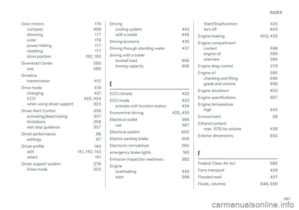
Door mirrors 176
compass 458
dimming 177
outer 176
power folding 177
resetting 177
store position 192, 193
Download Center 585 use 585
Driveline transmission 412
Drive mode 419 changing 421
ECO 422, 424
when using driver support 323
Driver Alert Control 356 activating/deactivating 357
limitations 358
rest stop guidance 357
Driver performance 96 settings 97
Driver profile 140 edit 141, 142, 143
select 141
Driver support system 278 Drive mode 323
Drivingcooling system 442
with a trailer 446
Driving economy 435
Driving through standing water 437driving with a trailer towball load 656
towing capacity 656
E
ECO climate 422
ECO mode 422
activate with function button 424
Economical driving 422, 435
Electrical outlet 566 use 567
Electrical system 600
Electric parking brake 406
Electronic immobilizer 260
emergency brake lights 165
Emission inspection readiness 582 Engine overheating 442
start 398
Start/Stopfunction 425
turn off 400
Engine braking 403, 433 Engine compartment coolant 598
engine oil 595
overview 594
Engine drag control 279
Engine oil 595 checking and filling 596
grade and volume 658
Engine shutdown 400
Engine specifications 657Engine temperature high 442
Environment 28Ethanol content max. 10% by volume 439
Exterior dimensions 653
F
Federal Clean Air Act 582
Ferry transport 429
Flooded road 437
Fluids, volumes 646, 659